1. * GB780087 (A)
Description: GB780087 (A) ? 1957-07-31
Improvements relating to lifting jacks
Description of GB780087 (A)
PATENT SPECIFICATION
Inventor: AUSTIN COLLINS :! ' Date of filing Complete Specification:
Jan. 2, 1956.
Application Date: Jan. 6, 1955. No. 371/55.
Complete Specification Published: July 31, 1957.
Index at acceptance:-Class 78(3), C(4: 8).
International Classification:-B66f.
COMPLETE SPECIFICATION
Improvements relating to Lifting Jacks We, PRIMA INDUSTRIES LIMITED,
of London House, Dibdale Street, Dudly, in the County of Worcester, a
Company incorporated under the Laws of the Kingdom of Great Britain,
do hereby declare the invention for which we pray that a patent may be
granted to us and the method by which it is to be performed, to be
particularly described in and by the following statement:-
This invention has reference to improvements relating to lifting jacks
and is concerned particularly with lifting jacks for motor vehicles of
the kind known in the industry as tubular single point lifting jacks
and which incorporate an inner tubular element, an outer tubular
element displaceable therein and a hooked lifting element which is
carried by and which is displaceable with the said outer tubular
element.
It is the customary practice with lifting jacks of the kind aforesaid
to weld the hooked lifting member to the slidable outer tube but it is
found that the appearance of the lifting jacks manufactured in
accordance with the said practice is marred by the welding operation
whilst the general manner of construction is such that fracture of the
hooked lifting members has been known to have occurred in use.
The present invention has for its object to provide an improved
lifting jack of the kind referred to which whilst retaining the
simplicity and relative cheapness of jacks of the said kind as
2. manufactured heretofore is less liable to fracture of the hook lifting
element in use and is more pleasing in appearance.
The invention consists of an improved lifting jack of the kind
hereinbefore referred to which is characterised in that the
displaceable tubular element is formed with a recess in the outer
periphery thereof and in that the hooked lifting element incorporates
a clamping means which is adapted to be seated within the said recess.
The invention also resides in a lifting jack constructed, arranged and
adapted for use substantially as will be described hereinafter.
An embodiment of the invention will now be described in its
application to a single point 780087 lifting jack for motor vehicles
which as to its general construction follows known practice.
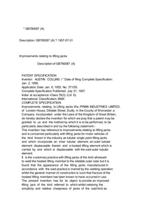
In the drawings:- 50 Figure 1 is a view of the improved single point
lifting jack shown partly in elevation but mainly in vertical section,
and Figure 2 is a cross section partly broken away for the sake of
clearness taken on the 55 plane indicated by the line 2-2 in Figure 1
looking in the direction of the arrows to the said line.
The single point lifting jack for motor vehicles which as to its
general construction as has 60 beenstated hereinbefore follows known
practice incorporates an inner tubular section 10 which has a foot 101
welded to the bottom end thereof and a nut 11 which is secured within
the upper end by turning the upper end 102 of the tube 65 into a
groove 111 formed in the outer periphery of the nut 11, and a
telescopic outer tubular section 12 which has rotatably mounted in
ball bearings secured within the upper end thereof a screw 13 which is
adapted to be 70 rotated by an externally disposed hexagonal head 131
and which is adapted to co-operate with the nut 11 aforesaid.
According to the present embodiment of the invention the telescopic
outer tubular section 75 12 is recessed externally to provide a
shallow annular recess 121 whilst the hooked lifting element 14 which
is required to be secured to the said telescopic outer section 12 is
formed as a malleable casting incorporating a hook 80 section 141 and
an integral split tubular clamping lug section 142 which is adapted to
be threaded over the outer tubular section 12 and which is of
substantially the same depth as the shallow annular recess 121
aforesaid, said 85 split clamping lug section 142 being associated
with ear pieces 143 one of which is provided with a hole 144 through
which may be passed freely the shank of a clamping bolt 15 whilst the
other ear piece is provided with a registering 90 hole 145 which is
tapped for engaging by the shank of the said clamping bolt 15.
Conveniently the split ear piece section of the clamping lug is
produced by first forming the said ear piece section as an undivided
part of the lug section and then "splitting" the ear piece section
along a line of cut by means of a saw.
3. The usual loose annular anti-locking distance piece 17 is allowed to
rest on top of the nut 11 whilst the motion of the outer tubular
section is guided by a split anti-friction bearing sleeve 18 which is
housed within a shallow recess in the upper portion of the outer
periphery of the inner tubular section 10.
For purposes of initial assembly after the outer and inner tubular
sections 10 and 12 respectively have been manufactured and assembled
in the customary manner the clamping bolt 15 is slackened and the
tubular portion of the split lug section 142 threaded over the outer
tubular section 12 until it is in register with the groove 111
whereupon the tubular portion snaps into engagement with the recess
121 under the influence of its own inherent resilience. The clamping
bolt 15 is then tightened to cause the split lug to be compressed on
to and to bind on the bottom surface of the recess 121.
When the split lug is firmly secured on the outer section 12 the
projecting end of the bolt is peened over as is clearly seen at 151 in
Figure 2.
By reason of the formation of the hooked lifting element 14 as a
malleable casting and the secure fixing afforded by compressing the
split lug section into the recess 121 a robust and strong construction
is provided which enables a jack to deal safely with relatively
greater loads than can be dealt with by lifting jacks ofthe kind
heretofore in use.
In addition the appearance of the jack is enhanced.
Although in the embodiment of the invention described the lifting
element 14 is provided with a split lug section the said hooked
lifting element 14 may if desired be made integral with one section of
a two part tubular clamp the complementary section of which is adapted
to be bolted thereto at two opposite points so that when fitted to the
outer tubular section 12 the tubular portions of both parts of the
clamp are secured within the annular recess 121 in the manner of the
tubular section of the split clamping lug first described.
* Sitemap
* Accessibility
* Legal notice
* Terms of use
* Last updated: 08.04.2015
* Worldwide Database
* 5.8.23.4; 93p