The Yagi U-PA antenna is a small but surprisingly efficient UHF antenna for receiving terrestrial television signals. Though much smaller than a full-sized multi-element yagi antenna, tests showed the Yagi U-PA performed very well, with a gain only 3.5-6.5 dB lower than the larger antenna. It has a wide beam width allowing reception of multiple nearby transmitters without repositioning. While it cannot match the specifications of larger antennas, the Yagi U-PA provides solid reception for local television within 20-30 km and is suitable for both indoor and outdoor use with its compact size and discreet design.
Presentation by Steven Soenens, VP Products & Markets
DVB-S2X: history, important performance changes, profiles fit for different applications, efficiency gains, DVB-S2X in action, partners, availability, DVB-S2X Newtec products
International Journal of Engineering Research and Applications (IJERA) is an open access online peer reviewed international journal that publishes research and review articles in the fields of Computer Science, Neural Networks, Electrical Engineering, Software Engineering, Information Technology, Mechanical Engineering, Chemical Engineering, Plastic Engineering, Food Technology, Textile Engineering, Nano Technology & science, Power Electronics, Electronics & Communication Engineering, Computational mathematics, Image processing, Civil Engineering, Structural Engineering, Environmental Engineering, VLSI Testing & Low Power VLSI Design etc.
DTH is a new technology and it has matured to its full potential in other parts of the world. There are many application has been found every day for exploitation of benefits of DTH?
The word ‘DTH’ is synonymous with transmission of digital video channel to home
subscriber’s using a small dish antenna. The DTH utilizes a technology which enables a home to receive high speed internet broadband access data communication, voice over internet protocol (IP) telephony and much more using an open standard Digital Video Broadcasting (DVB) technology. The video channels are received with a suitable set top box. It is Capable of demodulating Motion Picture Engineering Group (MPEG-2) standard videos. It is for the return channel required for other services such as voice over internet protocol and broadband access data communications, that a return channel is also required for the home terminal. The return channel via the satellite is called RCS and is an open standard. Hardware compatible with DVB-RCS technology are readily available in the market in both Ku-band and C-band. DVB-RCS is an international open standard for multimedia satellite network where the return data rates in access of 2 Mbps are possible using low cost user terminals. The forward ink is usually at 40 Mbps.
Today, most satellite TV customers in developed television markets get their programming through a direct broadcast satellite (DBS) provider, such as DISH TV or DTH platform. The provider selects programs and broadcasts them to subscribers as a set package. Basically, the provider’s goal is to bring dozens or even hundreds of channels to the customer’s television in a form that approximates the competition from Cable TV. Unlike earlier programming, the provider’s broadcast is completely digital, which means it has high picture and stereo sound quality.
Early satellite television was broadcast in C-band - radio in the 3.4- gigahertz (GHz) to 7-GHz
frequency range. Digital broadcast satellite transmits programming in the Ku frequency range (10 GHz to 14 GHz). There are five major components involved in a direct to home (DTH) satellite.
This is a technical training presentation on the renewed satcom Newtec DVB-S2 Calculator v2.17 and covers:
- DVB-S
- DVB-S2
- S2 Extensions
For all current Azimuth, Elevation and MDM series (both demods and modems) and includes Sat3Play terminals.
Officially launched beginning of June 2013, this DVB-S2 calculator replaces its widely spread predecessor (which had over 7,000 downloads).
To download the calculator: http://www.newtec.eu/services-training/dvb-s2-calculator
HD Radio Overview
– HD Radio today
– IBOC Signal review
IBOC Broadcast Equipment
Evolution
– 3rd gen architecture
HD PowerBoost Gen4
– HD PowerBoost vs PAR2
HD Multiplex
– Economic Benefits
– Application Areas
The Yagi Antenna design is one of the most brilliant antenna designs. How to make a 433MHz Yagi antenna design for a long-range? Is it easy to DIY a Yagi antenna?
DIY Yagi antenna design program
Yagi antenna design is mainly based on the gain requirements after selecting the number of antenna elements, determining the length of each element, and the distance between the elements and other parameters.
Here are the 7 steps of the Yagi antenna design program.
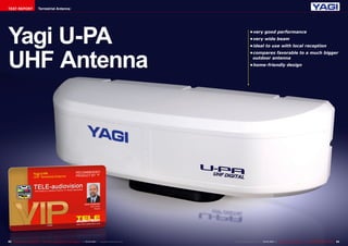
1. TEST REPORT Terrestrial Antenna
Yagi U-PA
UHF Antenna
• very good performance
• very wide beam
• ideal to use with local reception
• compares favorable to a much bigger
outdoor antenna
• home-friendly design
82 TELE-audiovision International — The World‘s Largest Digital TV Trade Magazine — 03-04/2014 — www.TELE-audiovision.com www.TELE-audiovision.com — 03-04/2014 — TELE-audiovision International — 全球发行量最大的数字电视杂志83
2. Small But Surprisingly Efficient
03-04/2014
www.TELE-audiovision.com/14/03/yagi
TEST REPORT Terrestrial Antenna
Terrestrial TV does not
offer as wide a channel
choice as satellite TV, but
it has other strong points,
namely in most countries
among the terrestrial chan-nels
you can find the local tv
channels providing informa-tion
on what is going on in
your neighborhood. Another
strong point is that setting
up a terrestrial antenna can
be a simple and easy-to-do
task.
“Can be” does not mean
“always is”. If you want to
install a multi-element yagi
antenna with complex reflec-tors
your antenna setup will
become a rather complex
one. That’s why many people
prefer simpler solutions and
small compact TV antennas
are becoming more popu-lar.
Generally, they cannot
offer as good performance
as a full size multi-element
yagis but if you live not very
far from the TV transmitters
they can ensure a quite solid
reception while being very
simple in installation. And, if
nicely designed, they can be
more esthetic than yagis.
The Yagi U-PA fits all of the
above. Its size is quite small:
35 x 13.5 x 12.5 cm and it
is very light – ca. 0.6 kg. It
can be used either indoors or
outdoors. In the latter case
you simply attach it to a
pole with two butterfly nuts,
which are part of the pack-age.
You do not need to use
any further tools.
Its double panel radiators
are completely hidden in a
plastic enclosure so in fact
the antenna does not look
even like an antenna. That
is especially nice when you
opt to use it indoors rather
than outdoors. The antenna
is available in white or black
color.
And what about the tech-nical
specifications of the
Yagi U-PA? The manufac-turer
promises a reasonably
wide frequency range of 470
~ 770 MHz (UHF channel 13
through 69) and a good gain:
4 ~ 5 dB. Its Half Power
Beam Width (HPBW) is very
large: 76°. This means that
when it receives a signal lo-cated
+/-38° off its center
line the antenna output will
84 TELE-audiovision International — The World‘s Largest Digital TV Trade Magazine — 03-04/2014 — www.TELE-audiovision.com
Yagi U-PA UHF Antenna
Excellent
technical performance
be attenuated only by 3 dB
compared to the signal com-ing
directly from the front.
Thanks to this uncommon
feature this antenna in many
cases will be suitable to re-ceive
not just one but two or
more TV transmitters that
are located in a similar di-rection
from your home. And
this means, of course, more
channels to watch, without
moving the antenna to an-other
direction.
The Yagi U-PA is not sym-metrical
– it has a front and
a back. If you turn it around
(180°) it will attenuate the
signal by 9-12 dB. In this as-pect
it is similar to a multi
element yagis.
Speaking of multi element
yagis: we decided to use one
as our reference antenna for
comparison. Of course this
big yagi had much more su-perior
parameter specifica-tions.
Its gain was 9 ~16.5
dB and thus 4 ~ 12.5 dB bet-ter
than the Yagi U-PA. We
decided to measure both
antennas to check if the dif-ference
was not greater than
our theoretical calculations.
3. Transmitter Frequency [MHz] 561 634 666
U-PA Antenna Output Power [dBμV] 57 55.2 50.4
Multi-element Yagi Output Power [dBμV] 60.5 59.8 56.9
■Table 1: Antenna Measurements - Gain
■Fig. 1 Reference antenna spectrum
■Fig. 2 Yagi U-PA antenna spectrum
Transmitter Frequency [MHz] 561 634 666
U-PA Antenna MER [dB] 31.8 31.9 25.4
Multi-element Yagi MER [dB] 33.2 32.7 31
■Table 2: Antenna Measurements - Quality
As can be seen in Table 1, the
difference in antenna gain was
from 3.5 to 6.5 dB. This means
much less than what we expect-ed
86 TELE-audiovision International — The World‘s Largest Digital TV Trade Magazine — 03-04/2014 — www.TELE-audiovision.com
from the specifications. This
point clearly goes to the Yagi
U-PA!
Then we observed the full
spectrum at the output of the
Yagi U-PA and the output of our
reference multi element yagi. As
you can see in the pictures, the
difference is indeed surprisingly
small.
Please note: at the left hand
side of the picture you can see
the VHF radio band. None of
these antennas is suitable for
the reception of this band – so
the difference between them
does not matter. What counts
are the three peaks in the right
hand side of the spectrum which
are 561, 634 and 666 MHz, rep-resenting
the terrestrial UHF
transmitters available at our
test location. It is clearly visible
in the screen shots that the dif-ference
between the antennas
is just a few decibels, matching
the results of the channel power
measurements we did before.
Naturally, if the signal at the
antenna output is weaker, than
its separation from noise de-creases.
We measured MER for
both antennas to evaluate qual-ity
of the output signals.
MER was almost equally good
for the YAGI U-PA as for our
much bigger reference antenna
for 561 and 634 MHz. Only for
the third lower power transmit-ter
at 666 MHz we noticed a de-terioration
of the signal quality.
However, it still had almost 4 dB
(3.9 dB) noise margin. So, even
in worse weather conditions you
should not be afraid of loosing
the service.
To sum it up, the Yagi U-PA
performed very well for its
class. If you receive a signal
from typical local TV transmit-ter
you can expect solid recep-tion
within a distance of 30 km
or so around the transmitter
site. If you put the antenna in-doors
the practical range will
decrease to 20 ~ 25 km.
4. expert
OPINION
+
–
RECOMMENDED
PRODUCT BY
Jacek Pawlowski
Test Center
Poland
Yagi U-PA
UHF Terrestrial Antenna
● Small compact size and weight
● Unobtrusive design
● Large HPBW allowing reception of a few transmitters at dif-ferent
azimuths
● Surprisingly good signal gain despite its small dimensions
● Its frequency range does not cover the full UHF range and is
limited to 770 MHz
88 TELE-audiovision International — The World‘s Largest Digital TV Trade Magazine — 03-04/2014 — www.TELE-audiovision.com