X-69
•
1 like•540 views

The document proposes the X-69 CargoSat space plane to deliver small satellites to low Earth orbit. It would have a crew of 2 and be able to carry 50 kg payloads. The space plane would launch from a mothership at speeds up to Mach 3.5-4.0 and deploy satellites in low Earth orbit before gliding back to land on a runway. Compared to rockets, the reusable space plane could provide more efficient and frequent delivery of small satellites without long wait times between launches.

More Related Content
What's hot
What's hot (20)
Viewers also liked
Viewers also liked (19)
Similar to X-69
Similar to X-69 (20)
X-69
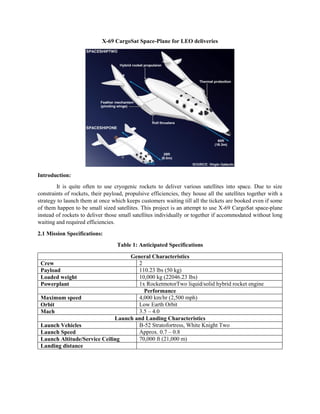
- 1. X-69 CargoSat Space-Plane for LEO deliveries Introduction: It is quite often to use cryogenic rockets to deliver various satellites into space. Due to size constraints of rockets, their payload, propulsive efficiencies, they house all the satellites together with a strategy to launch them at once which keeps customers waiting till all the tickets are booked even if some of them happen to be small sized satellites. This project is an attempt to use X-69 CargoSat space-plane instead of rockets to deliver those small satellites individually or together if accommodated without long waiting and required efficiencies. 2.1 Mission Specifications: Table 1: Anticipated Specifications General Characteristics Crew 2 Payload 110.23 lbs (50 kg) Loaded weight 10,000 kg (22046.23 lbs) Powerplant 1x RocketmotorTwo liquid/solid hybrid rocket engine Performance Maximum speed 4,000 km/hr (2,500 mph) Orbit Low Earth Orbit Mach 3.5 – 4.0 Launch and Landing Characteristics Launch Vehicles B-52 Stratofortress, White Knight Two Launch Speed Approx. 0.7 – 0.8 Launch Altitude/Service Ceiling 70,000 ft (21,000 m) Landing distance
- 2. 2.2 Mission Profile: Mission profile for X-69 will look similar to that of X-15 as shown in Fig. 1. There will be modifications after X-69 dives into the space, although its in-atmosphere is similar to that of X-15. Any mothership will help to air launch X-69. After detachment, it will burnout and climb towards LEO using RocketMotorTwo engine or similar ones. Fig 2. shows anticipated mission profile of X-69 CargoSat. Depending on mission it may spend variable amount of time in space either to just deploy and or wait for docking back another satellite. Re- entry will initiated as it drops into the atmosphere and will glide and land on airport. Fig. 1. Mission Profile of X-15
- 3. Fig 2. Estimated Mission profile of X-69 CargoSat 2.3 Market Analysis: Since a decade, concept of cubesats and other small satellites has been trending with a rising market. They deliver crucial advantages like compactness, multifunctional characteristics due to advanced technologies and highly efficient features. To date, rockets have been used to deliver these satellites into the space or orbits. Rockets are good to transport heavy and large instruments into the space. Although if a company or a customer wants to put their small-sized satellites to space, they have to wait or pay more price if they seek to launch through rockets. Moreover, it keeps them waiting till all other satellite companies collaborate for launch.
- 4. Reusable space-planes have capabilities to reach up to LEO and further. Small satellites can be delivered into space by space-planes with reusable capabilities. X-planes like Virgin Galactic’s Spaceship Two, X-15, X-37B can make return trips with crew inside. 2.4 Technical and Economic Feasibility Space-planes carrying human to space have been under research and even been flown quite many times. From technical perspective, it would be feasible to re-design the space-planes for satellite transport with reusability which essentially gives the benefit for aborted missions. These planes can also be used to bring back damaged or reparable satellites with efficient re-entry. Following points can be considered to propose the design of X-69 CargoSat: Based on payload and other avionics features, the design of X-69 will be similar to that been trending for Space-planes for human space flight. Air-launch will be same, using either B-52 Stratofortress or White Knight Two aircrafts. Will have to re-consider the aerodynamics for re-entry and landing aspects. Propulsion system will change based on payload, carrying satellites back and forth. Reusability is always an advantage for space transportation. Moreover, many attempts have been made and some of them are even successful to bring back rockets from space like SpaceX and Blue Origin. Although, this takes lot of fuel to fight with re-entry speeds and again to manage a perfect landing. It is quite easy for an airplane-like structure to land with less maintenance and accuracy. Again, space-planes would not need specific launch/landing pad. If X-69 brings reparable satellites from space, it can be delivered wherever it is necessary with less earth-transportation issues. It can land on any airport, deliver the satellite. For instance, let’s say a Chinese Space agency collaborates and asks American space agency who makes X-69 to bring back their damaged satellite, it will be easy and feasible to rendezvous X-69 to that satellite, dock it in, re-enter and land on any airport in China delivering the payload and flying back to home country. This will reduce ground transport cost, will not have to about damaged satellites and many other advantages. 2.5 Critical Mission Requirements: Following are the critical mission requirements that should be considered for design: Delta-wing design for re-entry and efficient landing. Efficient propulsion system for X-69 while air launching. Outer body material to deal with re-entry heat and high temperatures. Delta-wing pattern is quite traditional for supersonic aircrafts. Its design depends on requirements of aircraft and other technical specifications like altitude, speed, take-off and landing distance etc. Due to hypersonic speeds at re-entry, the surround atmospheric air heats up which is unfavorable for aircrafts with normal body material. Using carbon-composite makes it light-weight, resistant to high temperature and pressure and many other structural advantages.
- 5. 3.0 Comparative Study of Similar Airplanes: Table 2: Comparative study Parameters X-69 CargoSat Virgin Galactic’s Spaceship Two Boeing’s X-37 Boeing’s X-20 Dyna-Soar X-15 Crew 2 2 crew and 6 passengers none 1 pilot 1 pilot Takeoff/Launch weight 22,000 lb 21,428 lb (9,740 kg) 11,000 lb (4,990 kg) 11,387 lb (5,165 kg) 34,000 lb (15,420 kg) Empty weight 15,000 lb (6,804 kg) 15,000 lb (6,804 kg) NA (electric powered) 10,395 lb (4,715 kg) 14,600 lb (6,620 kg) Thrust 60,000 lbf to 75,000 lbf 60,000 lbf (270 kN) 157.4 lbf 700 kN) 72,000 lbf (323 kN) 70,400 lbf (313 kN) Critical Speed, Vcr 2,500 mph 2,500 mph (4,000 km/hr) (Orbital) 17,426 mph (28,440 km/h) 17,500 mph (28,165 km/hr) 4,520 mph (7,274 km/h) Range, R 300 mi and apogee of upto LEO of 160 – 250 km Planned apogee of 110 km Earth orbit 22,000 nm (40,700 km) 280 mi (450 km) Wing Area, S 345 ft2 (32 m2 ) 200 ft2 (18.6 m2 ) Wing span, b 27 ft (8.3 m) 14 ft 11 in (4.5 m) 20 ft 10 in (6.34 m) 22 ft 4 in (6.8 m) Aspect Ratio, AR 1.256 2.486 Type of Payload Crew and satellite Crew Satellites Crew Crew Powerplant 1x Rocket motorTwo liquid/solid hybrid rocket engine Gallium Arsenide Solar Cells with Li- Ion batteries 1x Transtage rocket engine 1x Reaction Motors XLR99-RM-2 liquid propellant rocket engine 3.3 Discussion: Various design The design of X-69 will be challenging from various aerospace aspects. There is quite a lot of versatility in comparing X-69 with other Space-planes considering their performance, general characteristics, applications, etc. As discussed, its launch weight will be similar to that of SpaceshipTwo of about 22,000 lb. From the comparison table, optimal thrust will be considered in the range of 60,000 to 75,000 lbf based on payload. X-15 using XLR99-RM-2 liquid propellant rocket engine manages to produce around 70,000 lbf of thrust which is enough to approach Mach 3 – 4. Anticipated body design of X-69 will be similar to that of X-15 and SpaceshipTwo with additional concentration on its body material and its efficiency for re-entry. Rocketmotor Two is an advanced powerplant that uses liquid/solid hybrid propellant which can reduce weight unlike X-15’s XLR99. Again mission requirements can vary after entering to the space based on altitude from earth, position of damaged satellite or position of undocking on-board satellites. An efficient re-entry system will allow X-69 simply glide and land back to base. This considers advanced aerodynamics characteristics and wing, tail and body parts along with its material, preferably a carbon composite.
- 6. 4.0 Conclusion and Recommendations: 4.1 Conclusion: X-69 will make satellite deliveries a lot easier and cost effective as compared to existing methods. Advanced technologies in electronics and computer have shrunk all the devices and have made them compact. This gives rise to high market for small-sized satellites or Cubesats. Using a space-planes like X- 69 or an existing SpaceshipTwo makes the system efficient. Also we don’t have to pollute space by disposing fairly working satellites. They can be brought back to earth, rework on it, modify the design and send it back to space using X-69. X-69 will be an efficient glider that will use its aerodynamics to reach the destination and safe landing. 4.2 Recommendations: Air launch has many developments since X-15 launched from B-52 Stratofortress and other missile launches from fighter jets. Motherships should have efficient performance to maintain launch altitude and launch speed. Motherships are expected to be sophisticated from structural point of view. Air launches are quite delicate while cruising with high speeds which might be vulnerable to structural integrity. Virgin Galactic uses central air launch mechanism for Spaceship Two. 5.0 References: https://www.globalaircraft.org/planes/x-15_hyper.pl https://en.wikipedia.org/wiki/North_American_X-15 http://www.mach25media.com/Resources/X15FlightLog.pdf http://er.jsc.nasa.gov/seh/ANASAGUIDETOENGINES%5B1%5D.pdf https://www.nasa.gov/centers/armstrong/news/FactSheets/FS-052-DFRC.html http://www.space.com/30245-x37b-military-space-plane-100-days.html http://www.af.mil/AboutUs/FactSheets/Display/tabid/224/Article/104539/x-37b-orbital-test-vehicle.aspx http://spaceflight101.com/spacecraft/x-37b-otv https://www.nasa.gov/centers/armstrong/news/FactSheets/FS-052-DFRC.html http://er.jsc.nasa.gov/seh/ANASAGUIDETOENGINES%5B1%5D.pdf http://www.ijee.ie/articles/Vol13-4/ijee950.pdf https://en.wikipedia.org/wiki/Boeing_X-37
- 7. 1 Configuration Design of X-69 CargoSat AE 271 – Aircraft Design Dr. Nikos Mourtos Rushikesh Badgujar San Jose State University Charles W. Davidson College of Engineering Aerospace Engineering
- 8. 2 Table of Contents 1. Introduction:..........................................................................................................................................3 2. Comparative Study: ..............................................................................................................................3 2.1 Configuration Comparison of Similar Airplanes:...............................................................................4 2.2 Discussion:..........................................................................................................................................7 3. Configuration Selection:...........................................................................................................................8 3.2 Wing Configuration:...........................................................................................................................9 3.3 Empennage Configuration: ...............................................................................................................11 3.4 Integration of the Propulsion system: ...............................................................................................11 3.5 Landing Gear Disposition:................................................................................................................11 3.6 Proposed configuration:....................................................................................................................12 4. References...............................................................................................................................................15
- 9. 3 1. Introduction: This report describes the configuration design for X-69. Based on mission requirements, it is necessary to propose a preliminary design which considers several aspects of aircraft like its general characteristics, overall configuration, wing configuration, propulsion system, landing gear disposition, etc. For initial guess, above parameters are referred to designs of similar aircrafts. X-planes like X-37B, VG Spaceship One, VG Spaceship Two, Boeing X-20 Dyna Soar, X-15 are considered for comparative study. 2. Comparative Study: After more research, I want to add SpaceShip One for comparative study. Table.1: Comparative study of similar airplanes Parameters Boeing’s X-37B Virgin Galactic’s Spaceship One Virgin Galactic’s Spaceship Two Boeing’s X-20 Dyna-Soar X-15 Crew none 1 pilot 2 crew and 6 passengers 1 pilot 1 pilot Takeoff/Launch weight 11,000 lb (4,990 kg) 21,428 lb (9,740 kg) 21,428 lb (9,740 kg) 11,387 lb (5,165 kg) 34,000 lb (15,420 kg) Empty weight NA (electric powered) 2,640 lb (1,200 kg) 15,000 lb (6,804 kg) 10,395 lb (4,715 kg) 14,600 lb (6,620 kg) Thrust 157.4 lbf 700 kN) 16534.67 lbf (74 kN) 60,000 lbf (270 kN) 72,000 lbf (323 kN) 70,400 lbf (313 kN) Critical Speed, V- cr (Orbital) 17,426 mph (28,440 km/h) 2,170 mph (3,518 km/hr) 2,500 mph (4,000 km/hr) 17,500 mph (28,165 km/hr) 4,520 mph (7,274 km/h) Range, R 675 days (longest flight) 40 mi (65 km) Planned apogee of 110 km Earth orbit 22,000 nm (40,700 km) 280 mi (450 km) Wing Area, S 161.4 ft2 (15 m2 ) 273.34 ft2 (25.4 m2 ) (estimated) 345 ft2 (32 m2 ) 200 ft2 (18.6 m2 ) Wing span, b 14 ft 11 in (4.5 m) 16 ft. 5 in (8.05 m) 27 ft (8.3 m) 20 ft 10 in (6.34 m) 22 ft 4 in (6.8 m) Aspect Ratio, AR 1.6 2.667 (estimated) 1.256 2.486 Type of Payload Satellites Pilot Crew Crew Crew Powerplant Gallium Arsenide Solar Cells with Li- Ion batteries 1x N2O/HTPB SpaceDev Hybrid rocket, 1x Rocket motorTwo liquid/solid hybrid rocket engine 1x Transtage rocket engine 1x Reaction Motors XLR99-RM-2 liquid propellant rocket engine
- 10. 4 2.1 Configuration Comparison of Similar Airplanes: a) Boeing’s X-37B: Fig.1: All views of Boeing X-37B b) Virgin Galactic’s Spaceship One: Fig.2: Front view Fig.3: Top view
- 11. 5 Fig.4: Side view c) Virgin Galactic’s Spaceship Two: Fig.5: Top and side view
- 12. 6 Fig.6: Front view with stabs trimmed up d) Boeing’s X-20 Dyna Soar: Fig.7: All views of X-20
- 13. 7 e) X-15: Fig. 8: All views of X-15A-2 with external fuel tank 2.2 Discussion: Following are the parameters that can have major impact on the design of X-69 as briefly discussed in report 1: As we can notice many facts are common in these aircrafts. Almost all the airplanes are designed to land back dealing with hypersonic speeds and gliding. Also they use motherships to air launch except X-37B which was launched using traditional rockets. Basically, a delta-wing pattern has been implemented on almost all the above designs with certain variations. Delta-wings give efficient performance at hypersonic speeds with better gliding as they descend.
- 14. 8 Low wing: X-37B, Spaceship Two, X-20 Dyna Soar Advantages: 1. Over-wing exits. 2. While in space, it is quite easy to deploy small satellites from upper fuselage where wing does not come in the way. 3. Easier to stick the main gear on. 4. Low wing doesn’t block any of the cabin. 5. Easy to access for maintenance and refueling. Med Wing: X-15A-2. (also its predecessor, X-15A) Advantages: 1. Med Wing provide best maneuverability. 2. Wing can be continuous through the fuselage. 3. Maintains structural integrity with the fuselage. High Wing: Spaceship One Advantages: 1. Quick loading and unloading. 2. Higher clearance from the ground providing less ground effect. A certain disadvantage of high wing has been documented especially for Spaceship One. The design was susceptible to roll excursions. It has been noticed that wind shear causes a large roll immediately after ignition progressing into multiple rapid rolls. Although as it gains high speed upon climb, this anomaly mitigates making the flight stable. 3. Configuration Selection: 3.1 Overall Configuration: X-69 will be a land based aircraft. A conventional type with Stabs and elevons. Fuselage Configuration: Spaceship Two and Spaceship One are built to accommodate 2 pilot and 6 – 8 crew with all facilities to deal with gravitational variations while climbing, in space and while descending. Design of X-69 fuselage will be conventional that seeks to accommodate satellites with sophisticated mechanisms to deploy or undock satellites into LEO or dock back returning satellites without any damage to either X-69 or satellite. Deployment systems like NanoRacks CubeSat Deployer (NRCSD) or XPOD Separation System can be used based on the layout of racks and fuselage design. Direction of deployment can be from sideways or rear since wing can be moved up or down with relatively less effect on X-69 maneuvering.
- 15. 9 3.2 Wing Configuration: These type of planes have relatively different wing patterns unlike traditional airplanes. Wing design of both Spaceship One and Two are standard and similar consisting Elevons and Stabilator. Based on advantages of low wing position, X-69 will have Low wing. Wing will be aft swept with certain angle. This design will not necessarily require winglets due to presence of elevons and stabilators. The horizontal stabilizer design for X-69 may lie between dual tail and twin tail. Similarly, vertical tails will be connected and operated electrically on each tip of the horizontal tail to control yaw and roll. Elevons: Like traditional airplanes, elevons are aircraft control surfaces that combine the functions of elevator that controls pitch and aileron that controls roll. For above aircrafts, elevons are located behind the stabilator (also called as stab) directly connected to the stick in the cockpit using cables. Stabilator: Stabilator, also called as stab, is fully movable aircraft stabilizer. Besides its usual function to stabilize longitudinally, it is very useful device at high Mach number for changing the aircraft balance within wide limits and for mastering the stick forces. In case of X-69, stab will control pitch when trimmed up or down using electromechanical device and will control roll when moved independently. Airfoils used for Wings: X-69 like other X-planes does not need much of aerodynamics while climbing from around 45,000 ft to 50,000 ft. The climb is solely governed by rocket motor which takes barely 10-15 minutes to reach LEO. Ion Thrusters can be installed for efficient maneuver while in space. Efficient airfoil selection will play vital role in returning phase and re-entry. X-69 will glide as it descends after re-entry with required loitering to decelerate followed by landing approach. In the first test flight of Spaceship One, landing procedure used modified version of a standard engine out approach that is generally used by the military. HS 130 airfoil popular for dynamic soaring can be used for wing to obtain efficient glide. From the research it is found that HS 130 delivers very less drag and has characteristics of slope soaring. This airfoil is also used for elevons with 25% chord. As shown in Fig.9 and Fig.10, the study has been done on HS 130 airfoil using Xfoil analyzing pressure distribution, lift, drag and moment coefficients. Fig.10 considers various angle of attacks from -2o to 6o at zero Mach for initial analysis.
- 16. 10 Fig.9: Cp at 6 deg of AoA with boundary layer Fig.10: Pressure distribution Cp at various AoA’s
- 17. 11 3.3 Empennage Configuration: As discussed earlier, the stabs and elevons will be controlled using electromechanical system. Although, it is very important to pick the efficient configuration for better performance specially to glide, loiter if necessary and safe landing. From the research so far, there are three options such as Tailplane mounted, Twin tail boom or Wing mounted as shown in Fig. 11. For initial guess and referring to previous designs, wing mounted configuration can be picked. Fig.11: Empennage configurations 3.4 Integration of the Propulsion system: Engine type: Rocket Motor engine Engine Integration: Engine inside the fuselage from behind. This is a X-type of plane that uses rocket motors for propulsion. For X-69, we seek to use solid/liquid hybrid propellant rocket that can deliver thrust in the range of 60,000 lbf to 75,000 lbf. X-15 uses XLR99- RM-2 liquid propellant rocket engine. Although this system makes it quite bulky to handle liquid propellants and sloshing issues. On the other hand, Virgin Galactic and Scaled Composites used hybrid rocket motor with benign fuel and oxidizer. The advantage of hybrid rocket motor is that it is controllable and can be shut down at any time during boost phase of flight. It has less issues with sloshing. As a new requirement, it seems necessary to use Reaction Control System(RCS) thrusters on small scale for in-space maneuverability, attitude control to efficiently undock/dock satellites from X-69. 3.5 Landing Gear Disposition: Landing Gear: Retractable gear Nose-wheel landing gear Landing gear integration: In the fuselage Rear gears attached to wings retracting inwards.
- 18. 12 3.6 Proposed configuration: Basic design of X-69 is almost similar to that of Spaceship Two. Although, based on requirements such as, ground effects, type of propulsion system, docking/undocking mechanisms, design of fuselage will be slightly different. As proposed earlier, fuselage will have sideway doors to deploy satellites from upwards which is why low wing has been chosen. Placement of RCS thrusters has not decided yet which is required for maneuver in space to conveniently operate docking/undocking. Using Solidworks, following is the preliminary design of X-69 as shown in figures, 12,13,14,15,16 from various orientation and angles. Due to time constraints, the design is missing complete tail which is of on-wing mounted type, proportionate size of fuselage, landing gears pockets for retraction, etc. HS 130 airfoil has been used for wing and tail modelling. Fig. 12: Isometric 3-D view of X-69
- 19. 13 Fig. 13: Front view of X-69 Fig. 14: Rear view of X-69
- 20. 14 Fig. 15: Side view of X-69 Fig. 16: Top view of X-69
- 21. 15 4. References (n.d.). Retrieved from http://www.petervis.com/interests/published/Spaceshiptwo/Spaceshiptwo_Rocket.html. (n.d.). Retrieved from http://www.nbcnews.com/storyline/virgin-voyage/how-spaceshiptwos-feathered- wings-were-supposed-work-n240256. (n.d.). Retrieved from http://bagera3005.deviantart.com/art/White-Knight-SpaceShip-One-158659309. (n.d.). Retrieved from https://en.wikipedia.org/wiki/SpaceShipOne. Airfoil Database. (n.d.). Retrieved from https://www.aerodesign.de/english/profile/profile_s.htm. Airfoils and Airflow. (n.d.). Retrieved from https://www.av8n.com/how/htm/airfoils.html. Donald Greer, hamory, P., Krake, K., & Drela, M. (n.d.). Design and Predictions for a High-Altitude (Low-Reynolds-Number) Aerodynamic Flight Experiment. Evans, M. (2013). The X-15 Rocket Planes. In M. Evans, The X-15 Rocket Planes. FAA. (n.d.). Aerodynamics of Flight. In Gliding Flight Handbook. Flight Training Center. (n.d.). Retrieved from http://flighttrainingcenters.com/training-aids/multi- engine/engine-out-procedures/. Global Aircraft. (n.d.). Retrieved from https://www.globalaircraft.org/planes/x-15_hyper.pl. https://en.wikipedia.org/wiki/North_American_X-15. (n.d.). Retrieved from https://en.wikipedia.org/wiki/North_American_X-15. NASA. (n.d.). A NASA Guide to engines. NASA factsheet. (n.d.). Retrieved from https://www.nasa.gov/centers/armstrong/news/FactSheets/FS-052- DFRC.html. Scaled Composites. (n.d.). Retrieved from http://www.scaled.com/projects/tierone/. Space Flight Laboratory. (n.d.). Retrieved from http://utias-sfl.net/?page_id=87. Space.com. (n.d.). Retrieved from http://www.space.com/30245-x37b-military-space-plane-100- days.html. Virgin Galactic. (n.d.). Retrieved from http://www.virgingalactic.com/human-spaceflight/our-vehicles/. Virgin galactic fact sheet. (n.d.). Retrieved from http://www.galacticexperiencesbydeprez.com/pdf/vg_vehicles_fact_sheet101411.pdf. wired.com. (n.d.). Retrieved from https://www.wired.com/2010/10/test-pilot-describes-first-glide-flight- of-spaceshiptwo/.
- 22. 1 Weight Sizing and Weight Sensitivities of X-69 CargoSat AE 271 – Aircraft Design Dr. Nikos Mourtos Rushikesh Badgujar San Jose State University Charles W. Davidson College of Engineering Aerospace Engineering
- 23. 2 Index 1. Introduction 3 2. Mission Weight Estimates 3 2.1.Database for Takeoff Weights and Empty Weights of Similar Airplanes 3 2.2.Determination of Regression Coefficients A and B 3 2.3. Determination of Mission Weights 5 2.3.1. Manual Calculation of Mission Weights 6 2.3.2. Calculation of Mission weights using the AAA program 9 3. Takeoff Weight Sensitivities 12 3.1.Manual Calculation of Takeoff Weight Sensitivities 12 3.2.Calculation of Takeoff Weight Sensitivities using the AAA program 16 3.3. Trade studies 17 4. Discussion 19 5. Conclusions and Recommendations 21 5.1.Conclusions 21 5.2.Recommendations 21 6. References 22 7. Appendices 23
- 24. 3 1. Introduction: The mission profile of X-69 divides its flight into two phases. X-69 makes an air launch and climbs at supersonic speed in Phase I. This phase will last for about 90 seconds in which X-69 will reach to altitude of about 360,000 ft (110 km) at Mach 3.0 – 3.5. Deploying the payload (satellites) into space and docking back returning satellites if required by mission, it will descend and land using its gliding characteristics decelerating itself to subsonic speeds in Phase II. X-69 will have reaction control system such as RV-105 RCS Thruster block or Vernor Engine to control transcend between phase I and II. These thrusters use very less fuel to maintain the required thrust in x, y and z direction for maneuvering and attitude control. In phase I for weight analysis, we consider supersonic cruise fuel-fraction for initial calculations. In phase II for weight analysis, we consider sail plane fuel-fraction which eventually is similar to small home built airplanes. 2. Mission Weight Estimates: 2.1. Database for Takeoff Weights and Empty Weights of Similar Airplanes: Table 2.1 provides a database for takeoff and empty weights of similar airplanes. Boeing X-37B is an exception since this ROT vehicle is electric powered which has same empty weight as takeoff. Table 2.1: Database for Takeoff weights and empty weights of Similar Airplanes Airplane Type Takeoff Weight Empty Weight Lockheed CL-1200 Lancer Supersonic 35,000 lbs (15,900 kg) 17,885 lbs (8,112 kg) Martin Marietta X-24B Supersonic 13,800 lbs (6,260 kg) 8,500 lbs (3,855 kg) Virgin Galactic Spaceship One Supersonic 10,560 lbs (4,800 kg) 2,640 lbs (1,200 kg) Virgin Galactic Spaceship Two Supersonic 21,428 lbs (9,740 kg) 10,423 lbs (4,272.8 kg) Boeing X-20 Dyna Soar Supersonic 11,387 lbs (5,165 kg) 10,395 lbs (4,715 kg) North American X-15 Supersonic 34,000 lbs (15,420 kg) 14,600 lbs (6,620 kg) Lockheed Martin X-33 suborbital spaceplane 285,000 lbs (129,000 kg) 75,000 lbs (34,019.43 kg) NASA X-38 CRV re-entry vehicle 54,500 lbs (24,721 kg) 23,500 lbs (10,660 kg) Douglas X-3 Stiletto Supersonic 23,840 lbs (10,810 kg) 16,120 lbs (7,310 kg) Ryan X-13 Vertijet VTOL jet aircraft 7,200 lbs (3,272 kg) 5,334 lbs (2,424 kg) Boeing X-37B Reusable Orbital Test vehicle 11,000 lbs (4,990 kg) 11,000 lbs (4,990 kg) North American X-10 cruise missile 42,300 lbs (19,187 kg) 25,800 lbs (11,703 kg) Boeing X-40 Reusable launch vehicle 3,700 lbs (1,640 kg) 2,500 lbs (1,100 kg) 2.2. Determination of Regression Coefficients A and B: Before initiating the calculation for determination of mission weights and empty weight, it is necessary to make an initial guess for takeoff weight based on similar airplanes take off weight data. Fig. 1 is the plot of empty weight v/s takeoff weight of similar airplanes as tabulated in table.1. Initial takeoff weight can be guessed close to trend line. For X-69 the payload weight will be 14,000 lbs, similar to that of Spaceship Two.
- 25. 4 Fig. 1: Weight trends for Space-planes Fig. 2: log-log plot of weight data It is necessary to determine regression coefficients A and B for X-69. Fig.2 is a log-log plot of weight data of similar airplanes that are considered. Equation of trend line will give regression coefficients A and B as follows: Equation of trend line is: 𝑦 = 0.8613. 𝑥 + 0.3651 In this case, y = log10(WE) x = log10(WTO) X-69 CargoSat 0 5000 10000 15000 20000 25000 30000 0 10000 20000 30000 40000 50000 60000 EmptyWeight,WE,lbs Gross Take-off weight,WTO , lbs Weight Trends for Space-planes X-69 y = 0.8613x + 0.3651 3 3.2 3.4 3.6 3.8 4 4.2 4.4 4.6 3 4 5 log10(WE) log10(WTO) log10(WE) v/s log10(WTO)
- 26. 5 from equation 2.16 in Roskam, 𝑊𝐸 = 10 { log(10) 𝑊 𝑇𝑂−𝐴 𝐵 } Simplifying above equation, we get Log10(𝑊𝐸) = 1 𝐵 log10 𝑊𝑇𝑂 − 𝐴 𝐵 Therefore, 1 𝐵 = 0.8613 𝐵 = 1.161 And − 𝐴 𝐵 = 0.3651 𝐴 = −0.424 Hence we find the regression coefficients as A = -0.424 and B = 1.161. 2.3. Determination of Mission Weights: There are two methods such as manual calculation and using AAA program to determine mission weights. Both methods begin by guessing a takeoff weight followed by sequential phases of flight like engine start and warmup, taxi, takeoff, climb, loiter if necessary, descent and approach and landing. The methods are described as follows: 𝑊𝑡𝑎𝑘𝑒𝑜𝑓𝑓 = 32,000 𝑙𝑏𝑠 (𝐺𝑢𝑒𝑠𝑠) As discussed, X-69 flight consists of two phases in its complete flight. It will make an air launch from mothership with a clean release and climb at supersonic speed. Although while descending and landing X-69 will glide decelerating to subsonic speed using aerodynamics and efficient wing configuration. Hence fuel-fractions will be considered according to the mission phase of the flight. Subsonic glide fuel fractions are average of fuel-fractions of light weight aircrafts like Homebuilt, Single Engine, Twin Engine and Agricultural airplanes. Highlighted section of table 2.2 are the fuel-fractions considered for two phases of X-69 flight and hence to calculate its takeoff weight. Referring to table 2.1. Suggested Fuel-fractions for Several Mission Phases in Roskam book, Table 2.2. Suggested Fuel-fractions for Several Mission Phases Mission Phase Engine start Takeoff/Air launch Climb Descent Landing, Taxi and Shutdown Supersonic Cruise 0.990 0.995 0.92-0.87 0.985 0.992 Subsonic Glide 0.995 0.997 0.994 0.993 0.995 Referring to Table 2.15. Regression Line Constants A and B in Roskam, regression coefficients A and B are 0.4221 and 0.9876 respectively since X-69 will be in supersonic flight.
- 27. 6 2.3.1.Manual Calculation of Mission Weights: The fuel-fraction, mff for each phase is defined as the ratio of end weight to begin weight. The next step is to assign a numerical value to the fuel-fraction corresponding to each mission phase. This is done as follows referring to table. 2.2: Phase 1. Engine Start and warm up: Begin weight is WTO. End weight is W1. The fuel fraction for this phase is by definition given by: W1/WTO. Therefore, 𝑓𝑢𝑒𝑙 − 𝑓𝑟𝑎𝑐𝑡𝑖𝑜𝑛 = 𝑊1 𝑊𝑇𝑂 0.990 = 𝑊1 32,000 𝑙𝑏𝑠 𝑊1 = 31,680 𝑙𝑏𝑠 Phase 2. Clean Release, Air launch/Take off: Begin weight is W1. End weight is W2. The fuel fraction for this phase is W2/W1. Therefore, 𝑓𝑢𝑒𝑙 − 𝑓𝑟𝑎𝑐𝑡𝑖𝑜𝑛 = 𝑊2 𝑊1 0.995 = 𝑊2 31,680 𝑙𝑏𝑠 𝑊2 = 31,521.6 𝑙𝑏𝑠 Phase 3. Climb at Supersonic speed: Begin weight is W2. End weight is W3. The fuel fraction for this phase is W3/W2. To calculate fuel-fraction for climb, we need to know following parameters: Change in altitude, ∆ℎ Rate of climb L/D ratio Specific fuel consumption, cj Therefore, 𝑓𝑢𝑒𝑙 − 𝑓𝑟𝑎𝑐𝑡𝑖𝑜𝑛 = 𝑊3 𝑊2 0.9951 = 𝑊3 31,521.6 𝑙𝑏𝑠
- 28. 7 𝑊3 = 31367.14 𝑙𝑏𝑠 Phase 4. Drop from the space and descent towards earth from 80,000 ft: Begin weight is W4. End weight is W3. The fuel fraction for this phase is W4/W3. Therefore, 𝑓𝑢𝑒𝑙 − 𝑓𝑟𝑎𝑐𝑡𝑖𝑜𝑛 = 𝑊4 𝑊3 0.993 = 𝑊4 31,367.14 𝑙𝑏𝑠 𝑊4 = 31,147.57 𝑙𝑏𝑠 Phase 5. Approach, Landing, Taxi and shutdown: Begin weight is W5. End weight is W4. The fuel fraction for this phase is W5/W4. Therefore, 𝑓𝑢𝑒𝑙 − 𝑓𝑟𝑎𝑐𝑡𝑖𝑜𝑛 = 𝑊5 𝑊4 0.995 = 𝑊5 31,147.57 𝑙𝑏𝑠 𝑊5 = 30,991.84 𝑙𝑏𝑠 Therefore, the mission fuel-fraction, Mff is given as: 𝑀𝑓𝑓 = ( 𝑊1 𝑊𝑇𝑂 ) ∗ ∏ ( 𝑊𝑖+1 𝑊𝑖 ) 𝑖=5 𝑖=1 𝑀𝑓𝑓 = ( 𝑊1 𝑊𝑇𝑂 ) ( 𝑊2 𝑊1 ) ( 𝑊3 𝑊2 ) ( 𝑊4 𝑊3 ) ( 𝑊5 𝑊4 ) 𝑀𝑓𝑓 = ( 𝑊5 𝑊𝑇𝑂 ) 𝑀𝑓𝑓 = ( 30,991.84 32,000 ) 𝑀𝑓𝑓 = 0.9685 Weight of fuel used, Wf_used 𝑊𝐹 𝑢𝑠𝑒𝑑 = (1 − 𝑀𝑓𝑓)𝑊𝑇𝑂 𝑊𝐹 𝑢𝑠𝑒𝑑 = (1 − 0.9685) × 32,000
- 29. 8 𝑊𝐹 𝑢𝑠𝑒𝑑 = 1,008 𝑙𝑏𝑠 A = -0.424, B = 1.161 𝑊𝐸 = 10(log10 𝑊 𝑇𝑂−𝐴)/𝐵 𝑊𝐸 = 10 log10 32,000+0.424 1.161 𝑊𝐸 = 17,603.8 𝑙𝑏𝑠 A tentative value for WOE is found from equation below: 𝑊𝑂𝐸_𝑡𝑒𝑛𝑡 = 𝑊𝑇𝑂 − 𝑊𝐹 𝑢𝑠𝑒𝑑 − 𝑊𝑃𝐿 Payload weight, WPL is 14,000 lbs. 𝑊𝑂𝐸_𝑡𝑒𝑛𝑡 = 32,000 − 1,008 − 14,000 𝑊𝑂𝐸_𝑡𝑒𝑛𝑡 = 16,992 𝑙𝑏𝑠 A tentative value for WE is found from equation below: 𝑊𝐸𝑡𝑒𝑛𝑡 = 𝑊𝑂𝐸𝑡𝑒𝑛𝑡 − 𝑊𝑇𝐹𝑂 − 𝑊𝑐𝑟𝑒𝑤 𝑊𝑇𝐹𝑂 = 0.005 × 𝑊𝑇𝑂 = 0.005 × 32,000 𝑊𝑇𝐹𝑂 = 160 𝑙𝑏𝑠 𝑊𝐸𝑡𝑒𝑛𝑡 = 16,992 − 160 − 350 𝑊𝐸𝑡𝑒𝑛𝑡 = 16482 𝑙𝑏𝑠 Comparing WE-tent and WE-allowable/ WE, |𝑊 𝐸−𝑊 𝐸 𝑡𝑒𝑛𝑡| 𝑊 𝐸+𝑊 𝐸 𝑡𝑒𝑛𝑡 2 = |17,603.8−16482| 17,603.8+16482 2 × 100 = 6.583% Using MATLAB, WTO can be iterated to obtain required comparison less than 0.5%. The code can be referred from Appendix C. After iterating, WTO = 34,200 lbs gives comparison percentage of about 0.214% which is less than 0.5% with empty weight, WE = 18,641.42 lbs. Table. 3: mission weights with respect to selected takeoff weight = 34,200 lbs Engine start and warmup, w1 33858.0 lbs Air launch/ takeoff, w2 33688.7 lbs Climb, w3 33523.6 lbs Descent, w4 33289.0 lbs Land and taxi, w5 33122.5 lbs Weight of fuel used, Wf 1077.33 lbs
- 30. 9 2.3.2.Calculation of Mission weights using the AAA program: Before starting the calculation for take-off weight, it is necessary to set up the configuration of X- 69 in the software. Appendix D shows initial steps to set the parameters and configuration of aircraft: In AAA program, after configuring X-69, we start with weight analysis by defining mission profile and respective fuel-fractions. Fig. 3 shows sequentially arranged segment-wise mission profile with required fuel-fractions: Fig. 3. Mission profile of X-69 with fuel-fraction. After mission profile is defined, we obtain regression coefficients based of empty and takeoff weights of similar airplanes that are accounted in table.1. Clicking on “Weight Sizing” opens following window as shown in Fig. 4 where user needs to feed in similar airplanes data as I did it for X-69. It is necessary to maintain the airplane data less scattered. The more the airplanes, more will be the accuracy for regression coefficients. For X-69, I found up to 11 similar airplanes that were considered to compute regression coefficients and will be used to compute takeoff weight in next step. Fig. 5 is shows the trend line for empty weight v/s takeoff weight from which regression coefficients were obtained.
- 31. 10 Fig. 4. Regression coefficients A and B Fig. 5. Regression plot and trend line
- 32. 11 After obtaining regression coefficients A and B, it is safe to proceed for takeoff weight. We input required parameters in “Take-off weight: Flight condition 1” window as shown in Fig. 6. We input same regression coefficients A and B that we obtained in previous step. Any near-takeoff weight can be guessed under WTOest. There are no passengers in X-69 but 2 pilots weighing approximately 175 lbs each. Rest of the payload of satellites have been considered under Wcargo = 14,000 lbs. Fuel fraction of trapped fuel and oil is assumed to be 0.005% as referred from Roskam. X-69 won’t need any reserve fuel, so Mres=0. After hitting calculate, it gives following output parameters with slightly different value of takeoff weight than that obtained from manual calculation. Fig. 7 shows the design point for takeoff weight using the same equations that were used to perform manual calculations. AAA program gives WTO as design point equal to 36505.2 lbs which is little higher number than that obtained from manual calculation with WTO = 34,200 lbs. Fig. 6. Takeoff weight: Flight condition 1.
- 33. 12 Fig. 7. Design point on trend line @ 36505.2 lbs 3. Takeoff Weight Sensitivities: 3.1. Manual Calculation of Takeoff Weight Sensitivities: Before starting sensitivity calculations, it should be checked if equation 2.24 from Roskam yields approximately same takeoff weight, WTO as we obtained from iterative method in section 2.3. To do that we can substitute values of regression coefficients A, B, C and D in equation 2.24 as stated below: log10 𝑊𝑇𝑂 = 𝐴 + 𝐵 log10(𝐶. 𝑊𝑇𝑂 − 𝐷) Substituting A=-0.424, B=1.161, C=0.9635 and D=14,350 lbs and using small matlab solver from Appendix C, we get log10 𝑊𝑇𝑂 = −0.424 + 1.161 × log10(0.9635 × 𝑊𝑇𝑂 − 14,350) 𝑊𝑇𝑂 = 34,280.4 𝑙𝑏𝑠 WTO that we just obtained is quite close to th`at we got from iterative method, hence we can move ahead with this takeoff weight for sensitivity calculations. X-69 will not be cruising at any time throughout its flight since it will climb at supersonic speed as it drops from mothership. Hence there is no cruise consideration while calculating sensitivities either in AAA program. After preliminary sizing, it is mandatory to conduct sensitivity studies on parameters such as
- 34. 13 Payload, WPL: Sensitivity of Take-off weight to Payload Weight: From section 2.7.2 Sensitivity of Take-off weight to Payload weight of Roskam, sensitivity of take-off weight to payload weight is given by: 𝜕𝑊𝑇𝑂 𝜕𝑊𝑃𝐿 = 𝐵. 𝑊𝑇𝑂/(𝐷 − 𝐶(1 − 𝐵). 𝑊𝑇𝑂)⁄ 𝐴 = −0.424, 𝐵 = 1.161 𝐶 = {1 − (1 + 𝑀𝑟𝑒𝑠)(1 − 𝑀𝑓𝑓) − 𝑀𝑡𝑓𝑜} 𝑊𝐹𝑟𝑒𝑠 = 𝑀𝑟𝑒𝑠. (1 − 𝑀𝑓𝑓). 𝑊𝑇𝑂 𝑀𝑟𝑒𝑠 = (𝑊𝐹𝑟𝑒𝑠 /((1 − 𝑀𝑓𝑓). 𝑊𝑇𝑂)) No reserves, therefore 𝑀𝑟𝑒𝑠 = 0 𝐶 = {1 − (1 + 𝑀𝑟𝑒𝑠)(1 − 𝑀𝑓𝑓) − 𝑀𝑡𝑓𝑜} 𝐶 = {1 − (1 + 0)(1 − 0.9685) − 0.005} 𝐶 = 0.9635 𝐷 = 𝑊𝑃𝐿 + 𝑊𝑐𝑟𝑒𝑤 𝐷 = 14,000 + 350 𝐷 = 14,350 𝑙𝑏𝑠 𝜕𝑊𝑇𝑂 𝜕𝑊𝑃𝐿 = 𝐵. 𝑊𝑇𝑂/(𝐷 − 𝐶(1 − 𝐵). 𝑊𝑇𝑂)⁄ 𝜕𝑊𝑇𝑂 𝜕𝑊𝑃𝐿 = 1.161 × 34,280.4 14,350 − 0.9635(1 − 1.161) × 34,280.4 ⁄ 𝜕𝑊𝑇𝑂 𝜕𝑊𝑃𝐿 = 2.021⁄ This means that for each pound of payload added, the airplane take-off gross weight will have to be increased by 2.021 lbs and is called growth factor due to payload for X-69. Empty weight, WE Sensitivity of Take-off weight to Payload Weight: From section 2.7.3, Sensitivity of Take-off weight to Empty weight of Roskam, sensitivity of take-off weight to payload weight is given by: 𝜕𝑊𝑇𝑂 𝜕𝑊𝐸 = 𝐵𝑊𝑇𝑂 [10{(log10 𝑊 𝑇𝑂−𝐴)/𝐵}] ⁄ 𝜕𝑊𝑇𝑂 𝜕𝑊𝐸 = 1.161 × 34,280.4 [10{(log10 34,280.4+0.424)/1.161}] ⁄ 𝜕𝑊𝑇𝑂 𝜕𝑊𝐸 = 2.13⁄ For each lb of increase in empty weight, the take-off weight will increase by 2.13 lbs and is a growth factor due to empty weight for X-69.
- 35. 14 Range, R Sensitivity of Take-off weight to Range: Estimated range of X-69 is 120nm (110 km) return trip including re-entry and landing. X- 69 will climb at supersonic speed and hence the characteristics for calculating sensitivities of take- off weight and range will be similar to that of fighter airplanes. From It is necessary to calculate a factor F using equation 2.44 in Roskam as given below: 𝐹 = −𝐵. 𝑊𝑇𝑂 2 {𝐶𝑊𝑇𝑂. (1 − 𝐵) − 𝐷} × (1 + 𝑀𝑟𝑒𝑠)𝑀𝑓𝑓 Substituting values of B, C, D in above equation. 𝐹 = −1.161 × 34,280.42 {0.9635 × 34,280.4 × (1 − 1.161) − 14,350} × 0.9685 𝐹 = 67184.66 𝜕𝑊𝑇𝑂 𝜕𝑅 = 𝐹𝑐𝑗 𝑉𝐿 𝐷 considering cruise out numbers for X-69 from Roskam, 𝑐𝑗 = 1.25, 𝑉 = 459 𝑘𝑡𝑠 (𝑠𝑢𝑝𝑒𝑟𝑠𝑜𝑛𝑖𝑐, 3186 𝑘𝑚 ℎ𝑟 = 𝑀𝑎𝑐ℎ 3.0) , 𝐿 𝐷 = 7: 1 Therefore, 𝜕𝑊𝑇𝑂 𝜕𝑅 = 67184.66 × 1.25 3186 𝑘𝑚/ℎ𝑟 × 7 𝜕𝑊𝑇𝑂 𝜕𝑅 = 3.766 𝑙𝑏𝑠/𝑘𝑚 Hence for every increase of in kilometer, gross take-off weight will increase by 3.766 lbs. Endurance, E Sensitivity of Take-off weight to Endurance: Same as Range, sensitivity of takeoff weight to endurance is given by 𝜕𝑊𝑇𝑂 𝜕𝐸 = 𝐹𝑐𝑗 𝐿 𝐷 𝜕𝑊𝑇𝑂 𝜕𝐸 = 67184.66 × 1.25 7 𝜕𝑊𝑇𝑂 𝜕𝐸 = 11997.26 𝑙𝑏𝑠/ℎ𝑟
- 36. 15 Lift-to-drag ratio, L/D Sensitivity of Take-off weight to Lift-to-drag ratio with respect to range requirement: 𝜕𝑊𝑇𝑂 𝜕 ( 𝐿 𝐷) = − 𝐹𝑅𝑐𝑗 𝑉 ( 𝐿 𝐷) 2 𝜕𝑊𝑇𝑂 𝜕 ( 𝐿 𝐷) = − 67184.66 × 94.488 𝑘𝑚 × 1.25 3186 𝑘𝑚/ℎ𝑟 × 72 X-69 will use fuel only while climbing. As said earlier, it will just glide while descending without any use of fuel. Hence range, R in above equation is taken only when it is climbing from 50,000 ft to 360,000 ft which gives 94.488 km of climb. Hence, 𝜕𝑊𝑇𝑂 𝜕 ( 𝐿 𝐷) = −50.83 𝑙𝑏𝑠 If the lift-to-drag ratio of the airplane were 16 instead of the assumed 14, the design take- off gross weight would decrease by 16-14=2× 50.83=101.66 lbs. Specific fuel consumption, cj Sensitivity of Take-off weight to specific fuel consumption, cj with respect to range requirement: 𝜕𝑊𝑇𝑂 𝜕𝑐𝑗 = 𝐹𝑅 𝑉 𝐿 𝐷 𝜕𝑊𝑇𝑂 𝜕𝑐𝑗 = 67184.66 × 94.488 𝑘𝑚 3186 𝑘𝑚/ℎ𝑟 × 7 𝜕𝑊𝑇𝑂 𝜕𝑐𝑗 = 284.64 𝑙𝑏𝑠 𝑙𝑏𝑠 /( 𝑙𝑏𝑠 ℎ𝑟 ) If specific fuel consumption was incorrectly assumed to be 0.5 and in reality turns out to be 0.9, the design take-off gross weight will increase by 0.9-0.5=0.4× 284.64=113.86 lbs. 3.2. Calculation of Takeoff Weight Sensitivities using the AAA program: AAA program provides sensitivity computation if required parameters have been inserted. If sequential procedure is followed, i.e starting with mission profile, obtaining regression coefficients and hence takeoff weight, then sensitivity automatically considers those basic parameters. Hitting calculate button gives sensitivities of takeoff weight with payload, empty weight, range, specific fuel consumption, L/D ratio and endurance.
- 37. 16 Since X-69 will never cruise neither loiter, there is no takeoff sensitivity with respect to range. As stated earlier, after completing its mission in space it will be dropped towards earth with accurate attitude using reaction control system. As it reaches 80,000 – 85,000 ft, it will use its wing and aerodynamics to slow down and glide to destination. Although its total range will be 120 nm considering return trip excluding cruising, loitering phase of flight. Fig. 8. Sensitivity calculation and growth factors. There is significant percentage difference between manually calculated and AAA computed sensitivities. Regression coefficients A and B are the major cause responsible for this difference. It is unclear that what method does AAA program use to calculate regression coefficients A and B using same similar airplane database and hence trend line that is been used for manual calculation. Although from the linear characteristics and using method described in Roskam Book, we obtain different A and B for manual calculations than from AAA program. Table. 5 describes the percentage difference which on an average is up to 30%. 3.3. Trade Studies: As discussed earlier, X-69 will never cruise or loiter in its flight. Hence trade studies of Range, R and other parameters were not performed. Although, trade studies were performed for other significant parameters that are required for X-69 such as specific fuel consumption, rate of climb, payload, etc. As asked, while performing trade studies, takeoff weight has been kept constant throughout. AAA program is used for trade studies. Table. 4 shows the trade study. Certain amount of payload has to be traded-off for increase specific fuel consumption to accommodate more fuel at certain climb rate keeping the takeoff weight constant. Also we can see that if X-69 needs to climb faster, specific fuel consumption has to be increased reducing the payload weight. Fig. 9 shows the plot of trade study. If X-69 seeks for higher specific fuel consumption, payload has to be reduced depending on the climb rate. This method can be used to read above plot and is explained below:
- 38. 17 For instance, say X-69 is climbing at rate of 150,000 ft/min with payload of 14,000 lbs, from plot, it will need 0.9 lb/hr/lb of fuel shown by blue line in Fig. 10. Now if owner wants X-69 to climb at higher rate, say 200,000 ft/min keeping the same payload of 14,000 lbs and takeoff weight which is already constant, it will have to consume approximately 1.275 lb/hr/lb of fuel shown by red line in Fig. 10. At the same time, if owner changes his mind and wants to reduce climb rate to 150,000 ft/min back again then payload has to be reduced to approximately 13,925 lbs gaining more specific fuel consumption. Table. 6: Trade study of payload with specific fuel consumption and rate of climb rate of climb, ft/min 150000 200000 250000 300000 Takeoff weight, WTO, lbs specific fuel consumption, cj, lb/hr/lb Payload weight, WPL, lbs 36505.1 0.6 14050.35 14077.15 14089.6 14099.3 36505.3 0.7 14039.9 14065.35 14079.75 14091.15 36505.1 0.8 14017.5 14053.4 14069.85 14083.25 36505.1 0.9 14001.15 14041.5 14060 14074.8 36505.1 1 13984.9 14029.65 14050.25 14066.6 36505.1 1.1 13968.57 14017.75 14040.5 14058.35 36505.2 1.2 13952.15 14005.95 14030.55 14050.3 36505 1.3 13935.9 13994 14020.75 14042 36505.2 1.4 13920.55 13982.2 14011 14033.9 36505.2 1.5 13903.3 13970.35 14001.15 14025.65 Fig. 9: Trade study of payload with specific fuel consumption and rate of climb Design Point 13850 13900 13950 14000 14050 14100 14150 0.5 0.7 0.9 1.1 1.3 1.5 1.7 payloadweight,WPL,lbs specific fuel consumption, cj , lb/hr/lb Trade study of payload weight vs specific fuel consumption with takeoff weight constant 150000 ft/min 200000 ft/min 250000 ft/min 300000 ft/min
- 39. 18 Fig.10: Method example to read the trade study plot. Red dot in fig. 9 can be good design point where we get to increase payload by around 25 lbs maintaining climb rate of 200,000 ft/min but trading off fuel consumption by around 0.15 lb/hr/lb which is not much since climb time is hardly 2 minutes. At this design point, X-69 will travel at Mach 3.0. 4. Discussion: AAA software refers the theory of Roskam book up to some extent. Although, it is unclear that how diverse airplanes data it can handle that should give close values to that obtained from manual calculation. As we can observe that there is slight difference in final parameters in AAA program than we obtained using manual calculations. Following is table. 5 showing percentage difference between manually calculated and AAA program computed parameters: Table. 5: Percentage difference for Mission weights in lbs Parameters Manually Calculated AAA program computed % difference Takeoff weight, WTO 34,200 36505.2 6.315% Empty Weight, WE 18,641.42 21028.8 11.35% Fuel weight, WF 1077.33 1124.6 4.2% Assuming that AAA program estimation has higher accuracy than manual calculation, it is beneficial to proceed with AAA computed takeoff weight for trade studies. Also the fuel-fractions considered for each phase in both manual calculation and AAA program are same. Takeoff weight and hence other dependent parameters also depend on regression coefficients A and B. And as we can see those coefficients are slightly different giving rise difference in takeoff weight and other parameters. Same as mission weight calculation, we have considerable difference in parameters obtained from manual calculation and using AAA program. Table. 6 gives the percentage difference between significant parameters:
- 40. 19 Table. 6: Percentage difference for sensitivities Parameters Manually calculated AAA computed % difference 𝝏𝑾 𝑻𝑶 𝝏𝑾 𝑷𝑳⁄ 2.021 2.84 28.84% 𝝏𝑾 𝑻𝑶 𝝏𝑾 𝑬⁄ 2.13 1.62 31.5% 𝝏𝑾 𝑻𝑶 𝝏𝑬⁄ 11997.26 17925.5 33.07% 𝝏𝑾 𝑻𝑶 𝝏( 𝑳 𝑫⁄ )⁄ -50.83 -60.1 2.995% 𝝏𝑾 𝑻𝑶 𝝏𝒄𝒋⁄ 284.64 336.5 15.41% Takeoff weight is very significant and primary parameter for aircraft design. Hence it is necessary and mandatory to analyze takeoff weight sensitivities with respect to payload weight, empty weight, endurance, range, life-to-drag L/D ratio and specific fuel consumption (sfc). Considering the accuracy of AAA program, it is preferable to consider the computed values for design. Hence for each pound of payload added, the airplane take-off gross weight will have to be increased by 2.84 lbs and is called growth factor due to payload for X-69. Similarly, for each lb of increase in empty weight, the take-off weight will increase by 1.62 lbs and is a growth factor due to empty weight for X-69. If the lift-to-drag ratio of the airplane were 16 instead of the assumed 14, the design take-off gross weight would decrease by 16-14=2× 60.1=120.2 lbs. If specific fuel consumption was incorrectly assumed to be 0.5 and in reality turns out to be 0.9, the design take-off gross weight will increase by 0.9-0.5=0.4× 336.5=134.6 lbs. Observing takeoff weight sensitivity for specific fuel consumption, cj and trade study plot fig. 9, we can see that if X-69 owner desires to have more payload, specific fuel consumption has to be sacrificed making the engine less efficient per pounds of force. Although keeping the takeoff weight constant and varying payload has less impact on specific fuel consumption as compared that with takeoff weight. Referring the table. 6, we can see that for slight reduction in specific fuel consumption, cj gross takeoff weight increases drastically.
- 41. 20 5. Conclusion and Recommendations: 5.1. Conclusions: X-69 is desired to have the payload weight of 14,000 lbs that will accommodate satellites, racks to place and hold satellites and instruments together unharmed from high speed climb of X-69. Having mentioned the consistency of payload weight, takeoff weight of X-69 has been calculated using manual calculation as well as AAA program. After considering all parametric aspects, 36,505 lbs will be a design point for takeoff weight of X-69. X-69 will be manufactured using composites hence regression coefficients A and B have to be calculated separately for manual calculation as mentioned in Roskam. After doing trade study, the optimal design point is estimated to be 200,000 ft/min of climb rate at Mach 3.0 with specific fuel consumption of 1.1 lb/hr/lb at payload of about 14025 lbs trading off 0.15 lb/hr/lb of fuel consumption. X-69 will be using hybrid rocket motor with nylon as solid fuel and liquid nitrous oxide as liquid oxidizer. 5.2. Recommendations: The weight analysis has been done very diverse data obtained from various resources. The compared similar airplanes have very diverse configurations with respect to their missions. Hence unlike conventional airplanes, there is no reference on previously done analysis on these type of airplanes in Roskam or any other resources. Altitude limit can be extended to low earth orbit to about 160 km. Also if reaction control thrusters are efficient enough, besides maneuvering for satellites they can be used to orbit X-69 over certain location before it drops to earth gravity. From initial research, HS 130 airfoil will be used for wing, elevons and stabs since it has high gliding efficiency at high altitude and speeds.
- 42. 21 6. References (n.d.). Retrieved from http://www.petervis.com/interests/published/Spaceshiptwo/Spaceshiptwo_Rocket.html. (n.d.). Retrieved from http://www.nbcnews.com/storyline/virgin-voyage/how-spaceshiptwos-feathered- wings-were-supposed-work-n240256. (n.d.). Retrieved from http://bagera3005.deviantart.com/art/White-Knight-SpaceShip-One-158659309. (n.d.). Retrieved from https://en.wikipedia.org/wiki/SpaceShipOne. Airfoil Database. (n.d.). Retrieved from https://www.aerodesign.de/english/profile/profile_s.htm. Airfoils and Airflow. (n.d.). Retrieved from https://www.av8n.com/how/htm/airfoils.html. Donald Greer, hamory, P., Krake, K., & Drela, M. (n.d.). Design and Predictions for a High-Altitude (Low-Reynolds-Number) Aerodynamic Flight Experiment. Evans, M. (2013). The X-15 Rocket Planes. In M. Evans, The X-15 Rocket Planes. FAA. (n.d.). Aerodynamics of Flight. In Gliding Flight Handbook. Flight Training Center. (n.d.). Retrieved from http://flighttrainingcenters.com/training-aids/multi- engine/engine-out-procedures/. Global Aircraft. (n.d.). Retrieved from https://www.globalaircraft.org/planes/x-15_hyper.pl. https://en.wikipedia.org/wiki/North_American_X-15. (n.d.). Retrieved from https://en.wikipedia.org/wiki/North_American_X-15. NASA. (n.d.). A NASA Guide to engines. NASA factsheet. (n.d.). Retrieved from https://www.nasa.gov/centers/armstrong/news/FactSheets/FS-052- DFRC.html. Scaled Composites. (n.d.). Retrieved from http://www.scaled.com/projects/tierone/. Space Flight Laboratory. (n.d.). Retrieved from http://utias-sfl.net/?page_id=87. Space.com. (n.d.). Retrieved from http://www.space.com/30245-x37b-military-space-plane-100- days.html. Virgin Galactic. (n.d.). Retrieved from http://www.virgingalactic.com/human-spaceflight/our-vehicles/. Virgin galactic fact sheet. (n.d.). Retrieved from http://www.galacticexperiencesbydeprez.com/pdf/vg_vehicles_fact_sheet101411.pdf. wired.com. (n.d.). Retrieved from https://www.wired.com/2010/10/test-pilot-describes-first-glide-flight- of-spaceshiptwo/.
- 43. 22 7. Appendices 7.1. Appendix A: Mission Requirements: Table. 7: Mission requirement for X-69 Crew 2 Payload (Satellites), WPL 14,000 lbs Take-off weight (WTO) calculated 30,800 lbs Air-launch altitude 45,000 ft – 50,000 ft Mothership B-52 Stratofortress or White Knight Two Range, R 120 nm, Empty Weight, WE 12,762.47 lbs In-space maneuvering Reaction Control system (RCS) thrusters Dock-undock location From behind and above X-69 Mechanism to dock-undock Nano-rack mechanism. 7.2. Appendix B: Proposed Aircraft Configuration: Low wing Land based aircraft Conventional type with stabs and elevons HS 130 airfoil for wing Wing mounted empennage Engine Type: Rocket motor engine Engine Integration: Engine inside the fuselage from behind Landing gear: Retractable gear Nose-wheel landing gear Rear gears attached to wings 7.3. Appendix C: Matlab code for take-off weight and comparison: Following is the matlab code that can be used to estimate a precise take-off weight referring to required comparison percentage weight less than 0.5%. The code helps to efficiently iterate for WTO. clc; clear all; close all; %% Wpl = 14000; % input your payload weight A = -0.424; % regression coefficient, A for your aircraft B = 1.161; % regression coefficient, B for your aircraft fprintf('Wto w1 w2 w3 w4 w5 We comparison'); for Wto = 34000:100:35000 % create a for loop around the guessed take-off weight w1 = Wto*0.99; %% Phase II - takeoff/Air launch, w2 w2 = w1*0.995; %% Phase III - Climb, w3
- 44. 23 w3 = w2*0.9951; %% Phase IV - Descent, w4 (glide) w4 = w3*0.993; %% Phase V - Landing, w5 (glide) w5 = w4*0.995; mff = w5/Wto; Wf = (1-mff)*Wto; r = ((log10(Wto))-A)/B; We = 10^r; Woe_tent = Wto-Wf-Wpl; We_tent = Woe_tent-0.005*Wto-350; comparison = (abs(We-We_tent)/((We_tent+We)/2))*100; fprintf('n'); fprintf('%f %f %f %f %f %f %f %f %f',Wto,w1,w2,w3,w4,w5,We,comparison); end Following piece of matlab code helps to solve a complicated equation 2.24 for takeoff weight before beginning to calculate sensitivities: clc; close all; clear all; %% A=-0.424; B=1.161; C=0.9635; D=14350; syms x vpasolve(log10(x) == A+ B*log10(C*x-D),x) Appendix D. AAA program initiation: Step 1: Airplane configuration:
- 45. 24 Fig. 11: Airplane configuration In this step, configuration of X-69 like wing, tail, spoiler configuration has been feed. For X-69, we will have wing, 2 vertical tails at the rear end of the wing, horizontal tail attached to the wing. Step 2: Propulsion: Fig. 12: Propulsion Propulsion system is specified in this step. X-69 will have one engine, buried in fuselage firing from behind with an integral fuel tank and straight through inlet. Since rocketmotor engine used for X-69 is similar to jet engine and there is no option for rocket engine so “Jet” is selected in “Propulsion” option.
- 46. 25 Step 3: Control surfaces: Control surfaces for X-69 are similar to that of Spaceship Two. It will feathered wing configuration with elevons, elevon trim tab on wing, differential stabilizers, also called as stabilators on horizontal stabilizers and rudder with trim tab for vertical tail. Fig. 13: Control surfaces-wing Fig. 14: Control surfaces – Horizontal Tail
- 47. 26 Fig. 15: Control surfaces - Vertical Tail Step.4: Landing Gear: As discussed in report 2, X-69 will have 3 landing gears. One attached to the fuselage near nose at front and rest of the two will attached under wing with retraction capability.
- 48. 27 Fig. 16: Landing gear configuration
- 49. Performance Constraints for X-69 CargoSat AE 271 – Aircraft Design Dr. Nikos Mourtos Rushikesh Badgujar San Jose State University Charles W. Davidson College of Engineering Aerospace Engineering
- 50. Contents Introduction:..................................................................................................................................................4 Manual Calculation of Performance Constraints:.........................................................................................5 Climb Constraints: ....................................................................................................................................5 Drag Polar Estimation:..............................................................................................................................9 Landing Distance:...................................................................................................................................13 Selection of Propulsion System: .................................................................................................................14 Selection of the Propulsion System Type: ..............................................................................................14 Discussion:..................................................................................................................................................15 Parameters with major impact on design:...............................................................................................15 Conclusions and Recommendations: ..........................................................................................................15 References:..................................................................................................................................................16 Appendices:.................................................................................................................................................17 Appendix A: Density variation with altitude..........................................................................................17 Appendix B: Rate of climb computation using equation 2, 3 and 4. ......................................................18 Thrust to weight ratio and wing loading using equations 5, 6 and 7 ......................................................21 Appendix C: XFLR5 plots for lift, drag and glide ratios at high Mach numbers. ..................................24
- 51. List of Symbols: F Force, N M Mass, kg a Acceleration, ft/sec2 or m/s2 T Thrust, N or lbf W Gross Weight of X-69 D Drag force, N or lbf γ Pullup or flight path angle, degree t Time, seconds RC Rate of climb at altitude h, ft/min RC0 Rate of climb at sea level, ft/min h Altitude, ft habs Absolute ceiling altitude, ft tcl Time of climb, seconds V Resultant velocity, ft/sec W/S Wing loading, psf S Wing area, ft2 Swet Wetted area, ft2 A Aspect ratio e Oswald efficiency 𝜌 Density of atmosphere, lbs/ft3 CD0 Coefficient of polar drag L/Dmax Maximum glide ratio or lift/drag ratio T/W Thrust to weight ratio Re Reynolds number VA Velocity of approach, ft/sec VSL Stall speed at landing, ft/sec SFL Field length, ft CLmax Maximum coefficient of lift (W/S)L Wing loading at landing, psf CLmaxL Maximum coefficient of lift at landing
- 52. 1. Introduction: This report investigates the performance constraints of X-69 based weight analysis and previous flight data of similar airplanes. Performance of X-69 signifies parameters like rate of climb, gliding and landing approach. This report also studies effect of different flight path angles on rate of climb, T/W ratio and wing loading. Most of flight of X-69 depends on wing loading. In climb phase wing loading is less prioritized since climb is solely performed by propulsion system where wing configuration is feather locked to 0o with no significant application in climb. As discussed in previous reports, X-69 flight profile is divided into several stages as also shown in figure below: Fig. Flight profile of X-69 similar to that of VG’s Spaceship Two a) Air launch and clean release: The mothership such as WhiteKnightTwo (WK2) makes a clean release with pullup angle of 65o . b) Boost/Climb: Rocket engine fires up climbing X-69 to high altitudes. The total burn time is expected to be approximately 90 seconds at which X-69 will attain 360,000 ft.
- 53. Rocket engine is the primary engine to boost X-69 to climb to 360,000 ft altitude at supersonic speed. The boost phase of X-69 relies on Newton’s Second Law of Motion. ∑𝐹 = 𝑚𝑎 (1) ∑𝐹 is the summation of all external forces applied to the rocket, m is the mass of the X-69 accelerating with “a” ft/sec2 . The forces acting on X-69 during thrusting phase (climbing) of flight are its weight (W), Thrust (T) and aerodynamic drag (D). The effectiveness of thrust varies as the vertical component propels the vehicle to the target altitude and depends on flight path (pullup) angle with weight continuously changing due to the burning of rocket fuel. c) Coast: After 90 seconds of boost and reaching apogee, X-69 performs the desired mission to deploy satellites using precise maneuverability with RCS thrusters. d) Re-entry: Using RCS thrusters to orient its attitude for re-entry. The reentry phase is up to 80,000 ft – 85,000 ft. Reentry is accompanied by changing wing configuration to feathered state where wing feather gets locked to 60o using pneumatic system. e) Descend and Glide: X-69 decelerates using aerodynamic drag with efficient gliding performance. The wing is designed to generate more and stable drag to kill the reentry speeds. f) Approach and Landing: X-69 makes an approach for landing at subsonic speed. Further landing performance is studied in performance constraints section. For this analysis, Mojave Airspace and Spaceport is considered to simplify and compare the analysis with spaceship two since flights of spaceship two were performed on this airport. 2. Manual Calculation of Performance Constraints: Manual calculations for X-69 performance constraints are performed referring to MIL-C- 005011B. Since X-69 has potential for high maneuverability and climb rate at supersonic speed, its climbing characteristics are considered similar to that of fighter planes with steep flight path angles, γ. 2.1. Climb Constraints: Considering total climb time during boost phase, t = 90 sec referring to previous similar airplanes and their flight profiles. From Roskam book, Part I, section 3.4.10 describes the equation for rate of climb at certain altitude. The equation is as follows: 𝑅𝐶 = 𝑅𝐶0(1 − ℎ ℎ 𝑎𝑏𝑠 ) (2) Where, RC = rate of climb at altitude, h in fpm RC0 = rate of climb at sea level in fpm Since we don’t know rate of climb at sea level, it can be calculated as: 𝑅𝐶0 = ( ℎ 𝑎𝑏𝑠 𝑡 𝑐𝑙 ) . ln(1 − ℎ ℎ 𝑎𝑏𝑠 )−1 (3) Absolute ceiling, habs for X-69 is 360,000 ft Since X-69 attains a steep flight angle, γ = 65o , 75o , 80o , 85o and 90o , equation 3.37 from Roskam book, can be used to calculate V.
- 54. 𝑅𝐶 = 𝑉𝑠𝑖𝑛𝛾 (4) Using excel, rate of climb and respective velocities is computed with rise in altitude and with respect to time using equations 2, 3 and 4. This computed data is tabulated in Appendix B in table. B.1. Fig. 2 shows location of X-69 at certain altitude at specific time in 90 seconds of climb profile. Fig.1. Altitude v/s rate of climb Fig. 2. Altitude of X-69 v/s time If the climb rate is to be maximized, L/D needs to be maximized. 0 50000 100000 150000 200000 250000 300000 350000 400000 0 20000 40000 60000 80000 100000 altitude,ft Rate of climb, ft/min altitude v/s rate of climb 0 50000 100000 150000 200000 250000 300000 350000 400000 0 20 40 60 80 100 Altitude,ft time, sec Altitude v/s time
- 55. Hence using equations 3.34, 3.35 and 3.36 plot between thrust to weight ratio, T/W and wing loading can be computed. 𝑉 =√ 2× 𝑊 𝑆 𝜌√ 𝜋𝐴𝑒.𝐶 𝐷 𝑜 (5) 𝐶 𝐷 𝑜 = ( 𝜋𝐴𝑒 2×((𝐿/𝐷) 𝑚𝑎𝑥) )2 (6) A (aspect ratio of X-69, is considered same as that of spaceship two) = 1.62 e (Oswald efficiency for supersonic flight regime) = 0.3-0.5 and referring to the flight log of spaceship two, (L/D)max = 7 Table A.1 in Appendix A documents density of air at higher altitudes. Density almost goes to zero at and above 150,000 ft altitude where X-69 will experience zero drag. Therefore, 𝐶 𝐷 𝑜 = ( 𝜋 × 1.62 × 0.5 2 × (7) ) 2 𝐶 𝐷 𝑜 = 0.01298 Hence substituting CD0 and V at increasing altitude and for flight path angle, we get respective wing loading that can be referred from Appendix B, in table. B.2. Using equation 3.34 from Roskam book, we can calculate T/W for maximum L/D as follows: 𝑅𝐶 = 𝑉{ 𝑇 𝑊 − ( 1 𝐿 𝐷 )} 𝑇 𝑊 = 𝑅𝐶 𝑉 + 1 𝐿 𝐷 (7) This thrust to weight ratio refers to respective wing loading which is eventually outcome of respective velocities and climb rates considering while calculating through above equations. Fig. 1 is the plot of result of equation (5) and (7) describing T/W for different wing loadings with respect to flight path angles. As we can observe from the plot that T/W reduces with increase in wing loading. Although comparatively T/W is higher for lower pullup angles due to obvious reason. When pullup angle increases, vertical component of weight increases resulting into less T/W ratio but following similar patterns with respect to wing loading. Wing loading is zero above 150,000 ft altitude can be referred from Appendix B, table B.2.
- 56. Fig. 3. Thrust-to-weight ratio at various pullup/flight path angles v/s wing loading Fig.4. Velocity v/s wing loading 0 0.5 1 1.5 2 2.5 -50 0 50 100 150 200 250 300 350 400 Thrust-to-weight,T/W Wing Loading, W/S, lb/ft2 Thrust-to-weight ratio v/s wing loading T/W v/s W/S @ 65deg T/W v/s W/S @ 75deg T/W v/s W/S @ 80deg T/W v/s W/S @ 85deg T/W v/s W/S @ 90deg 500 700 900 1100 1300 0 50 100 150 200 250 300 350 400 Velocity,ft/sec Wing Loading, W/S, lb/ft2 velocity v/s wing loading velocity @90deg v/s W/S @ 90deg velocity @85deg v/s W/S @ 85deg velocity @80deg v/s W/S @ 80deg velocity @75deg v/s W/S @ 75deg velocity @65deg v/s W/S @ 65deg
- 57. Fig. 5. Altitude v/s wing loading. Fig. 4 describes effect of wing loading on velocity. With higher wing loading, velocity drops significantly with similar pattern for different flight path angle. Similarly, fig. 5 describes how wing loading is affected at high altitude. In both the cases, velocity is zero at zero wing loading since this case is when X-69 is at high altitude where there is no atmosphere for drag. Similarly, at high altitudes wing loading is zero and rises as the altitude drops and earth’s atmosphere engulfs X-69. Eventually it is less necessary to worry about wing loading at climb phase since wing has no function in climbing. Climb is solely performed by primary propulsion system providing continuous thrust. 2.2. Drag Polar Estimation: Airfoil HS130 is considered for wing and feathers. HS130 is well-known for its gliding performance at high-altitudes. While entering to glide phase, wing feather gets locked at 60o . This configuration provides ample amount of drag to decelerate while descending. The feather is locked into the place by a set latches that is driven by pneumatic pistons as shown in fig. 6. 50000 70000 90000 110000 130000 150000 170000 190000 0 50 100 150 200 250 300 350 400 Altitude,ft Wing Loading, W/S, lb/ft2 Altitude v/s wing loading altitude v/s W/S @ 65deg altitude v/s W/S @ 75deg altitude v/s W/S @ 80deg altitude v/s W/S @ 85deg altitude v/s W/S @ 90deg
- 58. Fig. 6. Feather retraction and deployment XFLR5 have been used to estimate the lift, drag and glide ratio at various angle of attacks. This analysis is performed on HS130 airfoil to examine its aerodynamic performance. Fig. 7 shows the imported airfoil and pressure distribution at 0o angle of attack at Mach 0 and Reynolds number 100,000. Fig. 7. Pressure distribution on HS130 Airfoil Drag polar for climbing is estimated in climbing section. We get CD0 = 0.013 from equation 6. Using XFLR5 lift and drag distribution at rising angle of attacks at various Reynolds number is analyzed. In this case Ncrit is considered as standard of e9 .
- 59. Fig. 8. Inputs for batch foil analysis Fig. 9. Coefficient of lift v/s angle of attack at various Reynolds numbers and Mach 0.0
- 60. Fig. 10. Lift v/s drag coefficient at similar conditions as fig. 9 Fig. 11. Cl/Cd (glide ratio) v/s angle of attack at similar conditions as fig. 9
- 61. Fig. 9 gives the estimate of Clmax which lies between 1.0 to 1.2 at rising Reynolds number at approximately 12o to 12.5o angle of attack. This analysis resembles when X-69 descends from 80,000 ft of altitude. Plots for Mach 0.2 and 0.3 can referred from Appendix C. X-69 is expected decelerate from reentry to approach velocity VA by the time it reaches to landing stage. This approach speed should be between 130 knots to 140 knots or 0.2 to 0.3 Mach. Hence using XFLR5 in appendix C, plots for lift and drag coefficient and angle of attack are computed which shows wing configuration still has stable aerodynamic parameters at similar Reynolds number and different speeds. 2.3. Landing Distance: Landing distance sizing for X-69 is performed with respect to FAR 25 regulations. From the previous flight logs of Spaceship Two and its location for flight tests, Mojave Air and Space Port is considered for landing. Hence parameters related field length will be considered with respect to runways of this air base. It is required to size X-69 for a landing field length of averagely estimated 7000 ft at sea level on a standard day. It may be assumed that WL = 0.85WTO. From Roskam, equation 3.16 𝑆 𝐹𝐿 = 0.3𝑉𝐴 2 (8) Hence, 𝑉𝐴 = √( 7000 0.3 ) 𝑉𝐴 = 152.7𝑘𝑡𝑠 With equation 3.17 from Roskam, which is as follows 𝑉𝑆 𝐿 = 𝑉 𝐴 1.2 (9) 𝑉𝑆 𝐿 = 152.753 1.2 𝑉𝑆 𝐿 = 127.3𝑘𝑡𝑠 Using equation 3.1 from Roskam, 𝑉𝑆 =√ 2𝑊/𝑆 𝜌𝐶 𝐿𝑚𝑎𝑥 (10) Therefore, substituting VSL stall speed for landing in above equation in ft/sec, we get relationship between CLmax and W/S. ( 𝑊 𝑆 ) 𝐿 = (127.3 × 1.688 𝑓𝑡 sec ) 2 × 0.002378 × 𝐶𝐿 𝑚𝑎𝑥 𝐿 2
- 62. ( 𝑊 𝑆 ) 𝐿 = 54.9𝐶𝐿 𝑚𝑎𝑥 𝐿 (11) From table 3.1 of Roskam, CLmaxL is considered referring to Supersonic Cruise Airplanes which is in the range of 1.8-2.2. Hence table. 1 shows wing loading at given CLmaxL using equation (11). Wing loadings below for varying CLmaxL are when X-69 approaches for landing. Table. 1. Wing loading for given 𝐶𝐿 𝑚𝑎𝑥 𝐿 𝐶𝐿 𝑚𝑎𝑥 𝐿 (W/S)L 1.8 98.8 psf 2 109.8 psf 2.2 120.8 psf 3. Selection of Propulsion System: 3.1. Selection of the Propulsion System Type: Selection of propulsion system type is based on various factors that are described and specified for Rocket Motor Two (RM2), the solid-liquid hybrid rocket engine that will be used for X-69 as follows: Maximum speed: Desired cruise speed or maximum speed comes into play for engine type selection. According to mission specifications of X-69, it will climb at Mach 3.0 – 3.25. Maximum operating Altitude: After clean release from mothership at 65o pull-up angle to 50,000 ft of altitude, X-69 will boost to climb to altitude of 360,000 ft in approximately 90 sec. Although air density at 50,000 ft and above is less, X-69 will still experience considerable amount of drag due atmosphere and gravity. To overcome this drag, it is necessary to use the engine with high thrust. Range and Economy: Through the flight course of X-69, engine will be used only for climb. Coasting and re-entry will be performed by reaction control thruster system which is considered part of payload and wing as it descends. Hence technically speaking, range of X-69 will only be one-way trip to the coasting altitude. At this point range requirement is not significant. Hence a solid-liquid hybrid rocket engine will be the primary propulsion system for X-69. Rocket Motor Two uses nitrous oxide N2O as oxidizer and hydroxyl-terminated polybutadiene (HTPB) as a solid propellant, the combination used in Spaceship One and Spaceship Two. Although to increase the efficiency, manufacturers of RM2 are pursuing to study other solid propellants such as thermoplastic polyamide (nylon). Propulsion system and specifications: Primary propulsion system: RocketMotorTwo manufactured by SNC generates 60,000 lbf of thrust and 250 sec of specific impulse. The total burn time of RM2 for X-69 is 90 seconds at which X-69 attains 360,000 ft of altitude.
- 63. 4. Discussion: X-69 is designed to climb at supersonic speed to high altitudes and coast near LEO to deploy cubesats. In report 3 we estimated takeoff weight of X-69 of 36505 lbs. To estimate precise climb, glide and landing, calculations for performance constraints have been performed manually. From fig. 3, we can see that thrust to weight ratio varies in similar pattern with respect to wing loading at various possible pullup angles. In previous flights spaceship one and spaceship two, standard pullup angle at clean release from mothership and thereon boost is 65o to 75o . Also we can see from plots of both velocity and T/W in fig. 3 and 4 respectively, with low T/W, X-69 can still achieve high velocities increasing the rate of climb with almost same wing loading. Although while descending, wing configuration and high drag helps to decelerate and hence stabilize X-69 before approach to land. Parameters with major impact on design: Rate of climb is one of the significant parameters that has major impact on design and hence the performance. Consequently, it is also important to have optimal primary propulsion system that can provide continuous thrust to complete the boost phase of about 90 seconds. Advantage of using hybrid rocket propulsion is that thrust can be controlled by pilot maintaining the oxidizer flow during combustion unlike solid propellant rockets. In this analysis it is assumed that the secondary propulsion system that is required for orbital maneuvering is optimal and will only come into play at coasting and re-entry initiating phase. 5. Conclusions and Recommendations: Theoretically and based calculations and previous flights of similar airplanes, it is desired to keep the flight path angle or pullup angle of 65o . This reduces wing loading as compared to higher pullup angles. For estimation of drag polar, L/Dmax of 7:1 is considered referring to flight log of spaceship two assuming same aspect ratio of 1.62. It is desired to perform wind tunnel analysis on aerodynamic performance of wing configuration to seek for more simple configuration expecting controllable drag while descending. Also since this study limits to a certain landing zone, it is crucial to perform landing constraints analysis based on other parameters related to landing including temperature, density of atmosphere, elevation of runway from sea level, etc.
- 64. 6. References: (n.d.). Retrieved from http://www.petervis.com/interests/published/Spaceshiptwo/Spaceshiptwo_Rocket.html. (n.d.). Retrieved from http://www.nbcnews.com/storyline/virgin-voyage/how-spaceshiptwos- feathered-wings-were-supposed-work-n240256. (n.d.). Retrieved from http://bagera3005.deviantart.com/art/White-Knight-SpaceShip-One- 158659309. (n.d.). Retrieved from https://en.wikipedia.org/wiki/SpaceShipOne. Airfoil Database. (n.d.). Retrieved from https://www.aerodesign.de/english/profile/profile_s.htm. Airfoils and Airflow. (n.d.). Retrieved from https://www.av8n.com/how/htm/airfoils.html. Donald Greer, hamory, P., Krake, K., & Drela, M. (n.d.). Design and Predictions for a High- Altitude (Low-Reynolds-Number) Aerodynamic Flight Experiment. Evans, M. (2013). The X-15 Rocket Planes. In M. Evans, The X-15 Rocket Planes. FAA. (n.d.). Aerodynamics of Flight. In Gliding Flight Handbook. Flight Training Center. (n.d.). Retrieved from http://flighttrainingcenters.com/training-aids/multi- engine/engine-out-procedures/. Global Aircraft. (n.d.). Retrieved from https://www.globalaircraft.org/planes/x-15_hyper.pl. https://en.wikipedia.org/wiki/North_American_X-15. (n.d.). Retrieved from https://en.wikipedia.org/wiki/North_American_X-15. NASA. (n.d.). A NASA Guide to engines. NASA factsheet. (n.d.). Retrieved from https://www.nasa.gov/centers/armstrong/news/FactSheets/FS-052-DFRC.html. Scaled Composites. (n.d.). Retrieved from http://www.scaled.com/projects/tierone/. Space Flight Laboratory. (n.d.). Retrieved from http://utias-sfl.net/?page_id=87. Space.com. (n.d.). Retrieved from http://www.space.com/30245-x37b-military-space-plane-100- days.html. Virgin Galactic. (n.d.). Retrieved from http://www.virgingalactic.com/human-spaceflight/our- vehicles/. Virgin galactic fact sheet. (n.d.). Retrieved from http://www.galacticexperiencesbydeprez.com/pdf/vg_vehicles_fact_sheet101411.pdf. wired.com. (n.d.). Retrieved from https://www.wired.com/2010/10/test-pilot-describes-first-glide- flight-of-spaceshiptwo/.
- 65. 7. Appendices: 7.1 Appendix A: Density variation with altitude Density of air almost goes to zero at and above 150,000 ft altitude. Table. A.1: Density at altitudes h D, lb/ft3 48000 0.013909768 50000 0.012734849 55000 0.010128612 60000 0.007951502 65000 0.006151895 70000 0.004681823 75000 0.003496919 80000 0.002556358 85000 0.001822797 90000 0.001262307 95000 0.000844305 100000 0.000541485 105000 0.000329733 110000 0.00018805 115000 9.84539E-05 120000 4.58831E-05 125000 1.80836E-05 130000 5.48162E-06 135000 1.0372E-06 140000 6.47948E-08 145000 1.48867E-12 150000 0 155000 0 160000 0
- 66. 7.2 Appendix B: Rate of climb computation using equation 2, 3 and 4. Table. B.1: Rate of climb and velocity of X-69 h t ln(1- h/h_abs) RC0 RC RC in fpm V @ 65deg V @ 75 deg V @ 80 deg V @ 85deg V @ 90deg 4800 0 0 0.143100 844 572.403 3746 496.082 9246 29764. 98 547.32 941 513.559 49 503.719 7 497.96 95 496.082 9349 5000 0 1.45 0.149531 734 598.126 9359 515.053 7503 30903. 23 568.25 996 533.198 64 522.982 6 517.01 25 515.053 761 5500 0 2.903 0.165792 255 663.169 0194 561.851 5303 33711. 09 619.89 206 581.645 06 570.500 8 563.98 82 561.851 542 6000 0 4.354 0.182321 557 729.286 2272 607.738 5226 36464. 31 670.51 928 629.148 61 617.094 2 610.04 97 607.738 5353 6500 0 5.8055 0.199128 675 796.514 7004 652.699 5462 39161. 97 720.12 488 675.693 57 662.747 3 655.18 17 652.699 5597 7000 0 7.257 0.216223 108 864.892 4339 696.718 9051 41803. 13 768.69 154 721.263 7 707.444 3 699.36 85 696.718 9195 7500 0 8.7085 0.233614 851 934.459 4047 739.780 3621 44386. 82 816.20 134 765.842 17 751.168 7 742.59 37 739.780 3774 8000 0 10.16 0.251314 428 1005.25 7713 781.867 1102 46912. 03 862.63 574 809.411 6 793.903 3 784.84 05 781.867 1264 8500 0 11.6115 0.269332 934 1077.33 1735 822.961 7421 49377. 7 907.97 554 851.953 96 835.630 6 826.09 14 822.961 7592 9000 0 13.063 0.287682 072 1150.72 829 863.046 2174 51782. 77 952.20 084 893.450 57 876.332 1 866.32 84 863.046 2353 9500 0 14.5145 0.306374 205 1225.49 6822 902.101 8272 54126. 11 995.29 098 933.882 08 915.989 905.53 25 902.101 8459 1000 00 15.966 0.325422 4 1301.68 9602 940.109 1568 56406. 55 1037.2 246 973.228 37 954.581 4 943.68 44 940.109 1763 1050 00 17.4175 0.344840 486 1379.36 1945 977.048 0445 58622. 88 1077.9 793 1011.46 86 992.088 9 980.76 37 977.048 0648 1100 00 18.869 0.364643 114 1458.57 2454 1012.89 7538 60773. 85 1117.5 321 1048.58 1 1028.49 1016.7 5 1012.89 7559 1150 00 20.3205 0.384845 821 1539.38 3284 1047.63 5846 62858. 15 1155.8 59 1084.54 31 1063.76 3 1051.6 2 1047.63 5868 1200 00 21.772 0.405465 108 1621.86 0432 1081.24 0288 64874. 42 1192.9 348 1119.33 14 1097.88 5 1085.3 52 1081.24 0311 1250 00 23.2235 0.426518 517 1706.07 4069 1113.68 724 66821. 23 1228.7 336 1152.92 15 1130.83 2 1117.9 23 1113.68 7263 1300 00 24.675 0.448024 723 1792.09 889 1144.95 2069 68697. 12 1263.2 282 1185.28 77 1162.57 8 1149.3 06 1144.95 2092 1350 00 26.1265 0.470003 629 1880.01 4517 1175.00 9073 70500. 54 1296.3 902 1216.40 36 1193.09 7 1179.4 78 1175.00 9097 1400 00 27.578 0.492476 485 1969.90 594 1203.83 1408 72229. 88 1328.1 899 1246.24 13 1222.36 3 1208.4 1 1203.83 1433 1450 00 29.0295 0.515466 003 2061.86 4013 1231.39 1008 73883. 46 1358.5 965 1274.77 18 1250.34 7 1236.0 74 1231.39 1033
- 67. 1500 00 30.481 0.538996 501 2155.98 6003 1257.65 8502 75459. 51 1387.5 775 1301.96 47 1277.01 9 1262.4 41 1257.65 8528 1550 00 31.9325 0.563094 052 2252.37 6209 1282.60 3119 76956. 19 1415.0 989 1327.78 81 1302.34 8 1287.4 81 1282.60 3146 1600 00 33.384 0.587786 665 2351.14 666 1306.19 2589 78371. 56 1441.1 252 1352.20 86 1326.3 1311.1 6 1306.19 2616 1650 00 34.8355 0.613104 473 2452.41 7892 1328.39 3025 79703. 58 1465.6 19 1375.19 11 1348.84 3 1333.4 45 1328.39 3052 1700 00 36.287 0.639079 959 2556.31 9837 1349.16 8803 80950. 13 1488.5 41 1396.69 88 1369.93 8 1354.3 1349.16 8831 1750 00 37.7385 0.665748 206 2662.99 2825 1368.48 2424 82108. 95 1509.8 497 1416.69 28 1389.54 9 1373.6 87 1368.48 2453 1800 00 39.19 0.693147 181 2772.58 8722 1386.29 4361 83177. 66 1529.5 017 1435.13 23 1407.63 5 1391.5 66 1386.29 439 1850 00 40.6415 0.721318 058 2885.27 223 1402.56 289 84153. 77 1547.4 508 1451.97 39 1424.15 4 1407.8 97 1402.56 2919 1900 00 42.093 0.750305 594 3001.22 2378 1417.24 3901 85034. 63 1563.6 484 1467.17 21 1439.06 1 1422.6 34 1417.24 393 1950 00 43.5445 0.780158 558 3120.63 423 1430.29 0689 85817. 44 1578.0 429 1480.67 86 1452.30 9 1435.7 3 1430.29 0719 2000 00 44.996 0.810930 216 3243.72 0865 1441.65 3718 86499. 22 1590.5 798 1492.44 19 1463.84 7 1447.1 36 1441.65 3748 2050 00 46.4475 0.842678 915 3370.71 5658 1451.28 0353 87076. 82 1601.2 009 1502.40 77 1473.62 2 1456.8 1451.28 0383 2100 00 47.899 0.875468 737 3501.87 4949 1459.11 4562 87546. 87 1609.8 444 1510.51 79 1481.57 6 1464.6 64 1459.11 4593 2150 00 49.3505 0.909370 289 3637.48 1156 1465.09 6577 87905. 79 1616.4 444 1516.71 06 1487.65 1 1470.6 68 1465.09 6607 2200 00 50.802 0.944461 609 3777.84 6435 1469.16 2503 88149. 75 1620.9 303 1520.91 98 1491.77 9 1474.7 5 1469.16 2533 2250 00 52.2535 0.980829 253 3923.31 7012 1471.24 388 88274. 63 1623.2 267 1523.07 45 1493.89 3 1476.8 39 1471.24 391 2300 00 53.705 1.018569 581 4074.27 8324 1471.26 7173 88276. 03 1623.2 524 1523.09 86 1493.91 6 1476.8 62 1471.26 7203 2350 00 55.1565 1.057790 294 4231.16 1177 1469.15 3186 88149. 19 1620.9 2 1520.91 02 1491.77 1474.7 4 1469.15 3217 2400 00 56.608 1.098612 289 4394.44 9155 1464.81 6385 87888. 98 1616.1 352 1516.42 06 1487.36 6 1470.3 87 1464.81 6415 2450 00 58.0595 1.141171 903 4564.68 7612 1458.16 4098 87489. 85 1608.7 957 1509.53 39 1480.61 1 1463.7 09 1458.16 4129 2500 00 59.511 1.185623 666 4742.49 4663 1449.09 5591 86945. 74 1598.7 904 1500.14 59 1471.40 3 1454.6 06 1449.09 5621 2550 00 60.9625 1.232143 681 4928.57 4725 1437.50 0962 86250. 06 1585.9 98 1488.14 28 1459.63 1442.9 68 1437.50 0991 2600 00 62.414 1.280933 845 5123.73 5382 1423.25 9828 85395. 59 1570.2 858 1473.4 1445.17 1428.6 72 1423.25 9858 2650 00 63.8655 1.332227 14 5328.90 8559 1406.23 9759 84374. 39 1551.5 075 1455.78 03 1427.88 8 1411.5 88 1406.23 9788 2700 00 65.317 1.386294 361 5545.17 7444 1386.29 4361 83177. 66 1529.5 017 1435.13 23 1407.63 5 1391.5 66 1386.29 439
- 68. 2750 00 66.7685 1.443452 775 5773.81 11 1363.26 0954 81795. 66 1504.0 889 1411.28 74 1384.24 7 1368.4 45 1363.26 0982 2800 00 68.22 1.504077 397 6016.30 9587 1336.95 7686 80217. 46 1475.0 684 1384.05 75 1357.53 9 1342.0 42 1336.95 7714 2850 00 69.6715 1.568615 918 6274.46 3672 1307.17 9932 78430. 8 1442.2 146 1353.23 07 1327.30 3 1312.1 51 1307.17 9959 2900 00 71.123 1.637608 789 6550.43 5158 1273.69 5725 76421. 74 1405.2 714 1318.56 69 1293.30 3 1278.5 4 1273.69 5752 2950 00 72.5745 1.711716 762 6846.86 7046 1236.23 9883 74174. 39 1363.9 462 1279.79 15 1255.27 1 1240.9 41 1236.23 9909 3000 00 74.026 1.791759 469 7167.03 7877 1194.50 6313 71670. 38 1317.9 015 1236.58 77 1212.89 5 1199.0 49 1194.50 6338 3050 00 75.4775 1.878770 846 7515.08 3385 1148.13 7739 68888. 26 1266.7 43 1188.58 56 1165.81 2 1152.5 04 1148.13 7763 3100 00 76.929 1.974081 026 7896.32 4104 1096.71 1681 65802. 7 1210.0 045 1135.34 79 1113.59 5 1100.8 82 1096.71 1704 3150 00 78.3805 2.079441 542 8317.76 6167 1039.72 0771 62383. 25 1147.1 263 1076.34 92 1055.72 6 1043.6 75 1039.72 0792 3200 00 79.832 2.197224 577 8788.89 8309 976.544 2566 58592. 66 1077.4 235 1010.94 7 991.577 4 980.25 8 976.544 2768 3250 00 81.2835 2.330755 97 9323.02 388 906.405 0994 54384. 31 1000.0 388 938.336 95 920.358 5 909.85 21 906.405 1182 3300 00 82.735 2.484906 65 9939.62 6599 828.302 2166 49698. 13 913.86 77 857.482 57 841.053 3 831.45 22 828.302 2338 3350 00 84.1865 2.667228 207 10668.9 1283 740.896 7241 44453. 8 817.43 302 766.997 86 752.302 2 743.71 43 740.896 7394 3400 00 85.638 2.890371 758 11561.4 8703 642.304 8351 38538. 29 708.65 637 664.932 67 652.192 6 644.74 75 642.304 8484 3450 00 87.0895 3.178053 83 12712.2 1532 529.675 6384 31780. 54 584.39 232 548.335 64 537.829 6 531.69 529.675 6494 3500 00 88.541 3.583518 938 14334.0 7575 398.168 7709 23890. 13 439.30 05 412.195 9 404.298 3 399.68 3 398.168 7792 3550 00 89.9925 4.276666 119 17106.6 6448 237.592 5622 14255. 55 262.13 641 245.962 74 241.250 1 238.49 61 237.592 5671 3600 00 90 3650 00
- 69. 7.3 Thrust to weight ratio and wing loading using equations 5, 6 and 7 Table B.2: Thrust to weight ratio and wing loading h, ft W/S @ 65 deg W/S @ 75 deg W/S @ 80 deg W/S @ 85 deg W/S @ 90 deg T/W @ 65deg T/W @ 75deg T/W @ 80deg T/W @ 85deg T/W @ 90deg 480 00 378.6 783 333.3 914 320.7 383 313.4 573 311.0 867 1.08938 6951 1.16102 1323 1.18370 0931 1.19736 9525 1.20192 3052 500 00 373.7 153 329.0 219 316.5 346 309.3 491 307.0 095 1.09641 5254 1.16851 1784 1.19133 7711 1.20509 449 1.20967 7394 550 00 353.7 311.4 003 299.5 818 292.7 81 290.5 668 1.11438 9274 1.18766 7715 1.21086 7838 1.22485 0137 1.22950 8171 600 00 324.8 813 286.0 28 275.1 725 268.9 259 266.8 921 1.13296 2429 1.20746 2176 1.23104 8968 1.24526 4306 1.24999 9974 650 00 289.9 195 255.2 475 245.5 601 239.9 857 238.1 708 1.15216 5182 1.22792 7637 1.25191 4205 1.26637 0481 1.27118 6414 700 00 251.4 04 221.3 38 212.9 377 208.1 038 206.5 3 1.17203 0099 1.24909 8803 1.27349 8933 1.28820 4454 1.29310 3421 750 00 211.7 06 186.3 876 179.3 137 175.2 431 173.9 178 1.19259 2031 1.27101 2817 1.29584 1019 1.31080 4533 1.31578 9446 800 00 172.8 74 152.1 996 146.4 232 143.0 993 142.0 171 1.21388 8317 1.29370 9475 1.31898 1037 1.33421 1756 1.33928 5687 850 00 136.5 651 120.2 33 115.6 698 113.0 44 112.1 891 1.23595 9014 1.31723 1465 1.34296 2511 1.35847 0152 1.36363 6335 900 00 104.0 1 91.57 119 88.09 582 86.09 598 85.44 486 1.25884 7143 1.34162 464 1.36783 2187 1.38362 7007 1.38888 886 950 00 76.00 68 66.91 699 64.37 731 62.91 59 62.44 008 1.28259 8976 1.36693 8313 1.39364 0341 1.40973 3177 1.41509 431 100 000 52.94 009 46.60 887 44.83 994 43.82 204 43.49 062 1.30726 4341 1.39322 5588 1.42044 1117 1.43684 343 1.44230 7662 105 000 34.82 062 30.65 635 29.49 286 28.82 335 28.60 536 1.33289 6975 1.42054 3737 1.44829 2904 1.46501 6831 1.47058 8205 110 000 21.34 255 18.79 015 18.07 701 17.66 665 17.53 304 1.35955 4915 1.44895 4612 1.47725 8762 1.49431 7167 1.49999 9969 115 000 11.95 351 10.52 396 10.12 455 9.894 716 9.819 885 1.38730 0934 1.47852 5114 1.50740 69 1.52481 3436 1.53061 2213 120 000 5.933 89 5.224 244 5.025 97 4.911 877 4.874 729 1.41620 3036 1.50932 7721 1.53881 121 1.55658 0382 1.56249 9968 125 000 2.481 145 2.184 42 2.101 515 2.053 81 2.038 277 1.44633 5016 1.54144 1076 1.57155 1874 1.58969 9114 1.59574 4648 130 000 0.794 924 0.699 857 0.673 296 0.658 012 0.653 035 1.47777 7081 1.57495 0665 1.60571 6046 1.62425 779 1.63043 4749 135 000 0.158 411 0.139 466 0.134 173 0.131 127 0.130 136 1.51061 6572 1.60994 9569 1.64139 8624 1.66035 2408 1.66666 6632 140 000 0.010 388 0.009 145 0.008 798 0.008 598 0.008 533 1.54494 8767 1.64653 9331 1.67870 3139 1.69808 769 1.70454 5419
- 70. 145 000 2.5E- 07 2.2E- 07 2.12E -07 2.07E -07 2.05E -07 1.58087 7808 1.68483 0944 1.71774 2746 1.73757 8101 1.74418 601 150 000 0 0 0 0 0 1.61851 7756 1.72494 5966 1.75864 1383 1.77894 9009 1.78571 4249 155 000 0 0 0 0 0 1.65799 3799 1.76701 7819 1.80153 5076 1.82233 8009 1.82926 8255 160 000 0 0 0 0 0 1.69944 3644 1.81119 3265 1.84657 3452 1.86789 6459 1.87499 9961 165 000 0 0 0 0 0 1.74301 9122 1.85763 4118 1.89392 149 1.91579 124 1.92307 6883 170 000 0 0 0 0 0 1.78888 8046 1.90651 9226 1.94376 1529 1.96620 6799 1.97368 417 175 000 0 0 0 0 0 1.83723 6371 1.95804 6773 1.99629 5624 2.01934 7523 2.02702 6985 180 000 0 0 0 0 0 1.88827 0715 2.01243 6961 2.05174 828 2.07544 051 2.08333 329 185 000 0 0 0 0 0 1.94222 1307 2.06993 516 2.11036 966 2.13473 881 2.14285 7098 190 000 0 0 0 0 0 1.99934 5463 2.13081 5605 2.17243 9356 2.19752 5246 2.20588 2307 195 000 0 0 0 0 0 2.05993 1689 2.19538 5775 2.23827 0851 2.26411 692 2.27272 7226 200 000 0 0 0 0 0 2.12430 4554 2.26399 1581 2.30821 6816 2.33487 0574 2.34374 9951 205 000 0 0 0 0 0 2.19283 0508 2.33702 3567 2.38267 5423 2.41018 8979 2.41935 4789 210 000 0 0 0 0 0 2.26592 4858 2.41492 4353 2.46209 7937 2.49052 8612 2.49999 9948 215 000 0 0 0 0 0 2.34406 0198 2.49819 7606 2.54699 7865 2.57640 8909 2.58620 6843 220 000 0 0 0 0 0 2.42777 6634 2.58741 8949 2.63796 2075 2.66842 3513 2.67857 1373 225 000 0 0 0 0 0 2.51769 4287 2.68324 9281 2.73566 4374 2.76725 4013 2.77777 772 230 000 0 0 0 0 0 2.61452 8682 2.78645 1176 2.84088 2235 2.87368 686 2.88461 5325 235 000 0 0 0 0 0 2.71910 983 2.89790 9223 2.95451 7524 2.98863 4334 2.99999 9938 240 000 0 0 0 0 0 2.83240 6073 3.01865 5441 3.07762 2421 3.11316 0765 3.12499 9935 245 000 0 0 0 0 0 2.95555 4163 3.14990 133 3.21143 2091 3.24851 5581 3.26086 9498 250 000 0 0 0 0 0 3.08989 7534 3.29307 8663 3.35740 6277 3.39617 538 3.40909 0838 255 000 0 0 0 0 0 3.23703 5512 3.44989 1933 3.51728 2767 3.55789 8017 3.57142 8497
- 71. 260 000 0 0 0 0 0 3.39888 7287 3.62238 6529 3.69314 6905 3.73579 2918 3.74999 9922 265 000 0 0 0 0 0 3.57777 6092 3.81303 8452 3.88752 3058 3.93241 3598 3.94736 8339 270 000 0 0 0 0 0 3.77654 143 4.02487 3921 4.10349 6561 4.15088 102 4.16666 658 275 000 0 0 0 0 0 3.99869 0926 4.26163 1211 4.34487 8712 4.39505 0492 4.41176 4614 280 000 0 0 0 0 0 4.24860 9109 4.52798 3162 4.61643 3631 4.66974 1147 4.68749 9903 285 000 0 0 0 0 0 4.53184 9716 4.82984 8706 4.92419 5873 4.98105 7224 4.99999 9896 290 000 0 0 0 0 0 4.85555 3267 5.17483 7899 5.27592 415 5.33684 7026 5.35714 2746 295 000 0 0 0 0 0 5.22905 7365 5.57290 2353 5.68176 4469 5.74737 372 5.76923 065 300 000 0 0 0 0 0 5.66481 2145 6.03731 0882 6.15524 4841 6.22632 153 6.24999 987 305 000 0 0 0 0 0 6.17979 5068 6.58615 7326 6.71481 2554 6.79235 076 6.81818 1677 310 000 0 0 0 0 0 6.79777 4574 7.24477 3058 7.38629 381 7.47158 5836 7.49999 9844 315 000 0 0 0 0 0 7.55308 286 8.04974 7843 8.20699 3122 8.30176 204 8.33333 316 320 000 0 0 0 0 0 8.49721 8218 9.05596 6323 9.23286 7262 9.33948 2295 9.37499 9806 325 000 0 0 0 0 0 9.71110 6535 10.3496 758 10.5518 483 10.6736 9405 10.7142 8549 330 000 0 0 0 0 0 11.3296 2429 12.0746 2176 12.3104 8968 12.4526 4306 12.4999 9974 335 000 0 0 0 0 0 13.5955 4915 14.4895 4612 14.7725 8762 14.9431 7167 14.9999 9969 340 000 0 0 0 0 0 16.9944 3644 18.1119 3265 18.4657 3452 18.6789 6459 18.7499 9961 345 000 0 0 0 0 0 22.6592 4858 24.1492 4353 24.6209 7937 24.9052 8612 24.9999 9948 350 000 0 0 0 0 0 33.9888 7287 36.2238 6529 36.9314 6905 37.3579 2918 37.4999 9922 355 000 0 0 0 0 0 67.9777 4574 72.4477 3058 73.8629 381 74.7158 5836 74.9999 9844 360 000 365 000
- 72. 7.4 Appendix C: XFLR5 plots for lift, drag and glide ratios at high Mach numbers. Fig.C.1: Lift distribution at increasing angle of attacks at Mach 0.2 Fig. C.2: Lift v/s drag at Mach 0.2
- 73. Fig. C.3: Glide ratio at Mach 0.2 at increasing angle attack Fig. C.4: Lift distribution at increasing AoA at Mach 0.3
- 74. Fig. C.5: lift v/s drag at Mach 0.3 Fig. C.6 Glide ratio at Mach 0.3
- 75. Fuselage design for X-69 CargoSat AE 271 – Aircraft Design Dr. Nikos Mourtos Rushikesh Badgujar San Jose State University Charles W. Davidson College of Engineering Aerospace Engineering
- 76. Contents 1. Introduction: .......................................................................................................................................3 2. Layout design of the cockpit:.............................................................................................................3 2.1. 2D CAD models...........................................................................................................................4 2.2. 3D CAD models:..........................................................................................................................5 3. Layout design of the fuselage:............................................................................................................5 3.1. 2D CAD models................................................................................................................................6 3.2. 3D CAD models:...............................................................................................................................7 4. Discussion: ...........................................................................................................................................8 5. References:.........................................................................................................................................10
- 77. 1. Introduction: Before starting layout design of cockpit and fuselage, it is important to revise the mission specification based on which a comprehensive overall configuration can be interpreted. Table.1: Mission Specification Crew 2 pilots Weight of crew 350 lbs, 175 lbs each Payload Cubesats and small satellites Payload weight 1,300 lbs Deployment altitude 360,000 ft to 400,000 ft Wing configuration Low wing Deployment direction from fuselage Upwards with retractable door mechanism In-fuselage major components NanoRack mechanism to swiftly deploy satellites Cockpit and fuselage avionics The strategy of low wing is for convenient deployment of satellites from above. Wing and nose of X-69 have RCS thrusters to control roll and pitch and yaw respectively. Considering this project as a prototype, at this time X-69 can contain 24 cubesats with various categories. Before studying cockpit and fuselage layout, it is important to understand type of payload and their mission requirements. Upon research it is found that some cubesats require spacecraft assist deployment whereas some have self-deployment mechanisms either rails or small solid propellant rockets. Development of cubesats started with 1U and 3U sizes build by various resources. After successful services delivered by this concept, demand for bigger sized cubesats increased due to which sizes of cubesats now ranges from 1U (10cm x 10cm x 10cm) to 27U (34cm x 35cm x 36cm). 2. Layout design of the cockpit: Initial proposed X-69 will have cockpit with conventional layout. As shown in fig. 4. 2 pilot seats approximately aligned at 15inches from the center line running through the nose. Nose is essentially long to house RCS thrusters for pitch and yaw control while coasting in space. Fuel management system for RCS thrusters for both at nose and wing is provided through the layer under dashboard layer. Blank space behind the crew in cockpit is to accommodate accessories such as washrooms, facility to store beverages, etc. Unlike conventional perspective to load and unload crew into the cockpit, it is quite feasible to use seat elevators that will reach down to the ground for crew to get off of the cockpit.
- 78. 2.1.2D CAD models: Fig. 1. Top view of cockpit Fig. 2. Front view of cockpit Fig. 3. Side view of cockpit Fig. 4. Rear view of cockpit with seat. Fig. 5. 2D sketch of Cockpit layout