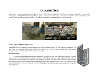
2. US Citizen
32 Sunrise Ave, 973-557-0371
Bloomingdale NJ, 07403 White261@purdue.edu
Education
Purdue University [Fall 2012 – Spring 2016]
Bachelor of Science in Aeronautical & Astronautical Engineering
Minor in Electrical Engineering
GPA: 3.42/4.00
Skills
Programming Languages: C++, Matlab, LabView, Python 2 and 3, ROS (Robotic Operating System)
CAD, CAM, FEA and Manufacturing: CATIA, ANSYS FEA, SolidWorks, GIBBS, G-code, CNC lathe and milling machines, FEMM (Finite Element Method Magnetics)
Electronics Hardware: Arduino, Rabbit Core Module
Other: Open Water Dive Certification, New Jersey Boating Certification, Interest in pursuing Sky Diving License
Work Experience
Millennium Space Systems (El Segundo, CA) [Intern Summer 2015]
Modified a 6 DOF balloon platform to simulate satellite movement and increased carrying capacity and structural stiffness.
Integrated ROS framework across multiple computers to control balloon.
Installed Infrared Motion Capture System (MOCAP) and integrated into ROS.
Built and programmed laser mounted gimbal controlled though ROS to track objects in (MOCAP) volume.
Telemetrics Inc. (Mahwah, NJ) [Intern Summer 2014]
Redesigned components to eliminate 2 hours of installation time on a robot camera trolley.
Led Intern project to create green screen tracking program, focused on tracking algorithm and mechanical design of system.
Redesigned and modified components during production when critical parts from suppliers were manufactured incorrectly.
Tech Products Inc. (Midland Park, NJ) [Part Time 2008 – 2011]
Operating CNC Milling and lathe equipment, CAM using GIBBS, product assembly and testing.
3. LUNABOTICS
Lunabotics is a student run club that competed in the NASA Robotic Mining Competition. The following robot was constructed in 2 semesters for
the competition in May 2016. The challenge of the competition is to autonomously navigate a course of lunar regolith simulant to reach a designated
location where as much regolith as possible is to be mined before returning and dumping it into a designated bin.
Design of Bucket Elevator Excavator
Overview: Since the competition focused on mining the bucket elevator was one of the most important components. The
goal was to mine to a depth of between 30 and 40 cm. The decision for a bucket elevator was made early on after a trade
study comparing it to other methods such as augers and scoops.
Structural Design:
The structure for the bucket elevator was designed in two parts; the outer cage and the inner elevator. The outer
cage mounts to the rest of the robot and supports the actuators to drive the inner elevator into the regolith. The inner elevator
is designed to house the buckets on its outside and the motor and gearbox to drive them within its structure. Both structures
were constructed with square aluminum tube fixed together with sheet metal braces and rivets. This was the quickest
construction method for the team and would allow for a fairly light structure (reducing mass was an important sub-goal in
the competition).
4. Lowering Mechanism:
To bring the bucket elevator down to the depth between 30 and 40 cm the elevator used two electric linear actuators on either side. These
actuators were sized to be powerful enough to dig into the tough regolith and also powerful enough to resist the upward force caused by the bucket
elevator digging.
Rotation Mechanism:
To accommodate the required length of the bucket elevator within the confines of the competition size requirements the entire bucket elevator
needed to be rotated into a horizontal position for the beginning of the competition. Without the rotation mechanism a bucket elevator tall enough
to reach atleast 30 cm digging depth would be above the robot height limit (.75m). However since the length of the robot could be 1.5m rotating the
elevator back was the best option. The rotation mechanism was a simple electric actuator moving the bucket elevator about its rotating mounts.
Results:
The final outcome of the competition was unfortunately not as well as we had hoped. The BP-1 used by NASA was far more difficult to
mine through than the simulant we used to construct out simulation pit. In the end the motor was undersized and unable to dig properly. Taking from
that experience the team is ready with designs to put in a far more powerful motor for the 2017 competition.
Project Website: http://web.ics.purdue.edu/~lunabot/
5. Project Legacy Moon Base
Project Legacy was a senior design project at Purdue University for spring semester 2016 AAE 450. The goal of
the project was to design a moon base to sustain 8 astronauts and to test technologies for the eventual journey to
Mars. The project included all of the construction phases and stages of project technological development and
testing. The following exerts are from my personal involvement in the project.
Design of 20Mg Cargo Lander
Overview: One of the Project requirements was to design a 20 Mg Cargo Lunar Lander. This component was
broken into 3 parts; the Trajectory, the Mass Properties and a 3D Model.
Trajectory:
The trajectory is composed of three phases; the initial circular orbit (4550 km radius), the transfer ellipse, and the constant thrust landing
burn. The Cargo lander begins in the circular orbit having been delivered there by the SLS EUS. The Lander performs an impulsive burn to put it
into the transfer ellipse lowering the perigee to just above the surface. From that perigee the Lander performs a constant deceleration burn until it
reaches the surface. The constant thrust burn is characterized by a two boundary value problem which optimizes the burn time for a given perigee.
The perigee is then altered to optimize the burn time around that. The burn time is proportional to the mass of propellant leading to a mass optimized
trajectory.
Mass Properties:
Since no accurate estimate of Inert Mass fraction can be made the
calculations were made for a range of initial mass and then the inert mass
fraction calculated from final mass and desired payload. The plots were then
generated showing how the allowable Inert Mass Fraction changed based on the
Initial Mass. The Inert mass fraction was then bounded using historical values
(.05 to .11) to create a probable range of the mass of the Lander.
3D Model:
The following 3D model was based on using the average historical Inert
Mass Fraction (.07) for a Hydrolox engine rocket. It was constructed to estimate
the tank sizes and to fit within the frustum of the SLS Cargo Fairing. It was
created in Solidworks and was later used in the final video of the project
6. available online. The Cylinder above the lander is the 20 Mg Habitat module
which is the main cargo for this lander. From left to right it is the Cargo Lander
packaged within the SLS Cargo Fairing, the Lander and Cargo in landing
configuration and finally the Lander with the Cargo removed. The design had to
account for the fact the cargo lander had to change shape to fit within the SLS
Cargo Fairing.
Results:
The resulting design methodology was used twice more to design a scaled down version of the lander, 5 Mg Cargo, and a 10 Mg Cargo
reusable ferrying vehicle that was capable of being launched from the moon’s surface to orbit and then returning to be refueled by ISRU. Both
vehicles used the exact same methodology to be designed as the 20 Mg Cargo Lander.
Other Project Contributions
Moon Base Radiation Shield Design
Moon Base Construction
Moon Base Habitat Module Design
Management of ISRU Resources
Project Video
Project Website: https://engineering.purdue.edu/AAECourses/aae450/2016/spring
Project Video: https://www.youtube.com/watch?v=Yk4tOM3XKFU
7. AAE 535 Design Build Test: Turbopump
The AAE 535 Design Build Test Turbopump project focused on the design and subsequent
manufacturing of the first university made Turbopump. The Turbopump must be capable of
pumping hydrogen peroxide (substituting water for first several test iterations) at a rate of 170
gallons per minute at 1,400 psi. The Turbopump is driven by the hot air supply from Purdue’s
Zucrow Labs. This is a project that has been passed down through several semesters getting
closer to the goal each time.
Manufacturing:
Overview: My focus on the project during spring 2016 was to ensure the manufacturability of all the components based on my previous experiences
in machine shops. Those insights motivated many design changes that drastically reduced cost and time for machining and allowed much of the
manufacturing to shift to on-site machine shops. The design we inherited from previous years was done focusing on mass optimization, which for
rockets is great. Unfortunately, this left the design far too costly to manufacture. The focus for my semester’s design was to optimize for
manufacturing with far less concern for mass (which is irrelevant at this stage since this iteration will never go beyond a test stand). The turbine was
changed from radial inlet to axial to improve flow but to also allow for a simpler inlet and outlet design. The pump side remained largely unchanged
except for some redesign of the flow path for the water outlet. The resulting design is currently being manufactured over summer 2016.