SlideShare a Scribd company logo
Basics of Wireless Networks
➢ Network – a collection of terminals, computers, servers and
components which allows for the easy flow of data and use of
resources among them(in case of wired environment)
➢ Wireless network – Any type of computer network that is
wireless.
Allows us to connect our computer to a network using radio
waves instead of wires.
➢ Wireless network Architecture – Defines the elements of the
wireless network that participate in communication across the
geographically distributed area.
The History and Evolution of Wireless Radio Systems
History of Wireless Radio Systems
• 1867 – Maxwell's predicted existence of EM Waves.
• 1872 - Marlon Loomis was issued a U.S. patent for a crude
type of aerial wireless telegraph .
• 1887 - Heinrich Hertz performed laboratory experiments, that
proved the existence of electromagnetic waves.
• 1890 – Branly developed Coherer (apparatus for detecting
radio waves)
• 1896 – Marconi demonstrated wireless telegraph.
• 1897 – “Birth of radio” by Marconi and he started “Marconi
station” on needles island to communicate with the English
coast.
contd….
• 1898 – Marconi experimented on tuned communication .
Wireless telegraph connection between England & France
established.
• From 1895 to 1901 Marconi experimented with a wireless
telegraph system.
• December 12, 1901 - Marconi sent a message (the signal was
a repetitive letter “s” in Morse code) from Cornwall, England
to Signal Hill, St. John’s, Newfoundland—the first transmission
across the Atlantic Ocean.
• 1902 – First bidirectional communication across Atlantic.
• 1909 – Marconi awarded Nobel prize for physics.
Evolution of wireless radio system
• Early AM wireless system
• First Broadcast
• Modern AM
• Development of FM
• Evolution of Digital Radio
• Cellular telephone concept.
Early AM Wireless Systems
• A typical early wireless transmitter is shown in Figure 1–1.
• The wireless transmitter would emit a signal of either long or short
duration depending on the length of time the telegraph key was closed.
• The transmitted signal was the electromagnetic noise produced by the
spark-gap discharge. This signal propagated through the air to a receiver
located at some distance from the transmitter.
• The inductance & capacitance used to tune the output frequency of the
spark gap.
• Due to the nature of the spark gap emission , maximum output occurs at a
very low frequency.
• At the receiver, the detected signal was interpreted by an operator as
either a dot or a dash depending upon its duration.
• Using Morse code, combinations of dots and dashes stood for various
alphanumeric characters. This early wireless transmission form is now
known as amplitude modulation (AM) and in particular, on-off keying
(OOK).
Limitations
➢ Very low frequency transmitter
➢ Low power & unstable output
➢ Need bigger & high elevated antenna
➢ Modulated signal is very sensitive to noise.
Remedies
These limitations can be overcome by using next
generator wireless transmitter.
The First Broadcast
• 1905 - Reginald Fessenden conducted experiments with
continuous wave (CW) wireless transmissions at Brant Rock,
Massachusetts, using 50-kHz high-frequency alternators built
by General Electric.
• The output of this type of generator was much more stable
than that of a spark-gap or Poulsen transmitter, allowing him
to experiment with a continuous form of amplitude
modulation.
• 1906 – He credited with transmitting the first radio broadcast.
• 1910 - U.S. Navy led a major effort to develop wireless radio
for ship-to-ship and ship-to-shore communications.
• 1920 – (i)Decade of high-frequency or short-wave radio
development.
Contd..
(ii) Marconi’s research on radio wave propagation revealed
that trans-atlantic radio transmission was feasible at frequencies
much higher than that had previously been done.
(iii)vacuum-tube technology had improved to such an extent as
to increase the upper-frequency limit of their operation.
• 1926 – trans-oceanic telephone calls were available via high-
frequency radio transmission.
• 1930 – 1940
Saw more advancement in radio technology with the
invention of television, radar, and vacuum tubes with the ability
to generate “microwaves.”
Modern AM
• Amplitude modulation has been used for low-frequency radio
broadcasting, shortwave broadcasting, low-definition
television video-signal transmission, amateur and CB radio
and various other low-profile services.
• Newer uses of AM include quadrature amplitude modulation
(QAM or n-QAM, where n is a power of 2).
• QAM is a hybrid form of amplitude and phase modulation
(PM) used for high-speed data transmission at RF frequencies.
• QAM is considered a digital modulation technique. Today,
QAM is used extensively by broadband cable and wireless
systems to achieve bandwidth efficiency.
The Development of FM
• 1920s - Major Edwin Armstrong worked on the principles of frequency and
phase modulation
• late 1960s and early 1970s - FM broadcasting became popular.
• technological advances reduced the cost of consumer equipment and
improved the quality of service.
• Many public safety departments were early adopters of FM for their
communications.
• 1983 – AMPS(Advance Mobile Phone System) cellular telephone service,
an FM-based system, was introduced in the United States
• Today FM is used –
- for transmissions in the FM broadcast band
- TV-broadcasting sound transmission
- direct-satellite TV service
- cordless telephones
- every type of business band and mobile radio service.
• FM is capable of much more noise immunity than AM, and is now the
most popular form of analog modulation.
The Evolution of Digital Radio
• 1936 - The first experimental broadband coaxial cable was
tested
• 1941 - the first operational L1 system that could handle 480
telephone calls was installed in Microwave radio relay systems
developed in tandem with broadband coaxial cable systems.
• 1947- The first microwave relay system was installed between
Boston and New York
• 1951 - AT&T’s coast-to-coast microwave radio relay system
was in place by Microwave relay systems which had lower
construction and maintenance costs than coaxial cable .
• By 1970s, AT&T’s microwave relay system carried 70% of its
voice traffic and 95% of its broadband television traffic.
Contd..
• Most of these systems used analog forms of modulation,
although simple digital modulation forms like binary
frequency shift keying (BFSK) existed.
• 1970s and 1980s - microwave digital radio technology and
digital modulation techniques provide increased data rates
over the same radio channel .
• Many of the analog and digital microwave relay systems in use
became backup systems with newly installed fiber-optic
cables.
Contd..
• Many service providers of point-to-point connectivity were
employing microwave and millimeter-wave radio transmission
systems that use the most modern digital modulation
techniques to obtain high data rate links.
• Cellular operators were using economical point-to-point
microwave radio systems to backhaul aggregated bandwidth
signals to a common network interface point from both
remote and not-so-remote cell sites.
• Wireless Internet service providers (WISPs) are using digital
radio equipment designed for the Unlicensed National
Information Infrastructure (U-NII) bands for point-to-point
and point-to-multipoint systems that provide high bit-rate
Internet connections to their customers.
Contd..
• The television broadcasting industry is in the process of
transitioning to a high-definition television (HDTV) standard
for over the-air broadcast that uses a digital transmission
system.
• the oldest analog cellular systems (these systems are in the
process of being phased out) are digital, and all of the newest
wireless LAN, MAN, and PAN technologies use complex digital
modulation schemes.
The cellular telephone concept
• Evolved from earlier mobile radio networks.
• The first mobile radio was used by police
department or other low enforcement
agencies.
• One way mobile radio system operating at
2Mhz – used to page the police cars.
• 1968 – FCC asked for a proposal with high
capacity, efficient mobile phone system.
• AT & T proposed core idea of cellular system.
The development of modern telecommunications Infrastructure
➢ The wireless networks and systems have the basic function of
connecting users to public Switched Telephone
network(PSTN) or the Public Data Network(PDN).
➢ So it is necessary to examine- what these 2 public networks
are ? & How they have evolved?
The Public Switched Telephone Network(PSTN)
To explain the physical infrastructure of the PSTN, it is necessary to
consider the various pathways of communication available through the
system.
Two types of PSTN
(i) Intra-office
(ii) Inter-office
A PSTN Intra-office call through a local exchange
A PSTN inter-office call over an inter-exchange trunk line
➢Signaling System #7
➢ The early PSTN USED “In – band “ signaling to set up
inter-office and long distance telephone calls – This
has many disadvantages.
➢ The system of using a separate facility or channel to
perform the call routing function has developed.
➢ “Out of band “ signaling
➢ Today it is called CCIS(Common Channel Interface
Signaling) or SS#7.
The Network Elements of SS7 System
➢ SS7 system is a packet network that consists of STP & Transmission
facilities linking the STP’s as shown in fig.3
➢ The STP’s are connected to SSP’s at local exchange and interface
with the local exchange switch or mobile switching center in case of
a PLMN(public land mobile network)
➢ SSP’s convert signaling information to SS7 signaling Messages in the
form of data packets that are sent over SS7 network.
➢ STP’s serve as routers.
➢ RCL’s between STP’s provide SS7 network with a degree of
reliability.
➢ SS7 provides 2 forms of services:-
- Circuit related –Setting up & tearing down of circuits
- Non circuit related –Access of information from data bases
maintained by the network.
➢SCP – Acts as interface between SS7 network and various databases
maintained by telephone companies.
➢NOC(Network operation center) is the maintenance center.
➢All PSTN and PLMN’s use SS7 for signaling operations within the
network and between the network and other networks.

More Related Content

Similar to Wireless_Communication_PPT_2-_unit_1.pdf

introdution to analog and digital communication
introdution to analog and digital communicationintrodution to analog and digital communication
introdution to analog and digital communication
Sugeng Widodo
 
cellular communication
cellular communicationcellular communication
cellular communication
jhcid
 
RF VLSI DESIGN-INTRODUCTION.pptx
RF VLSI DESIGN-INTRODUCTION.pptxRF VLSI DESIGN-INTRODUCTION.pptx
RF VLSI DESIGN-INTRODUCTION.pptx
PraveenRaj608598
 
1_Introduction.pptx
1_Introduction.pptx1_Introduction.pptx
1_Introduction.pptx
BashirAhmed396449
 
1g to 5g technologies
1g to 5g technologies1g to 5g technologies
L 1 overview of telecom network
L 1 overview of telecom networkL 1 overview of telecom network
L 1 overview of telecom network
Bala V
 
wireless and mobile communications by ugr
wireless and mobile communications by ugrwireless and mobile communications by ugr
wireless and mobile communications by ugr
ugenderacsegnitc
 
Chapter Two.pdf
Chapter Two.pdfChapter Two.pdf
Chapter Two.pdf
MamushLeta
 
Pert-1-Pengenalan-Jaringan-Nirkabel.pdf
Pert-1-Pengenalan-Jaringan-Nirkabel.pdfPert-1-Pengenalan-Jaringan-Nirkabel.pdf
Pert-1-Pengenalan-Jaringan-Nirkabel.pdf
TaufikIqbalR1
 
Wireless communication
Wireless communicationWireless communication
Wireless communication
Liton Ahmed
 
Data Communication 1
Data Communication 1Data Communication 1
Data Communication 1
admercano101
 
Radio waves presentation
Radio waves presentationRadio waves presentation
Radio waves presentation
04burkem
 
Final ppt wireless
Final ppt wirelessFinal ppt wireless
Final ppt wireless
Prachi Patki
 
Basics of wireless communication
Basics of wireless communicationBasics of wireless communication
Basics of wireless communication
RAVIKIRAN ANANDE
 
Cellular communications
Cellular communicationsCellular communications
Cellular communications
MuhammadAwais662
 
Chap 1&2(history and intro) wireless communication
Chap 1&2(history and intro) wireless communicationChap 1&2(history and intro) wireless communication
Chap 1&2(history and intro) wireless communication
asadkhan1327
 
Wireless Communication & Networking
Wireless Communication & NetworkingWireless Communication & Networking
Wireless Communication & Networking
Mohit Somani
 
Introduction wireless communication network
Introduction wireless communication networkIntroduction wireless communication network
Introduction wireless communication network
Riazul Islam
 
Final wireless communication
Final wireless communicationFinal wireless communication
Final wireless communication
jingyueyu
 
Lecture 2 evolution of mobile cellular
Lecture 2  evolution of mobile cellular Lecture 2  evolution of mobile cellular
Lecture 2 evolution of mobile cellular
Chandra Meena
 

Similar to Wireless_Communication_PPT_2-_unit_1.pdf (20)

introdution to analog and digital communication
introdution to analog and digital communicationintrodution to analog and digital communication
introdution to analog and digital communication
 
cellular communication
cellular communicationcellular communication
cellular communication
 
RF VLSI DESIGN-INTRODUCTION.pptx
RF VLSI DESIGN-INTRODUCTION.pptxRF VLSI DESIGN-INTRODUCTION.pptx
RF VLSI DESIGN-INTRODUCTION.pptx
 
1_Introduction.pptx
1_Introduction.pptx1_Introduction.pptx
1_Introduction.pptx
 
1g to 5g technologies
1g to 5g technologies1g to 5g technologies
1g to 5g technologies
 
L 1 overview of telecom network
L 1 overview of telecom networkL 1 overview of telecom network
L 1 overview of telecom network
 
wireless and mobile communications by ugr
wireless and mobile communications by ugrwireless and mobile communications by ugr
wireless and mobile communications by ugr
 
Chapter Two.pdf
Chapter Two.pdfChapter Two.pdf
Chapter Two.pdf
 
Pert-1-Pengenalan-Jaringan-Nirkabel.pdf
Pert-1-Pengenalan-Jaringan-Nirkabel.pdfPert-1-Pengenalan-Jaringan-Nirkabel.pdf
Pert-1-Pengenalan-Jaringan-Nirkabel.pdf
 
Wireless communication
Wireless communicationWireless communication
Wireless communication
 
Data Communication 1
Data Communication 1Data Communication 1
Data Communication 1
 
Radio waves presentation
Radio waves presentationRadio waves presentation
Radio waves presentation
 
Final ppt wireless
Final ppt wirelessFinal ppt wireless
Final ppt wireless
 
Basics of wireless communication
Basics of wireless communicationBasics of wireless communication
Basics of wireless communication
 
Cellular communications
Cellular communicationsCellular communications
Cellular communications
 
Chap 1&2(history and intro) wireless communication
Chap 1&2(history and intro) wireless communicationChap 1&2(history and intro) wireless communication
Chap 1&2(history and intro) wireless communication
 
Wireless Communication & Networking
Wireless Communication & NetworkingWireless Communication & Networking
Wireless Communication & Networking
 
Introduction wireless communication network
Introduction wireless communication networkIntroduction wireless communication network
Introduction wireless communication network
 
Final wireless communication
Final wireless communicationFinal wireless communication
Final wireless communication
 
Lecture 2 evolution of mobile cellular
Lecture 2  evolution of mobile cellular Lecture 2  evolution of mobile cellular
Lecture 2 evolution of mobile cellular
 

More from ssuser136534

basic_electronic_class_5.pdf
basic_electronic_class_5.pdfbasic_electronic_class_5.pdf
basic_electronic_class_5.pdf
ssuser136534
 
Artificial_Neural_Network.pdf
Artificial_Neural_Network.pdfArtificial_Neural_Network.pdf
Artificial_Neural_Network.pdf
ssuser136534
 
Signals (1).pdf
Signals  (1).pdfSignals  (1).pdf
Signals (1).pdf
ssuser136534
 
typicales-210510062115.pdf
typicales-210510062115.pdftypicales-210510062115.pdf
typicales-210510062115.pdf
ssuser136534
 
Electronics_Devices_class_8.pdf
Electronics_Devices_class_8.pdfElectronics_Devices_class_8.pdf
Electronics_Devices_class_8.pdf
ssuser136534
 
Electronics_Devices_class_8.pdf
Electronics_Devices_class_8.pdfElectronics_Devices_class_8.pdf
Electronics_Devices_class_8.pdf
ssuser136534
 
Wireless_Communication_PPT_4-unit_1.pdf
Wireless_Communication_PPT_4-unit_1.pdfWireless_Communication_PPT_4-unit_1.pdf
Wireless_Communication_PPT_4-unit_1.pdf
ssuser136534
 
Wireless_Communication_UNIT_4.pdf
Wireless_Communication_UNIT_4.pdfWireless_Communication_UNIT_4.pdf
Wireless_Communication_UNIT_4.pdf
ssuser136534
 
Control_Systems_Unit5.pdf
Control_Systems_Unit5.pdfControl_Systems_Unit5.pdf
Control_Systems_Unit5.pdf
ssuser136534
 
Signals_Systems_Unit2_part2.pdf
Signals_Systems_Unit2_part2.pdfSignals_Systems_Unit2_part2.pdf
Signals_Systems_Unit2_part2.pdf
ssuser136534
 
Signals_Systems_Unit3.pdf
Signals_Systems_Unit3.pdfSignals_Systems_Unit3.pdf
Signals_Systems_Unit3.pdf
ssuser136534
 
18EC33_Network_Theory_PPTs.pdf
18EC33_Network_Theory_PPTs.pdf18EC33_Network_Theory_PPTs.pdf
18EC33_Network_Theory_PPTs.pdf
ssuser136534
 
Electronics_Devices_class_10.pdf
Electronics_Devices_class_10.pdfElectronics_Devices_class_10.pdf
Electronics_Devices_class_10.pdf
ssuser136534
 
Electronics_Devices_class_4.pdf
Electronics_Devices_class_4.pdfElectronics_Devices_class_4.pdf
Electronics_Devices_class_4.pdf
ssuser136534
 
Electronics_Devices_class_1.pdf
Electronics_Devices_class_1.pdfElectronics_Devices_class_1.pdf
Electronics_Devices_class_1.pdf
ssuser136534
 
Electronics_Devices_class_13.pdf
Electronics_Devices_class_13.pdfElectronics_Devices_class_13.pdf
Electronics_Devices_class_13.pdf
ssuser136534
 

More from ssuser136534 (16)

basic_electronic_class_5.pdf
basic_electronic_class_5.pdfbasic_electronic_class_5.pdf
basic_electronic_class_5.pdf
 
Artificial_Neural_Network.pdf
Artificial_Neural_Network.pdfArtificial_Neural_Network.pdf
Artificial_Neural_Network.pdf
 
Signals (1).pdf
Signals  (1).pdfSignals  (1).pdf
Signals (1).pdf
 
typicales-210510062115.pdf
typicales-210510062115.pdftypicales-210510062115.pdf
typicales-210510062115.pdf
 
Electronics_Devices_class_8.pdf
Electronics_Devices_class_8.pdfElectronics_Devices_class_8.pdf
Electronics_Devices_class_8.pdf
 
Electronics_Devices_class_8.pdf
Electronics_Devices_class_8.pdfElectronics_Devices_class_8.pdf
Electronics_Devices_class_8.pdf
 
Wireless_Communication_PPT_4-unit_1.pdf
Wireless_Communication_PPT_4-unit_1.pdfWireless_Communication_PPT_4-unit_1.pdf
Wireless_Communication_PPT_4-unit_1.pdf
 
Wireless_Communication_UNIT_4.pdf
Wireless_Communication_UNIT_4.pdfWireless_Communication_UNIT_4.pdf
Wireless_Communication_UNIT_4.pdf
 
Control_Systems_Unit5.pdf
Control_Systems_Unit5.pdfControl_Systems_Unit5.pdf
Control_Systems_Unit5.pdf
 
Signals_Systems_Unit2_part2.pdf
Signals_Systems_Unit2_part2.pdfSignals_Systems_Unit2_part2.pdf
Signals_Systems_Unit2_part2.pdf
 
Signals_Systems_Unit3.pdf
Signals_Systems_Unit3.pdfSignals_Systems_Unit3.pdf
Signals_Systems_Unit3.pdf
 
18EC33_Network_Theory_PPTs.pdf
18EC33_Network_Theory_PPTs.pdf18EC33_Network_Theory_PPTs.pdf
18EC33_Network_Theory_PPTs.pdf
 
Electronics_Devices_class_10.pdf
Electronics_Devices_class_10.pdfElectronics_Devices_class_10.pdf
Electronics_Devices_class_10.pdf
 
Electronics_Devices_class_4.pdf
Electronics_Devices_class_4.pdfElectronics_Devices_class_4.pdf
Electronics_Devices_class_4.pdf
 
Electronics_Devices_class_1.pdf
Electronics_Devices_class_1.pdfElectronics_Devices_class_1.pdf
Electronics_Devices_class_1.pdf
 
Electronics_Devices_class_13.pdf
Electronics_Devices_class_13.pdfElectronics_Devices_class_13.pdf
Electronics_Devices_class_13.pdf
 

Recently uploaded

Presentation of IEEE Slovenia CIS (Computational Intelligence Society) Chapte...
Presentation of IEEE Slovenia CIS (Computational Intelligence Society) Chapte...Presentation of IEEE Slovenia CIS (Computational Intelligence Society) Chapte...
Presentation of IEEE Slovenia CIS (Computational Intelligence Society) Chapte...
University of Maribor
 
ML Based Model for NIDS MSc Updated Presentation.v2.pptx
ML Based Model for NIDS MSc Updated Presentation.v2.pptxML Based Model for NIDS MSc Updated Presentation.v2.pptx
ML Based Model for NIDS MSc Updated Presentation.v2.pptx
JamalHussainArman
 
Technical Drawings introduction to drawing of prisms
Technical Drawings introduction to drawing of prismsTechnical Drawings introduction to drawing of prisms
Technical Drawings introduction to drawing of prisms
heavyhaig
 
Series of visio cisco devices Cisco_Icons.ppt
Series of visio cisco devices Cisco_Icons.pptSeries of visio cisco devices Cisco_Icons.ppt
Series of visio cisco devices Cisco_Icons.ppt
PauloRodrigues104553
 
Manufacturing Process of molasses based distillery ppt.pptx
Manufacturing Process of molasses based distillery ppt.pptxManufacturing Process of molasses based distillery ppt.pptx
Manufacturing Process of molasses based distillery ppt.pptx
Madan Karki
 
Recycled Concrete Aggregate in Construction Part III
Recycled Concrete Aggregate in Construction Part IIIRecycled Concrete Aggregate in Construction Part III
Recycled Concrete Aggregate in Construction Part III
Aditya Rajan Patra
 
Low power architecture of logic gates using adiabatic techniques
Low power architecture of logic gates using adiabatic techniquesLow power architecture of logic gates using adiabatic techniques
Low power architecture of logic gates using adiabatic techniques
nooriasukmaningtyas
 
Harnessing WebAssembly for Real-time Stateless Streaming Pipelines
Harnessing WebAssembly for Real-time Stateless Streaming PipelinesHarnessing WebAssembly for Real-time Stateless Streaming Pipelines
Harnessing WebAssembly for Real-time Stateless Streaming Pipelines
Christina Lin
 
[JPP-1] - (JEE 3.0) - Kinematics 1D - 14th May..pdf
[JPP-1] - (JEE 3.0) - Kinematics 1D - 14th May..pdf[JPP-1] - (JEE 3.0) - Kinematics 1D - 14th May..pdf
[JPP-1] - (JEE 3.0) - Kinematics 1D - 14th May..pdf
awadeshbabu
 
22CYT12-Unit-V-E Waste and its Management.ppt
22CYT12-Unit-V-E Waste and its Management.ppt22CYT12-Unit-V-E Waste and its Management.ppt
22CYT12-Unit-V-E Waste and its Management.ppt
KrishnaveniKrishnara1
 
CHINA’S GEO-ECONOMIC OUTREACH IN CENTRAL ASIAN COUNTRIES AND FUTURE PROSPECT
CHINA’S GEO-ECONOMIC OUTREACH IN CENTRAL ASIAN COUNTRIES AND FUTURE PROSPECTCHINA’S GEO-ECONOMIC OUTREACH IN CENTRAL ASIAN COUNTRIES AND FUTURE PROSPECT
CHINA’S GEO-ECONOMIC OUTREACH IN CENTRAL ASIAN COUNTRIES AND FUTURE PROSPECT
jpsjournal1
 
Embedded machine learning-based road conditions and driving behavior monitoring
Embedded machine learning-based road conditions and driving behavior monitoringEmbedded machine learning-based road conditions and driving behavior monitoring
Embedded machine learning-based road conditions and driving behavior monitoring
IJECEIAES
 
ACRP 4-09 Risk Assessment Method to Support Modification of Airfield Separat...
ACRP 4-09 Risk Assessment Method to Support Modification of Airfield Separat...ACRP 4-09 Risk Assessment Method to Support Modification of Airfield Separat...
ACRP 4-09 Risk Assessment Method to Support Modification of Airfield Separat...
Mukeshwaran Balu
 
Advanced control scheme of doubly fed induction generator for wind turbine us...
Advanced control scheme of doubly fed induction generator for wind turbine us...Advanced control scheme of doubly fed induction generator for wind turbine us...
Advanced control scheme of doubly fed induction generator for wind turbine us...
IJECEIAES
 
KuberTENes Birthday Bash Guadalajara - K8sGPT first impressions
KuberTENes Birthday Bash Guadalajara - K8sGPT first impressionsKuberTENes Birthday Bash Guadalajara - K8sGPT first impressions
KuberTENes Birthday Bash Guadalajara - K8sGPT first impressions
Victor Morales
 
RAT: Retrieval Augmented Thoughts Elicit Context-Aware Reasoning in Long-Hori...
RAT: Retrieval Augmented Thoughts Elicit Context-Aware Reasoning in Long-Hori...RAT: Retrieval Augmented Thoughts Elicit Context-Aware Reasoning in Long-Hori...
RAT: Retrieval Augmented Thoughts Elicit Context-Aware Reasoning in Long-Hori...
thanhdowork
 
DEEP LEARNING FOR SMART GRID INTRUSION DETECTION: A HYBRID CNN-LSTM-BASED MODEL
DEEP LEARNING FOR SMART GRID INTRUSION DETECTION: A HYBRID CNN-LSTM-BASED MODELDEEP LEARNING FOR SMART GRID INTRUSION DETECTION: A HYBRID CNN-LSTM-BASED MODEL
DEEP LEARNING FOR SMART GRID INTRUSION DETECTION: A HYBRID CNN-LSTM-BASED MODEL
gerogepatton
 
132/33KV substation case study Presentation
132/33KV substation case study Presentation132/33KV substation case study Presentation
132/33KV substation case study Presentation
kandramariana6
 
Understanding Inductive Bias in Machine Learning
Understanding Inductive Bias in Machine LearningUnderstanding Inductive Bias in Machine Learning
Understanding Inductive Bias in Machine Learning
SUTEJAS
 
Question paper of renewable energy sources
Question paper of renewable energy sourcesQuestion paper of renewable energy sources
Question paper of renewable energy sources
mahammadsalmanmech
 

Recently uploaded (20)

Presentation of IEEE Slovenia CIS (Computational Intelligence Society) Chapte...
Presentation of IEEE Slovenia CIS (Computational Intelligence Society) Chapte...Presentation of IEEE Slovenia CIS (Computational Intelligence Society) Chapte...
Presentation of IEEE Slovenia CIS (Computational Intelligence Society) Chapte...
 
ML Based Model for NIDS MSc Updated Presentation.v2.pptx
ML Based Model for NIDS MSc Updated Presentation.v2.pptxML Based Model for NIDS MSc Updated Presentation.v2.pptx
ML Based Model for NIDS MSc Updated Presentation.v2.pptx
 
Technical Drawings introduction to drawing of prisms
Technical Drawings introduction to drawing of prismsTechnical Drawings introduction to drawing of prisms
Technical Drawings introduction to drawing of prisms
 
Series of visio cisco devices Cisco_Icons.ppt
Series of visio cisco devices Cisco_Icons.pptSeries of visio cisco devices Cisco_Icons.ppt
Series of visio cisco devices Cisco_Icons.ppt
 
Manufacturing Process of molasses based distillery ppt.pptx
Manufacturing Process of molasses based distillery ppt.pptxManufacturing Process of molasses based distillery ppt.pptx
Manufacturing Process of molasses based distillery ppt.pptx
 
Recycled Concrete Aggregate in Construction Part III
Recycled Concrete Aggregate in Construction Part IIIRecycled Concrete Aggregate in Construction Part III
Recycled Concrete Aggregate in Construction Part III
 
Low power architecture of logic gates using adiabatic techniques
Low power architecture of logic gates using adiabatic techniquesLow power architecture of logic gates using adiabatic techniques
Low power architecture of logic gates using adiabatic techniques
 
Harnessing WebAssembly for Real-time Stateless Streaming Pipelines
Harnessing WebAssembly for Real-time Stateless Streaming PipelinesHarnessing WebAssembly for Real-time Stateless Streaming Pipelines
Harnessing WebAssembly for Real-time Stateless Streaming Pipelines
 
[JPP-1] - (JEE 3.0) - Kinematics 1D - 14th May..pdf
[JPP-1] - (JEE 3.0) - Kinematics 1D - 14th May..pdf[JPP-1] - (JEE 3.0) - Kinematics 1D - 14th May..pdf
[JPP-1] - (JEE 3.0) - Kinematics 1D - 14th May..pdf
 
22CYT12-Unit-V-E Waste and its Management.ppt
22CYT12-Unit-V-E Waste and its Management.ppt22CYT12-Unit-V-E Waste and its Management.ppt
22CYT12-Unit-V-E Waste and its Management.ppt
 
CHINA’S GEO-ECONOMIC OUTREACH IN CENTRAL ASIAN COUNTRIES AND FUTURE PROSPECT
CHINA’S GEO-ECONOMIC OUTREACH IN CENTRAL ASIAN COUNTRIES AND FUTURE PROSPECTCHINA’S GEO-ECONOMIC OUTREACH IN CENTRAL ASIAN COUNTRIES AND FUTURE PROSPECT
CHINA’S GEO-ECONOMIC OUTREACH IN CENTRAL ASIAN COUNTRIES AND FUTURE PROSPECT
 
Embedded machine learning-based road conditions and driving behavior monitoring
Embedded machine learning-based road conditions and driving behavior monitoringEmbedded machine learning-based road conditions and driving behavior monitoring
Embedded machine learning-based road conditions and driving behavior monitoring
 
ACRP 4-09 Risk Assessment Method to Support Modification of Airfield Separat...
ACRP 4-09 Risk Assessment Method to Support Modification of Airfield Separat...ACRP 4-09 Risk Assessment Method to Support Modification of Airfield Separat...
ACRP 4-09 Risk Assessment Method to Support Modification of Airfield Separat...
 
Advanced control scheme of doubly fed induction generator for wind turbine us...
Advanced control scheme of doubly fed induction generator for wind turbine us...Advanced control scheme of doubly fed induction generator for wind turbine us...
Advanced control scheme of doubly fed induction generator for wind turbine us...
 
KuberTENes Birthday Bash Guadalajara - K8sGPT first impressions
KuberTENes Birthday Bash Guadalajara - K8sGPT first impressionsKuberTENes Birthday Bash Guadalajara - K8sGPT first impressions
KuberTENes Birthday Bash Guadalajara - K8sGPT first impressions
 
RAT: Retrieval Augmented Thoughts Elicit Context-Aware Reasoning in Long-Hori...
RAT: Retrieval Augmented Thoughts Elicit Context-Aware Reasoning in Long-Hori...RAT: Retrieval Augmented Thoughts Elicit Context-Aware Reasoning in Long-Hori...
RAT: Retrieval Augmented Thoughts Elicit Context-Aware Reasoning in Long-Hori...
 
DEEP LEARNING FOR SMART GRID INTRUSION DETECTION: A HYBRID CNN-LSTM-BASED MODEL
DEEP LEARNING FOR SMART GRID INTRUSION DETECTION: A HYBRID CNN-LSTM-BASED MODELDEEP LEARNING FOR SMART GRID INTRUSION DETECTION: A HYBRID CNN-LSTM-BASED MODEL
DEEP LEARNING FOR SMART GRID INTRUSION DETECTION: A HYBRID CNN-LSTM-BASED MODEL
 
132/33KV substation case study Presentation
132/33KV substation case study Presentation132/33KV substation case study Presentation
132/33KV substation case study Presentation
 
Understanding Inductive Bias in Machine Learning
Understanding Inductive Bias in Machine LearningUnderstanding Inductive Bias in Machine Learning
Understanding Inductive Bias in Machine Learning
 
Question paper of renewable energy sources
Question paper of renewable energy sourcesQuestion paper of renewable energy sources
Question paper of renewable energy sources
 

Wireless_Communication_PPT_2-_unit_1.pdf

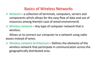
  • 1. Basics of Wireless Networks ➢ Network – a collection of terminals, computers, servers and components which allows for the easy flow of data and use of resources among them(in case of wired environment) ➢ Wireless network – Any type of computer network that is wireless. Allows us to connect our computer to a network using radio waves instead of wires. ➢ Wireless network Architecture – Defines the elements of the wireless network that participate in communication across the geographically distributed area.
  • 2. The History and Evolution of Wireless Radio Systems History of Wireless Radio Systems • 1867 – Maxwell's predicted existence of EM Waves. • 1872 - Marlon Loomis was issued a U.S. patent for a crude type of aerial wireless telegraph . • 1887 - Heinrich Hertz performed laboratory experiments, that proved the existence of electromagnetic waves. • 1890 – Branly developed Coherer (apparatus for detecting radio waves) • 1896 – Marconi demonstrated wireless telegraph. • 1897 – “Birth of radio” by Marconi and he started “Marconi station” on needles island to communicate with the English coast.
  • 3. contd…. • 1898 – Marconi experimented on tuned communication . Wireless telegraph connection between England & France established. • From 1895 to 1901 Marconi experimented with a wireless telegraph system. • December 12, 1901 - Marconi sent a message (the signal was a repetitive letter “s” in Morse code) from Cornwall, England to Signal Hill, St. John’s, Newfoundland—the first transmission across the Atlantic Ocean. • 1902 – First bidirectional communication across Atlantic. • 1909 – Marconi awarded Nobel prize for physics.
  • 4. Evolution of wireless radio system • Early AM wireless system • First Broadcast • Modern AM • Development of FM • Evolution of Digital Radio • Cellular telephone concept.
  • 5. Early AM Wireless Systems • A typical early wireless transmitter is shown in Figure 1–1. • The wireless transmitter would emit a signal of either long or short duration depending on the length of time the telegraph key was closed. • The transmitted signal was the electromagnetic noise produced by the spark-gap discharge. This signal propagated through the air to a receiver located at some distance from the transmitter. • The inductance & capacitance used to tune the output frequency of the spark gap. • Due to the nature of the spark gap emission , maximum output occurs at a very low frequency. • At the receiver, the detected signal was interpreted by an operator as either a dot or a dash depending upon its duration. • Using Morse code, combinations of dots and dashes stood for various alphanumeric characters. This early wireless transmission form is now known as amplitude modulation (AM) and in particular, on-off keying (OOK).
  • 6.
  • 7. Limitations ➢ Very low frequency transmitter ➢ Low power & unstable output ➢ Need bigger & high elevated antenna ➢ Modulated signal is very sensitive to noise. Remedies These limitations can be overcome by using next generator wireless transmitter.
  • 8. The First Broadcast • 1905 - Reginald Fessenden conducted experiments with continuous wave (CW) wireless transmissions at Brant Rock, Massachusetts, using 50-kHz high-frequency alternators built by General Electric. • The output of this type of generator was much more stable than that of a spark-gap or Poulsen transmitter, allowing him to experiment with a continuous form of amplitude modulation. • 1906 – He credited with transmitting the first radio broadcast. • 1910 - U.S. Navy led a major effort to develop wireless radio for ship-to-ship and ship-to-shore communications. • 1920 – (i)Decade of high-frequency or short-wave radio development.
  • 9. Contd.. (ii) Marconi’s research on radio wave propagation revealed that trans-atlantic radio transmission was feasible at frequencies much higher than that had previously been done. (iii)vacuum-tube technology had improved to such an extent as to increase the upper-frequency limit of their operation. • 1926 – trans-oceanic telephone calls were available via high- frequency radio transmission. • 1930 – 1940 Saw more advancement in radio technology with the invention of television, radar, and vacuum tubes with the ability to generate “microwaves.”
  • 10. Modern AM • Amplitude modulation has been used for low-frequency radio broadcasting, shortwave broadcasting, low-definition television video-signal transmission, amateur and CB radio and various other low-profile services. • Newer uses of AM include quadrature amplitude modulation (QAM or n-QAM, where n is a power of 2). • QAM is a hybrid form of amplitude and phase modulation (PM) used for high-speed data transmission at RF frequencies. • QAM is considered a digital modulation technique. Today, QAM is used extensively by broadband cable and wireless systems to achieve bandwidth efficiency.
  • 11. The Development of FM • 1920s - Major Edwin Armstrong worked on the principles of frequency and phase modulation • late 1960s and early 1970s - FM broadcasting became popular. • technological advances reduced the cost of consumer equipment and improved the quality of service. • Many public safety departments were early adopters of FM for their communications. • 1983 – AMPS(Advance Mobile Phone System) cellular telephone service, an FM-based system, was introduced in the United States • Today FM is used – - for transmissions in the FM broadcast band - TV-broadcasting sound transmission - direct-satellite TV service - cordless telephones - every type of business band and mobile radio service. • FM is capable of much more noise immunity than AM, and is now the most popular form of analog modulation.
  • 12. The Evolution of Digital Radio • 1936 - The first experimental broadband coaxial cable was tested • 1941 - the first operational L1 system that could handle 480 telephone calls was installed in Microwave radio relay systems developed in tandem with broadband coaxial cable systems. • 1947- The first microwave relay system was installed between Boston and New York • 1951 - AT&T’s coast-to-coast microwave radio relay system was in place by Microwave relay systems which had lower construction and maintenance costs than coaxial cable . • By 1970s, AT&T’s microwave relay system carried 70% of its voice traffic and 95% of its broadband television traffic.
  • 13. Contd.. • Most of these systems used analog forms of modulation, although simple digital modulation forms like binary frequency shift keying (BFSK) existed. • 1970s and 1980s - microwave digital radio technology and digital modulation techniques provide increased data rates over the same radio channel . • Many of the analog and digital microwave relay systems in use became backup systems with newly installed fiber-optic cables.
  • 14. Contd.. • Many service providers of point-to-point connectivity were employing microwave and millimeter-wave radio transmission systems that use the most modern digital modulation techniques to obtain high data rate links. • Cellular operators were using economical point-to-point microwave radio systems to backhaul aggregated bandwidth signals to a common network interface point from both remote and not-so-remote cell sites. • Wireless Internet service providers (WISPs) are using digital radio equipment designed for the Unlicensed National Information Infrastructure (U-NII) bands for point-to-point and point-to-multipoint systems that provide high bit-rate Internet connections to their customers.
  • 15. Contd.. • The television broadcasting industry is in the process of transitioning to a high-definition television (HDTV) standard for over the-air broadcast that uses a digital transmission system. • the oldest analog cellular systems (these systems are in the process of being phased out) are digital, and all of the newest wireless LAN, MAN, and PAN technologies use complex digital modulation schemes.
  • 16. The cellular telephone concept • Evolved from earlier mobile radio networks. • The first mobile radio was used by police department or other low enforcement agencies. • One way mobile radio system operating at 2Mhz – used to page the police cars. • 1968 – FCC asked for a proposal with high capacity, efficient mobile phone system. • AT & T proposed core idea of cellular system.
  • 17. The development of modern telecommunications Infrastructure ➢ The wireless networks and systems have the basic function of connecting users to public Switched Telephone network(PSTN) or the Public Data Network(PDN). ➢ So it is necessary to examine- what these 2 public networks are ? & How they have evolved? The Public Switched Telephone Network(PSTN) To explain the physical infrastructure of the PSTN, it is necessary to consider the various pathways of communication available through the system. Two types of PSTN (i) Intra-office (ii) Inter-office
  • 18. A PSTN Intra-office call through a local exchange
  • 19. A PSTN inter-office call over an inter-exchange trunk line
  • 20. ➢Signaling System #7 ➢ The early PSTN USED “In – band “ signaling to set up inter-office and long distance telephone calls – This has many disadvantages. ➢ The system of using a separate facility or channel to perform the call routing function has developed. ➢ “Out of band “ signaling ➢ Today it is called CCIS(Common Channel Interface Signaling) or SS#7.
  • 21. The Network Elements of SS7 System
  • 22.
  • 23. ➢ SS7 system is a packet network that consists of STP & Transmission facilities linking the STP’s as shown in fig.3 ➢ The STP’s are connected to SSP’s at local exchange and interface with the local exchange switch or mobile switching center in case of a PLMN(public land mobile network) ➢ SSP’s convert signaling information to SS7 signaling Messages in the form of data packets that are sent over SS7 network. ➢ STP’s serve as routers. ➢ RCL’s between STP’s provide SS7 network with a degree of reliability. ➢ SS7 provides 2 forms of services:- - Circuit related –Setting up & tearing down of circuits - Non circuit related –Access of information from data bases maintained by the network. ➢SCP – Acts as interface between SS7 network and various databases maintained by telephone companies. ➢NOC(Network operation center) is the maintenance center. ➢All PSTN and PLMN’s use SS7 for signaling operations within the network and between the network and other networks.