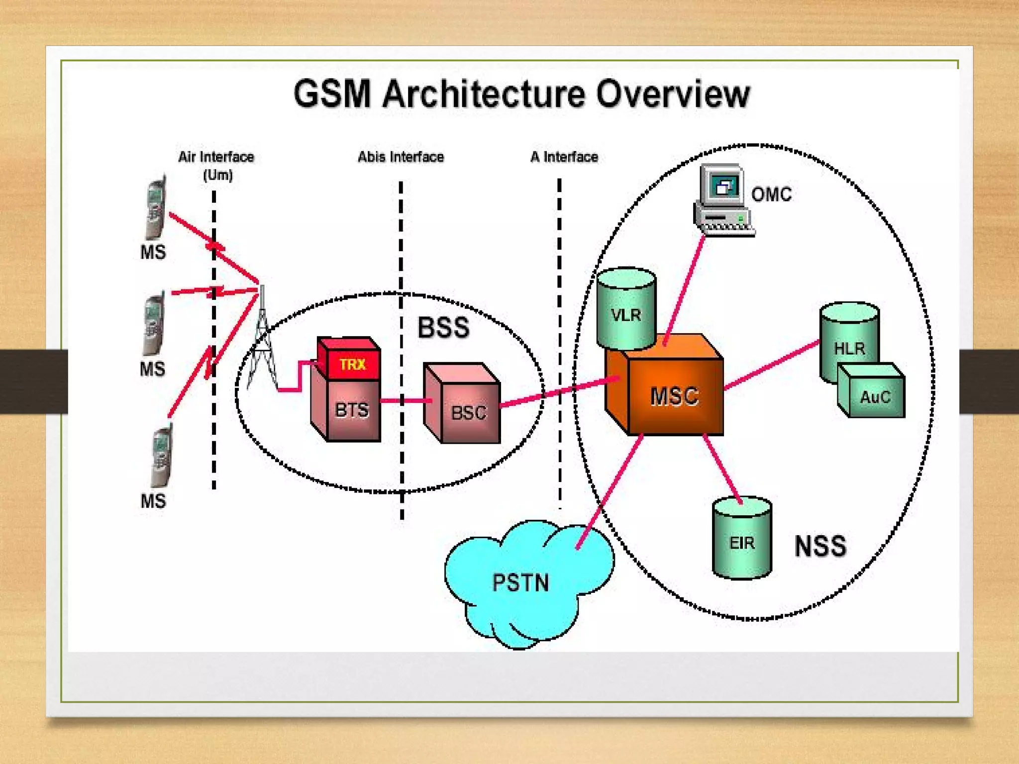
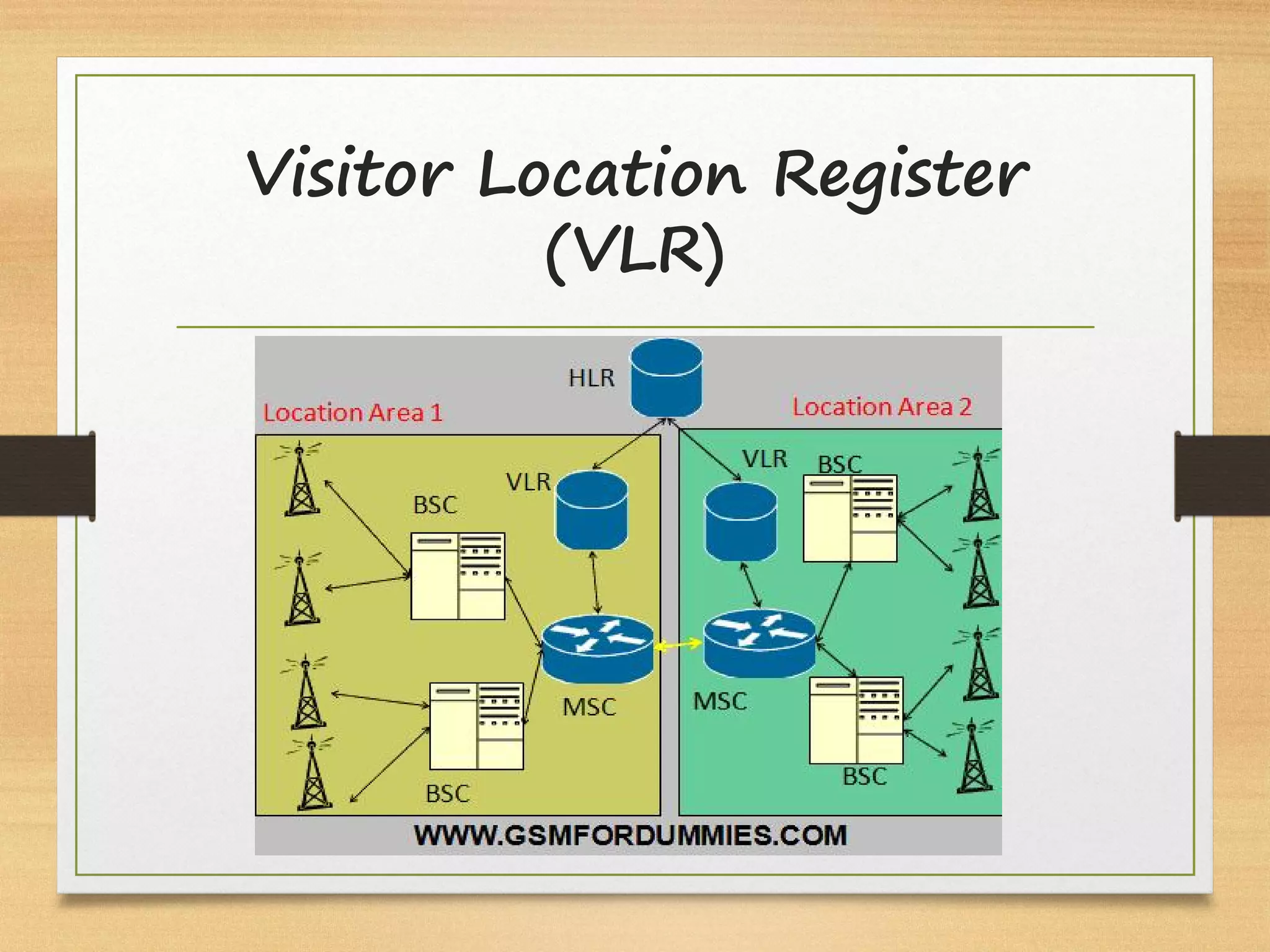
CELLULAR COMMUNICATION
SYSTEM
(Lecture 1)
Dr. Lory Liza D. Bulay-og, PECE
MAIN COMPONENT IN CELLULAR
COMMUNICATION SYSTEM
Evolution to cellular
networks – communication anytime,
anywhere
• radio communication was invented by Nikola Tesla and
Guglielmo Marconi: in 1893, Nikola Tesla made the first
public demonstration of wireless (radio) telegraphy;
Guglielmo Marconi conducted long ditance (over see)
telegraphy 1897
• in 1940 the first walkie-talkie was used by the US
military
• in 1947, John Bardeen and Walter Brattain from
AT&T’s Bell Labs invented the transistor (semiconductor
device used to amplify and switch electronic signals)
• AT&T introduced commercial radio comm.: car phone –
two way radio link to the local phone network
• in 1979 the first commercial cellular phone service was
launched by the Nordic Mobile Telephone (in Finland,
Sweden, Norway, Denmark).
Mobile?
• The term “mobile” has historically been
used to classify all radio terminal that could
be moved during operation.
Ø More recently,
use “mobile” to describe a radio
terminal that is attached to a high
speed mobile platform
e.g., a cellular telephone in a fast
moving vehicle
Ø use “portable” to describes a radio terminal
that can be hand-held and used by someone at
walking speed
e.g., a walkie-talkie or cordless telephone
inside a home
Current Wireless Systems
• Cellular systems
• Wireless LANs
• Satellite Systems
• Paging Systems
• Bluetooth
• Ultrawideband Radios
• Zigbee Radios
Wireless Systems: Range Comparison
Satellite
Links
SW
Radio
MW
Radio
FM
Radio
Mobile
Telephony
WLANs
Blueooth
1,000 Km
100 Km
10 Km
1 Km
100 m
10 m
1 m
What is Cellular
Communication System
• Cellular communication is designed to
provide communications between two
moving units, or between one
mobile unit and one stationary phone or
land unit (PSTN).
A. Pre-Cellular
• The most successful application of wireless
networking has been the cellular telephone
system.
ü The roots of this system began in 1915, when
wireless voice transmission between New York
and San Francisco was first established.
• 1946: First public mobile telephone service
was introduced in 25 cities across the
United States.
ü The equipment was expensive at $2,000
ü More than the price of a typical new car (at
that time).
Cellular systems generations
• These initial systems used a single
central transmitter to cover an entire
metropolitan area.
ü High-powered transmitter & Large tower
ü Inefficient!
ü FM push-to-talk
• 1976: (30 yrs after the introduction of
the service in 1946)
• The mobile units weighed about 10
kilograms and put out a steady 20-25
watts.
• The central transmitters that
communicate with the mobile units
broadcast 200 to 250 watts.
• The central station could reliably
communicate with the mobile units up
to a radius of approximately 25 miles
(50 km).
ü Beyond that, up to a radius of 60 to 100
miles, the signal was too weak for consistent
service, but strong enough to interfere with
any other mobile radio system.
ü As a result, the central transmitters had to
be at least 100 miles apart, leaving a 50
mile blank space between them.
• So a customer could use the sporadic
and unreliable service only within the
confines of one area.
B. 1G Cellular
- voice-oriented systems based on analog
technology; ex.: Advanced Mobile Phone Systems
(AMPS) and cordless systems.
• During the 50’s and 60’s researchers at AT&T
Bell Laboratories developed the cellular concept.
ü 1968: AT&T proposed the concept to the FCC
ü Cellular systems exploit the fact that the power of a
transmitted signal falls off with distance.
ü Thus, two users can operate on the same frequency at
spatially-separate locations with minimal interference
between them.
Cellular systems generations
• Japan had the world’s first commercially
available cellular phone system.
ü Nippon Telegraph and Telephone (NTT) created
a cellular test system for Tokyo in 1975, with
the result coming to market in 1979.
• The first trial in America of a complete,
working cellular system was held in Chicago
in the late 1970’s.
• 1983: Advanced Mobile Phone System
(AMPS)
ü First US cellular telephone system
ü Deployed in 1983 by Ameritech in Chacago, IL.
ü Worked well. (FM, FDMA)
ü Its satisfactory performance lowered the
demand for a better system, allowing Europe
to take the lead by creating a digital cellular
system first.
C. 2G Cellular
• The first-generation (1G) systems introduced in
the 1980s were characterized by analog speech
transmission.
• The second generation (2G) of cellular systems,
first deployed in the early 1990’s, were based
on digital communications.
• The shift from analog to digital was driven by
its higher capacity and the improved cost, speed,
and power efficiency of digital hardware.
Cellular systems generations
• 1991: US Digital Cellular (USDC – IS-54 > IS-
136)
ü Three times capacity of AMPS because digital
modulation, speech coding, and TDMA
• While second generation cellular systems
initially provided mainly voice services,
these systems gradually evolved to
support data services such as email,
Internet access, and short messaging.
GSM
• supports SMSs and
user data at rates
only up to 9.6 kb/s.
Ø Security features
including (for
example) the
encryption of data
and signaling
messages on the path
between the mobile
phone and the BS.
Ø Subscriber identity
module (SIM)
IS-95B (cdmaOne)
• provides data rates in
the range of 64 to
115 kb/s in
increments of 8 kb/s
over a 1.25 MHz
channel.
Ø Each cell uses a
carrier with a
bandwidth of
1.25MHz, which is
divided into 64 data
and signalling
channels by the use of
orthogonal CDMA
Two important 2G systems
• Unfortunately, the great market
potential for cellular phones led to a
proliferation of (incompatible) second
generation cellular
• As a result of the standard proliferation,
many cellular phones are forced to be
multi-mode.
2G Standard Proliferation
Major Mobile Radio
Standards in North
America
Major Mobile Radio
Standards in Europe
Major Mobile Radio
Standards in Japan
GSM Enhancement
Want to deliver data as well as voice.
A. 2.5G: General Packet Radio Service
(GPRS)
ü Provide connectivity to IP networks
(Internet).
ü Each slot can handle up to 20 kb/s. Each
user may be allocated up to 8 slots
ü Data rates up to about 160 kb/s per user
are possible.
ü A single time slot may be shared by multiple
users for transferring packet mode data.
B. 2.75G: Enhanced Data Rates for GSM
Evolution (EDGE)
ü Support IP-based services in GSM at rates up to
384 kb/s
ü Originally this acronym stood for Enhanced Data
rates for GSM Evolution, but now it translates into
Enhanced Data rates for Global Evolution, as the
EDGE idea can also be used in systems other than
GSM [Korhonen, 2003]
ü Higher modulation efficiency
ü Only requires a software upgrade to base stations
ü EDGE is popular in North America, where the
allocation of carrier frequencies has made it hard for
GSM operators to upgrade to UMTS.
GSM Enhancement
D. 3G
• Studies started even before the earliest 2G systems arrived on the market.
• International Mobile Telecommunications-2000 (IMT-2000)
ü A subgroup of the International Telecommunication Union (ITU)
ü Published a set of performance requirements of 3G (for both packet-switched and
circuit-switched data):
§ A minimum data rate of 144 Kbps in the vehicular environment
§ A minimum data rate of 384 Kbps in the pedestrian environment
§ A minimum data rate of 2 Mbps in the fixed indoor and picocell environment
• There are several wireless standards and systems that qualify as third
generation (3G) systems.
ü UMTS
ü CDMA2000
ü HSPA
ü HSPA+
E. 4G (LTE)
Cellular systems generations
COMPONENTS IN
CELLULAR
COMMUNICATION SYSTEM
3 main components:
• Mobile Station (MS) – ME, SIM
• Base Station Subsystem (BSS) –
BTS, RBS, BSC
• Network and Switching
Subsystem (NSS) – MSC, VLR,
HLR,
Mobile Station (MS)
• MS is the physical equipment used by a
subscriber
• It comprises two parts:
• The Mobile Equipment (ME)
• Subscriber Identity Module (SIM)
Mobile Equipment (ME)
• ME provides the radio and processing needed to
access the GSM network, plus a man machine
interface MMI to enable the user to access
services.
Mobile Equipment (ME)
ME Function
• Radio transceiver and signal processing
• Radio related operations: power control;
timing advance; discontinuous transmission
(DTX); slow frequency hopping (SFH).
• Call handling
• man-machine interface, display, keypad,
speech transducers.
• interfaces to external equipment e.g. laptops
/ palmtops
Subscriber Identity Module
(SIM)
• Provides personal mobility - user can have
access to subscribed services irrespective of a
specific terminal.
• Contains the International Mobile Subscriber
Identity (IMSI) used to identify the subscriber to
the system, a secret key for authentication, and
other information.
• The SIM card may be protected against
unauthorized use by a password or personal
identity number.
SIM
Function of SIM card
• SIM is a smart card which plugs into the mobile
equipment and contains information about the
mobile subscriber.
• Carries all the subscriber specific information
used by an MS.
• Major functions are to identify the current user
of an MS and to take part in security and
confidentiality procedures.
• Stores recent location data and may also store
personal information for the user such as
abbreviated dialing codes (telephone directory).
 
Specific functions include:
• Permanent storage of a subscriber’s
International Mobile Subscriber Identity (IMSI)
and Authentication key (Ki)
• Semi permanent storage of system information
e.g. current Location Area Identity (LAI),
encryption key Kc and lists of preferred /
forbidden GSM networks
• Semi permanent storage of user data, ‘telephone
directory’, short messages
• Participation in mobility procedures e.g. user
authentication, generation of ciphering key,
instigation of location updates.
The SIM contains several
pieces of information:
  International Module Subscriber Identity (IMSI)
– This number identifies the mobile subscriber.
It is only transmitted over the air during
initialisation.
 Temporary Mobile Subscriber Identity (TMSI) –
This number identifies the subscriber, it is
periodically changed by the system management
to protect the subscriber from being identified
by someone attempting to monitor the radio
interface.
The SIM contains several
pieces of information:
 Location Area Identity (LAI) – Identifies the
current location of the subscriber .
 Subscriber Authentication Key (Ki) – This is
used to authenticate the SIM card.
 Mobile Station International Services Digital
Network (MSISDN) – This is the telephone
number of the mobile. It is comprised of a
country code, a national a subscriber number.
Base Station Subsystem
(BSS)
• BSS is the section of a traditional cellular
telephone network which is responsible for
handling traffic and signaling between a mobile
phone and the NSS.
• The BSS performs all the radio-related
functions.
• The BSS is comprised of the following functional
units:
• Base Station Controller (BSC)
• Base Transceiver Station (BTS)
• BSS communicate to Mobile Station (MS) using
Air Interface
Base Station Subsystem
(BSS)
• Function of BSS
• transcoding of speech channels,
• allocation of radio channels to mobile
phones, 
• paging, 
• transmission and reception over the air
interface 
• and many other tasks related to the radio
network.
• BTS + BSC = BSS.
Base Station Subsystem
(BSS)
Base Station Subsystem
(BSS)
Base Station Subsystem
(BSS)
Base Station Subsystem
(BSS)
• BTS provides physical connection between MS to
network using Air Interface (Um)
• Main function of BTS is for maintaining the Um
interface and minimizing the transmission
problem (Um very sensitive for disturbance)
• Using Abis interface for connection between BTS
and BSC
Base Transceiver Station
(BTS)
Base Transceiver Station
(BTS)
Base Transceiver Station
(BTS)
• A BTS usually placed on center of
the cell
• Its transmitting power defines size
of the cell
• Each BTS has between 1 to 16
transceiver depending on density
of the user in the cell
• Each BTS serve in a single cell
Base Transceiver Station
(BTS)
Base Transceiver Station
(BTS)
 The site controller stations that function
depends on the directions from the MSC.
 Using voice channels - VC (or trafic channel TC)
and control channels – CC as radio channels
communications in each cell
 Supervise the call, monitoring the quality of the
speech and also the measurement of the
strength of the voice signal.
 Send and receive voice signals and data signals
to/from users.
 Interface between users equipment UE and
switching systems MCS
Base Transceiver Station
(BTS)
• The BTS is the Mobile Station's access point to
the network.
• It is responsible for carrying out radio
communications between the network and the
Mobile Station’s.
• It handles speech encoding, encryption,
m u l t i p l e x i n g ( T D M A ) , a n d
modulation/demodulation of the radio signals.
• It is also capable of frequency hopping (changing
carrier frequency while communicating)
• One BTS usually covers a single 120 degree
sector of an area.
Base Transceiver Station
(BTS)
Base Station Controller
(BSC)
• The BSC controls multiple BTS.
• It handles allocation of
- radio channels,
- frequency administration,
- power and signal measurements from
the MS,
- Handovers from one BTS to another (if
both BTSs are controlled by the same
BSC).
Base Station Controller
(BSC)
• A BSC my be collocated
with a BTS or it may be
geographically separate.
• It may even be collocated
with the Mobile Switching
Center (MSC).
Base Station Controller
(BSC)
Base Station Controller
(BSC)
GSM BTS Type
Network & Switching
Subsystem (NSS)
• Mobile Switching Center (MSC)
• Home Location Register (HLR)
• Visitor Location Register (VLR)
• Equipment Identify Register (EIR)
• Authentication Centre (AuC)
• Gateway Mobile Switching Center
(GMSC)
• SMS Gateway (SMS-G)
Mobile Switching Center (MSC)
• The MSC is the heart of the GSM
network.
• From technical perspective MSC is just
an ordinary Integrated Services Digital
Network (ISDN) exchange
• One MSC can handles multiple BSCs and
also interfaces with other MSC's (Using
E-Interface).
• It also handles inter-BSC handoffs as
well as coordinates with other MSC's for
inter-MSC handoffs.
Mobile Switching Center (MSC)
• MSC performs the telephony switching
functions of the system.
• Controls calls to and from other
telephony and data systems, such as the
Public Switched Telephone Network
(PSTN) and Public Land Mobile Network
(PLMN).
Mobile Switching Center (MSC)
• Difference between a MSC and an
exchange in a fixed network, MSC
has to take into account the impact
of the allocation of radio resources
and the mobile nature of the
subscribers and has to perform in
addition, at least the following
procedures:
• required for location registration
• procedures required for handover
Mobile Switching Center (MSC)
• MSC can be connected to only one VLR
or more VLR. Therefore, all mobile
stations that move around under base
stations connected to the MSC are
always managed by the same VLR.
• MSC would communicate typically with
one EIR. While it is possible for an MSC
to communicate to multiple EIRs, this is
highly unlikely since the EIR provides a
centralized and geographic independent
function.
Ericsson Mobile Switching
Center Server (MSC-S)
The Mobile Switching Center Server (MSC-S)
provides control of high-capacity switching in
mobile circuit core networks
The Elements Connected to
The MSC
The MSC connects to the following
elements:
a. The Home Location Register (HLR)
b. The Visitor Location Register (VLR)
c. Equipment Identify Register (EIR)
d. Authentication Centre (AuC)
e. Gateway Mobile Switching Center
(GMSC)
f. SMS Gateway (SMS-G)
Home location register
(HLR)
• HLR is a central database that contains
details of each mobile phone subscriber
that is authorized to use the GSM core
network.
• The HLRs store details of every SIM
card  i s s u e d by t he m obi le phone
operator.
• Each SIM has a unique identifier called
an IMSI which is the primary key to
each HLR record.
Visitor Location Register (VLR)
• When the mobile user visits a PCS network other than
the home system, a temporary record for the mobile user
is created in the visitor location register (VLR) of the
visited system.
• The VLR temporarily stores subscription information
for the visiting subscribers so that the corresponding
MSC can provide service.
• In other words, the VLR is the "other" location register
used to retrieve information for handling calls to or
from a visiting mobile user.
Home Location Register
(HLR)
• Examples of other data stored in the :
• GSM services that the subscriber has
requested or been given.
• GPRS settings to allow the subscriber to
access packet services.
• C u r r e nt l o c a t i o n o f s u b s c r i b e r ( V L R
and serving GPRS support node/SGSN).
• Call divert settings applicable for each
associated MSISDN.
Responsibilities of the HLR
include:
• management of service profiles
• mapping of subscriber identities (MISDN, IMSI)
• supplementary service control and profile
updates
• execution of supplementary service logic e.g.
incoming calls barred.
• passing subscription records to VLR
• directly receives and processes 
MAP transactions and messages from elements
in the GSM network, for example, the location
update messages received as mobile phones roam
around.
Visitor Location Register
(VLR)
• VLR is a database as same as HLR that contains
all subscriber information data for call handling
and mobility management
• VLR provide dynamic data management (HLR
static data management)
• The VLR keeps track of all subscribers roaming
in the VLR service area.
• In GSM system the VLR is integrated with the
MSC
Visitor Location Register
(VLR)
• VLR contains:
• Selective information function from the HLR
• IMSI (the subscriber's identity number).
• Authentication data.
• MSISDN (the subscriber's phone number).
• GSM services that the subscriber is allowed
to access.
• access point (GPRS) subscribed.
• The HLR address of the subscriber.
Function of the VLR include:
• Executing supplementary service programs
(outgoing calls barred)
• Initiating authentication and ciphering
• Initiating paging
• Mapping of various identities (MSISDN, IMSI,
TMSI, MSRN)
• Passing location information to HLR
Function of the VLR include:
• To inform the HLR when subscriber has arrived
in the area covered by the VLR.
• To track where the subscriber when idle mode.
• To allow or disallow which services the
subscriber may use.
• To allocate roaming numbers during the
processing of incoming calls.
• To purge the subscriber record if becomes
inactive whilst in the area and deletes the
subscriber's data after some period and informs
the HLR
• To delete the subscriber record when a
Visitor Location Register
(VLR)
Equipment Identity Register
(EIR) 
• The EIR is a database that keeps tracks of
handsets on the network using the IMEI.
• The EIR was introduced to identify, track and
bar such equipment from being used in the
network
• There is only one EIR per network.
• Composed of three lists.
• The White List
• The Gray List
• The Black List 
Equipment Identity Register
(EIR)
Authentication Centre
(AuC)
• AUC is always integrated with HLR for the
purpose of the authentication.
• The Subscriber Authentication Key (Ki) is
allocated to the subscriber, together with
the IMSI. The Ki is stored in the AUC and
used to provide the triplets, same Ki is also
stored in the SIM.
• AUC stores the following information for
each subscriber
• The IMSI number,
• The individual authentication key Ki
• A version of A3 and A8 algorithm.
Authentication Centre
(AuC)
In AUC following steps are used to produce one
triplet:
1. A non- predictable random number, RAND,
is produced
2. RAND & Ki are used to calculate the Signed
Response (SRES) and the Ciphering Key (Kc)
3. RAND, SRES and Kc are delivered together to
HLR as one triplet.
HLR delivers these triplets to MSC/VLR on request
in such a way that VLR always has at least
one triplet.
Gateway Mobile Switching
Center (GMSC)
• There is another important type of MSC,
called a Gateway Mobile Switching
Center (GMSC).
• The GMSC functions as a gateway
between two networks.
• If a mobile subscriber wants to place a
call to a regular land line, then the call
would have to go through a GMSC in
order to switch to the Public Switched
T e l e p h o n e N e t w o r k ( P S T N ) .
Gateway Mobile Switching
Center (GMSC)
SMS Gateway (SMS-G)
• The SMS GMSC (SMS gateway MSC) is a
gateway MSC that can also receive short
messages.
• The gateway MSC is a mobile network’s
point of contact with other networks.

cellularcommsystem1.pdf

  • 1.
  • 2.
    MAIN COMPONENT INCELLULAR COMMUNICATION SYSTEM
  • 3.
    Evolution to cellular networks– communication anytime, anywhere • radio communication was invented by Nikola Tesla and Guglielmo Marconi: in 1893, Nikola Tesla made the first public demonstration of wireless (radio) telegraphy; Guglielmo Marconi conducted long ditance (over see) telegraphy 1897 • in 1940 the first walkie-talkie was used by the US military • in 1947, John Bardeen and Walter Brattain from AT&T’s Bell Labs invented the transistor (semiconductor device used to amplify and switch electronic signals) • AT&T introduced commercial radio comm.: car phone – two way radio link to the local phone network • in 1979 the first commercial cellular phone service was launched by the Nordic Mobile Telephone (in Finland, Sweden, Norway, Denmark).
  • 5.
    Mobile? • The term“mobile” has historically been used to classify all radio terminal that could be moved during operation. Ø More recently, use “mobile” to describe a radio terminal that is attached to a high speed mobile platform e.g., a cellular telephone in a fast moving vehicle Ø use “portable” to describes a radio terminal that can be hand-held and used by someone at walking speed e.g., a walkie-talkie or cordless telephone inside a home
  • 6.
    Current Wireless Systems •Cellular systems • Wireless LANs • Satellite Systems • Paging Systems • Bluetooth • Ultrawideband Radios • Zigbee Radios
  • 7.
    Wireless Systems: RangeComparison Satellite Links SW Radio MW Radio FM Radio Mobile Telephony WLANs Blueooth 1,000 Km 100 Km 10 Km 1 Km 100 m 10 m 1 m
  • 8.
    What is Cellular CommunicationSystem • Cellular communication is designed to provide communications between two moving units, or between one mobile unit and one stationary phone or land unit (PSTN).
  • 9.
    A. Pre-Cellular • Themost successful application of wireless networking has been the cellular telephone system. ü The roots of this system began in 1915, when wireless voice transmission between New York and San Francisco was first established. • 1946: First public mobile telephone service was introduced in 25 cities across the United States. ü The equipment was expensive at $2,000 ü More than the price of a typical new car (at that time). Cellular systems generations
  • 10.
    • These initialsystems used a single central transmitter to cover an entire metropolitan area. ü High-powered transmitter & Large tower ü Inefficient! ü FM push-to-talk • 1976: (30 yrs after the introduction of the service in 1946) • The mobile units weighed about 10 kilograms and put out a steady 20-25 watts. • The central transmitters that communicate with the mobile units broadcast 200 to 250 watts.
  • 11.
    • The centralstation could reliably communicate with the mobile units up to a radius of approximately 25 miles (50 km). ü Beyond that, up to a radius of 60 to 100 miles, the signal was too weak for consistent service, but strong enough to interfere with any other mobile radio system. ü As a result, the central transmitters had to be at least 100 miles apart, leaving a 50 mile blank space between them. • So a customer could use the sporadic and unreliable service only within the confines of one area.
  • 12.
    B. 1G Cellular -voice-oriented systems based on analog technology; ex.: Advanced Mobile Phone Systems (AMPS) and cordless systems. • During the 50’s and 60’s researchers at AT&T Bell Laboratories developed the cellular concept. ü 1968: AT&T proposed the concept to the FCC ü Cellular systems exploit the fact that the power of a transmitted signal falls off with distance. ü Thus, two users can operate on the same frequency at spatially-separate locations with minimal interference between them. Cellular systems generations
  • 13.
    • Japan hadthe world’s first commercially available cellular phone system. ü Nippon Telegraph and Telephone (NTT) created a cellular test system for Tokyo in 1975, with the result coming to market in 1979. • The first trial in America of a complete, working cellular system was held in Chicago in the late 1970’s. • 1983: Advanced Mobile Phone System (AMPS) ü First US cellular telephone system ü Deployed in 1983 by Ameritech in Chacago, IL. ü Worked well. (FM, FDMA) ü Its satisfactory performance lowered the demand for a better system, allowing Europe to take the lead by creating a digital cellular system first.
  • 14.
    C. 2G Cellular •The first-generation (1G) systems introduced in the 1980s were characterized by analog speech transmission. • The second generation (2G) of cellular systems, first deployed in the early 1990’s, were based on digital communications. • The shift from analog to digital was driven by its higher capacity and the improved cost, speed, and power efficiency of digital hardware. Cellular systems generations
  • 15.
    • 1991: USDigital Cellular (USDC – IS-54 > IS- 136) ü Three times capacity of AMPS because digital modulation, speech coding, and TDMA • While second generation cellular systems initially provided mainly voice services, these systems gradually evolved to support data services such as email, Internet access, and short messaging.
  • 16.
    GSM • supports SMSsand user data at rates only up to 9.6 kb/s. Ø Security features including (for example) the encryption of data and signaling messages on the path between the mobile phone and the BS. Ø Subscriber identity module (SIM) IS-95B (cdmaOne) • provides data rates in the range of 64 to 115 kb/s in increments of 8 kb/s over a 1.25 MHz channel. Ø Each cell uses a carrier with a bandwidth of 1.25MHz, which is divided into 64 data and signalling channels by the use of orthogonal CDMA Two important 2G systems
  • 17.
    • Unfortunately, thegreat market potential for cellular phones led to a proliferation of (incompatible) second generation cellular • As a result of the standard proliferation, many cellular phones are forced to be multi-mode. 2G Standard Proliferation
  • 18.
  • 19.
  • 20.
  • 21.
    GSM Enhancement Want todeliver data as well as voice. A. 2.5G: General Packet Radio Service (GPRS) ü Provide connectivity to IP networks (Internet). ü Each slot can handle up to 20 kb/s. Each user may be allocated up to 8 slots ü Data rates up to about 160 kb/s per user are possible. ü A single time slot may be shared by multiple users for transferring packet mode data.
  • 22.
    B. 2.75G: EnhancedData Rates for GSM Evolution (EDGE) ü Support IP-based services in GSM at rates up to 384 kb/s ü Originally this acronym stood for Enhanced Data rates for GSM Evolution, but now it translates into Enhanced Data rates for Global Evolution, as the EDGE idea can also be used in systems other than GSM [Korhonen, 2003] ü Higher modulation efficiency ü Only requires a software upgrade to base stations ü EDGE is popular in North America, where the allocation of carrier frequencies has made it hard for GSM operators to upgrade to UMTS. GSM Enhancement
  • 23.
    D. 3G • Studiesstarted even before the earliest 2G systems arrived on the market. • International Mobile Telecommunications-2000 (IMT-2000) ü A subgroup of the International Telecommunication Union (ITU) ü Published a set of performance requirements of 3G (for both packet-switched and circuit-switched data): § A minimum data rate of 144 Kbps in the vehicular environment § A minimum data rate of 384 Kbps in the pedestrian environment § A minimum data rate of 2 Mbps in the fixed indoor and picocell environment • There are several wireless standards and systems that qualify as third generation (3G) systems. ü UMTS ü CDMA2000 ü HSPA ü HSPA+ E. 4G (LTE) Cellular systems generations
  • 24.
    COMPONENTS IN CELLULAR COMMUNICATION SYSTEM 3main components: • Mobile Station (MS) – ME, SIM • Base Station Subsystem (BSS) – BTS, RBS, BSC • Network and Switching Subsystem (NSS) – MSC, VLR, HLR,
  • 26.
    Mobile Station (MS) •MS is the physical equipment used by a subscriber • It comprises two parts: • The Mobile Equipment (ME) • Subscriber Identity Module (SIM)
  • 27.
    Mobile Equipment (ME) •ME provides the radio and processing needed to access the GSM network, plus a man machine interface MMI to enable the user to access services.
  • 28.
  • 29.
    ME Function • Radiotransceiver and signal processing • Radio related operations: power control; timing advance; discontinuous transmission (DTX); slow frequency hopping (SFH). • Call handling • man-machine interface, display, keypad, speech transducers. • interfaces to external equipment e.g. laptops / palmtops
  • 30.
    Subscriber Identity Module (SIM) •Provides personal mobility - user can have access to subscribed services irrespective of a specific terminal. • Contains the International Mobile Subscriber Identity (IMSI) used to identify the subscriber to the system, a secret key for authentication, and other information. • The SIM card may be protected against unauthorized use by a password or personal identity number. SIM
  • 31.
    Function of SIMcard • SIM is a smart card which plugs into the mobile equipment and contains information about the mobile subscriber. • Carries all the subscriber specific information used by an MS. • Major functions are to identify the current user of an MS and to take part in security and confidentiality procedures. • Stores recent location data and may also store personal information for the user such as abbreviated dialing codes (telephone directory).  
  • 32.
    Specific functions include: •Permanent storage of a subscriber’s International Mobile Subscriber Identity (IMSI) and Authentication key (Ki) • Semi permanent storage of system information e.g. current Location Area Identity (LAI), encryption key Kc and lists of preferred / forbidden GSM networks • Semi permanent storage of user data, ‘telephone directory’, short messages • Participation in mobility procedures e.g. user authentication, generation of ciphering key, instigation of location updates.
  • 33.
    The SIM containsseveral pieces of information:   International Module Subscriber Identity (IMSI) – This number identifies the mobile subscriber. It is only transmitted over the air during initialisation.  Temporary Mobile Subscriber Identity (TMSI) – This number identifies the subscriber, it is periodically changed by the system management to protect the subscriber from being identified by someone attempting to monitor the radio interface.
  • 34.
    The SIM containsseveral pieces of information:  Location Area Identity (LAI) – Identifies the current location of the subscriber .  Subscriber Authentication Key (Ki) – This is used to authenticate the SIM card.  Mobile Station International Services Digital Network (MSISDN) – This is the telephone number of the mobile. It is comprised of a country code, a national a subscriber number.
  • 35.
    Base Station Subsystem (BSS) •BSS is the section of a traditional cellular telephone network which is responsible for handling traffic and signaling between a mobile phone and the NSS. • The BSS performs all the radio-related functions. • The BSS is comprised of the following functional units: • Base Station Controller (BSC) • Base Transceiver Station (BTS) • BSS communicate to Mobile Station (MS) using Air Interface
  • 36.
    Base Station Subsystem (BSS) •Function of BSS • transcoding of speech channels, • allocation of radio channels to mobile phones,  • paging,  • transmission and reception over the air interface  • and many other tasks related to the radio network. • BTS + BSC = BSS.
  • 37.
  • 38.
  • 39.
  • 40.
  • 41.
    • BTS providesphysical connection between MS to network using Air Interface (Um) • Main function of BTS is for maintaining the Um interface and minimizing the transmission problem (Um very sensitive for disturbance) • Using Abis interface for connection between BTS and BSC Base Transceiver Station (BTS)
  • 42.
  • 43.
    Base Transceiver Station (BTS) •A BTS usually placed on center of the cell • Its transmitting power defines size of the cell • Each BTS has between 1 to 16 transceiver depending on density of the user in the cell • Each BTS serve in a single cell
  • 44.
  • 45.
    Base Transceiver Station (BTS) The site controller stations that function depends on the directions from the MSC.  Using voice channels - VC (or trafic channel TC) and control channels – CC as radio channels communications in each cell  Supervise the call, monitoring the quality of the speech and also the measurement of the strength of the voice signal.  Send and receive voice signals and data signals to/from users.  Interface between users equipment UE and switching systems MCS
  • 46.
    Base Transceiver Station (BTS) •The BTS is the Mobile Station's access point to the network. • It is responsible for carrying out radio communications between the network and the Mobile Station’s. • It handles speech encoding, encryption, m u l t i p l e x i n g ( T D M A ) , a n d modulation/demodulation of the radio signals. • It is also capable of frequency hopping (changing carrier frequency while communicating) • One BTS usually covers a single 120 degree sector of an area.
  • 47.
  • 48.
    Base Station Controller (BSC) •The BSC controls multiple BTS. • It handles allocation of - radio channels, - frequency administration, - power and signal measurements from the MS, - Handovers from one BTS to another (if both BTSs are controlled by the same BSC).
  • 49.
    Base Station Controller (BSC) •A BSC my be collocated with a BTS or it may be geographically separate. • It may even be collocated with the Mobile Switching Center (MSC).
  • 50.
  • 51.
  • 52.
  • 53.
    Network & Switching Subsystem(NSS) • Mobile Switching Center (MSC) • Home Location Register (HLR) • Visitor Location Register (VLR) • Equipment Identify Register (EIR) • Authentication Centre (AuC) • Gateway Mobile Switching Center (GMSC) • SMS Gateway (SMS-G)
  • 54.
    Mobile Switching Center(MSC) • The MSC is the heart of the GSM network. • From technical perspective MSC is just an ordinary Integrated Services Digital Network (ISDN) exchange • One MSC can handles multiple BSCs and also interfaces with other MSC's (Using E-Interface). • It also handles inter-BSC handoffs as well as coordinates with other MSC's for inter-MSC handoffs.
  • 55.
  • 56.
  • 57.
    Mobile Switching Center(MSC) • MSC performs the telephony switching functions of the system. • Controls calls to and from other telephony and data systems, such as the Public Switched Telephone Network (PSTN) and Public Land Mobile Network (PLMN).
  • 58.
    Mobile Switching Center(MSC) • Difference between a MSC and an exchange in a fixed network, MSC has to take into account the impact of the allocation of radio resources and the mobile nature of the subscribers and has to perform in addition, at least the following procedures: • required for location registration • procedures required for handover
  • 59.
    Mobile Switching Center(MSC) • MSC can be connected to only one VLR or more VLR. Therefore, all mobile stations that move around under base stations connected to the MSC are always managed by the same VLR. • MSC would communicate typically with one EIR. While it is possible for an MSC to communicate to multiple EIRs, this is highly unlikely since the EIR provides a centralized and geographic independent function.
  • 60.
    Ericsson Mobile Switching CenterServer (MSC-S) The Mobile Switching Center Server (MSC-S) provides control of high-capacity switching in mobile circuit core networks
  • 61.
    The Elements Connectedto The MSC The MSC connects to the following elements: a. The Home Location Register (HLR) b. The Visitor Location Register (VLR) c. Equipment Identify Register (EIR) d. Authentication Centre (AuC) e. Gateway Mobile Switching Center (GMSC) f. SMS Gateway (SMS-G)
  • 62.
    Home location register (HLR) •HLR is a central database that contains details of each mobile phone subscriber that is authorized to use the GSM core network. • The HLRs store details of every SIM card  i s s u e d by t he m obi le phone operator. • Each SIM has a unique identifier called an IMSI which is the primary key to each HLR record.
  • 63.
    Visitor Location Register(VLR) • When the mobile user visits a PCS network other than the home system, a temporary record for the mobile user is created in the visitor location register (VLR) of the visited system. • The VLR temporarily stores subscription information for the visiting subscribers so that the corresponding MSC can provide service. • In other words, the VLR is the "other" location register used to retrieve information for handling calls to or from a visiting mobile user.
  • 64.
    Home Location Register (HLR) •Examples of other data stored in the : • GSM services that the subscriber has requested or been given. • GPRS settings to allow the subscriber to access packet services. • C u r r e nt l o c a t i o n o f s u b s c r i b e r ( V L R and serving GPRS support node/SGSN). • Call divert settings applicable for each associated MSISDN.
  • 65.
    Responsibilities of theHLR include: • management of service profiles • mapping of subscriber identities (MISDN, IMSI) • supplementary service control and profile updates • execution of supplementary service logic e.g. incoming calls barred. • passing subscription records to VLR • directly receives and processes  MAP transactions and messages from elements in the GSM network, for example, the location update messages received as mobile phones roam around.
  • 66.
    Visitor Location Register (VLR) •VLR is a database as same as HLR that contains all subscriber information data for call handling and mobility management • VLR provide dynamic data management (HLR static data management) • The VLR keeps track of all subscribers roaming in the VLR service area. • In GSM system the VLR is integrated with the MSC
  • 67.
    Visitor Location Register (VLR) •VLR contains: • Selective information function from the HLR • IMSI (the subscriber's identity number). • Authentication data. • MSISDN (the subscriber's phone number). • GSM services that the subscriber is allowed to access. • access point (GPRS) subscribed. • The HLR address of the subscriber.
  • 68.
    Function of theVLR include: • Executing supplementary service programs (outgoing calls barred) • Initiating authentication and ciphering • Initiating paging • Mapping of various identities (MSISDN, IMSI, TMSI, MSRN) • Passing location information to HLR
  • 69.
    Function of theVLR include: • To inform the HLR when subscriber has arrived in the area covered by the VLR. • To track where the subscriber when idle mode. • To allow or disallow which services the subscriber may use. • To allocate roaming numbers during the processing of incoming calls. • To purge the subscriber record if becomes inactive whilst in the area and deletes the subscriber's data after some period and informs the HLR • To delete the subscriber record when a
  • 70.
  • 71.
    Equipment Identity Register (EIR)  •The EIR is a database that keeps tracks of handsets on the network using the IMEI. • The EIR was introduced to identify, track and bar such equipment from being used in the network • There is only one EIR per network. • Composed of three lists. • The White List • The Gray List • The Black List 
  • 72.
  • 73.
    Authentication Centre (AuC) • AUCis always integrated with HLR for the purpose of the authentication. • The Subscriber Authentication Key (Ki) is allocated to the subscriber, together with the IMSI. The Ki is stored in the AUC and used to provide the triplets, same Ki is also stored in the SIM. • AUC stores the following information for each subscriber • The IMSI number, • The individual authentication key Ki • A version of A3 and A8 algorithm.
  • 74.
    Authentication Centre (AuC) In AUCfollowing steps are used to produce one triplet: 1. A non- predictable random number, RAND, is produced 2. RAND & Ki are used to calculate the Signed Response (SRES) and the Ciphering Key (Kc) 3. RAND, SRES and Kc are delivered together to HLR as one triplet. HLR delivers these triplets to MSC/VLR on request in such a way that VLR always has at least one triplet.
  • 75.
    Gateway Mobile Switching Center(GMSC) • There is another important type of MSC, called a Gateway Mobile Switching Center (GMSC). • The GMSC functions as a gateway between two networks. • If a mobile subscriber wants to place a call to a regular land line, then the call would have to go through a GMSC in order to switch to the Public Switched T e l e p h o n e N e t w o r k ( P S T N ) .
  • 76.
  • 77.
    SMS Gateway (SMS-G) •The SMS GMSC (SMS gateway MSC) is a gateway MSC that can also receive short messages. • The gateway MSC is a mobile network’s point of contact with other networks.