Download to read offline
![International Research Journal of Engineering and Technology (IRJET) e-ISSN: 2395 -0056
Volume: 04 Issue: 03 | Mar -2017 www.irjet.net p-ISSN: 2395-0072
© 2017, IRJET | Impact Factor value: 5.181 | ISO 9001:2008 Certified Journal | Page 86
4 Selects command register when
low; and data register when
high
Register
Select
5 Low to write to the register;
High to read from the register
Read/write
6 Sends data to data pins when a
high to low pulse is given
Enable
7
8-bit data pins
DB0
8 DB1
9 DB2
10 DB3
11 DB4
12 DB5
13 DB6
14 DB7
15 Backlight VCC (5V) Led+
16 Backlight Ground (0V) Led-
5. GSM Module:
This is a plug and plays GSM modem which is used to send
SMS, initiate and receive calls and to perform different GSM
operations by controlling it via simple AT commands given
by using microcontrollers and computers.SIM900 moduleis
widely used for all its operationswhichare usedalongwitha
standard RS232 interface which can be used to easily
interface the modem to microcontrollers and computers.
6. RFID reader and RFID tag:
A RFID reader is a device that gives the connection between
the tag data and the enterprise system software that
requires the information. It is commonly known as an
interrogator. The reader interacts with tags that are within
its field of operation, performing any number of tasks
including filtering (searching for tags that meet certain
criteria), simple continuous inventorying, writing (or
encoding) to selected tags, etc.
A RFID tag is made up of an integrated circuit (calledanICor
chip) attached to an antenna which hasbeenprinted, etched,
stamped or vapor-deposited onto a mount which is often a
paper substrate or Poly Ethylene Terephthalate (PET). The
combo of chip and antenna, known as an inlay, is then
converted or sandwiched between a printed label and its
adhesive backing or inserted into a more durable structure.
7. CONCLUSIONS:
Wireless e-passport system uses smart card technology
which gives a clear vision about the benefits of using
smart card technology as this system avoids forgery
and thus increases the security. This decreases the
burden of documentation and thereby reduces the time
consumption. The use of smart card technology makes
the system centralized and thus improves the security.
The security of the system can be further be enhanced
by adding biometric information such as palm scan,
fingerprints, iris scan, digital signature and other active
validation in the passport system. This project finally
look as shown below:
REFERENCES
[1] G. Matthew Ezovski, Steve E. Watkins, ―The
Electronic Passport and the Future of Government-
Issued RFID-Based Identification‖ 2007 IEEE
International Conference on RFID Gaylord Texan
Resort, Grapevine, TX, USA March 26-28, 2007](https://image.slidesharecdn.com/irjet-v4i322-171216110123/75/Wireless-e-passport-using-smart-card-technology-3-2048.jpg)
![International Research Journal of Engineering and Technology (IRJET) e-ISSN: 2395 -0056
Volume: 04 Issue: 03 | Mar -2017 www.irjet.net p-ISSN: 2395-0072
© 2017, IRJET | Impact Factor value: 5.181 | ISO 9001:2008 Certified Journal | Page 87
[2] Piotr Porwik, "The Biometric Passport: The Technical
RequirementsandPossibilitiesofUsing",Biometricsand
Kansei Engineering, International Conference - ICBAKE
on 2009, pp. 65
[3] Marci Meingast, Jennifer King, and Deirdre K.
Mulligan,“Security and Privacy Risks ofEmbeddedRFID
in Everyday Things: the e-Passport and Beyond,"
Journal of Communications, vol.2,no.7,pp.36-48,2007.
[4] Dr. Albert B. Jeng, Elizabeth Hsu, And Chia Hung Lin
Sponsor: "Should and How CC be used to evaluate RFID
based Passports‖, National Communications
Commission, Available:
https://www.commoncriteriaportal.org/iccc/9iccc/pdf
/C2404.pdf](https://image.slidesharecdn.com/irjet-v4i322-171216110123/75/Wireless-e-passport-using-smart-card-technology-4-2048.jpg)

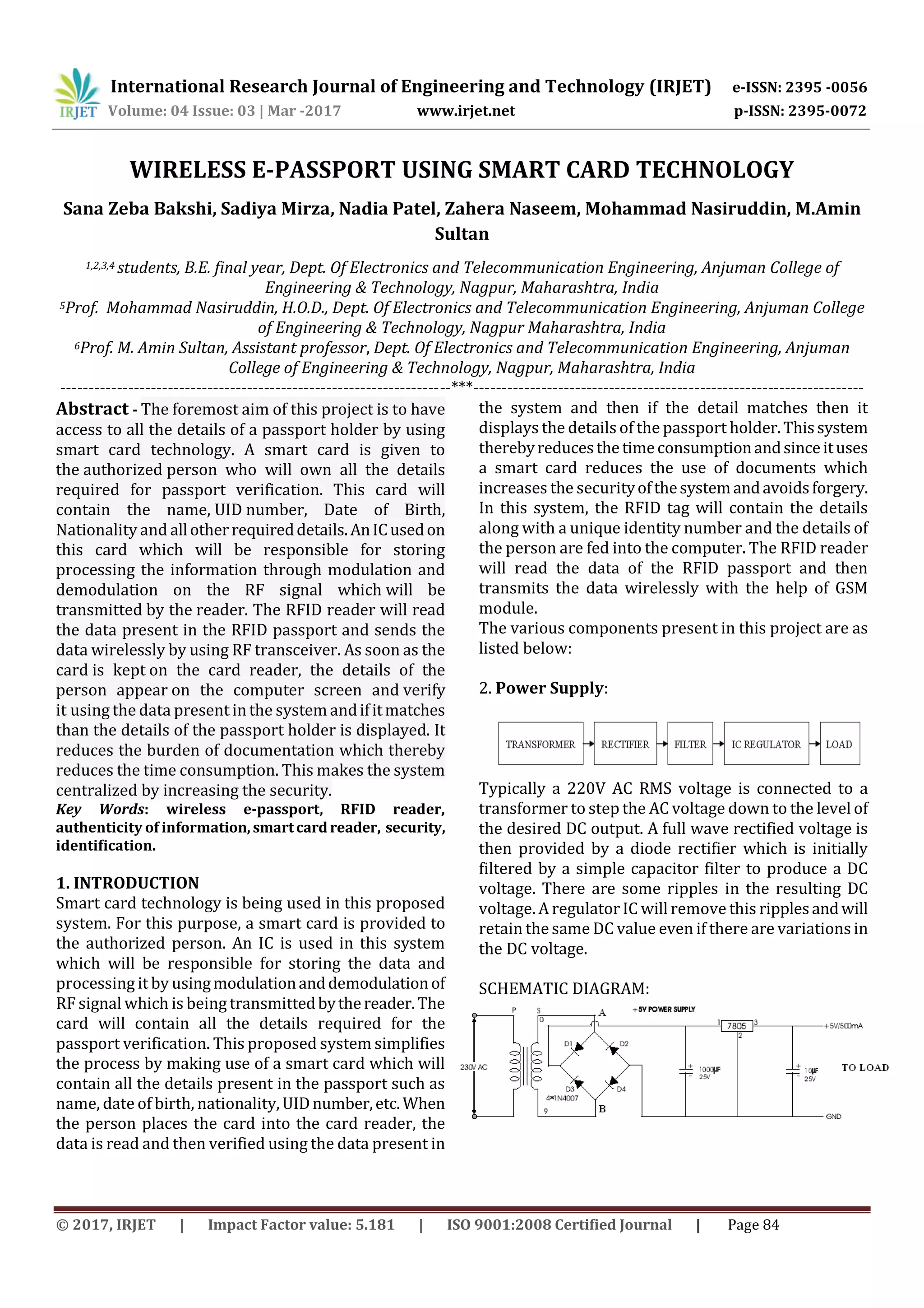
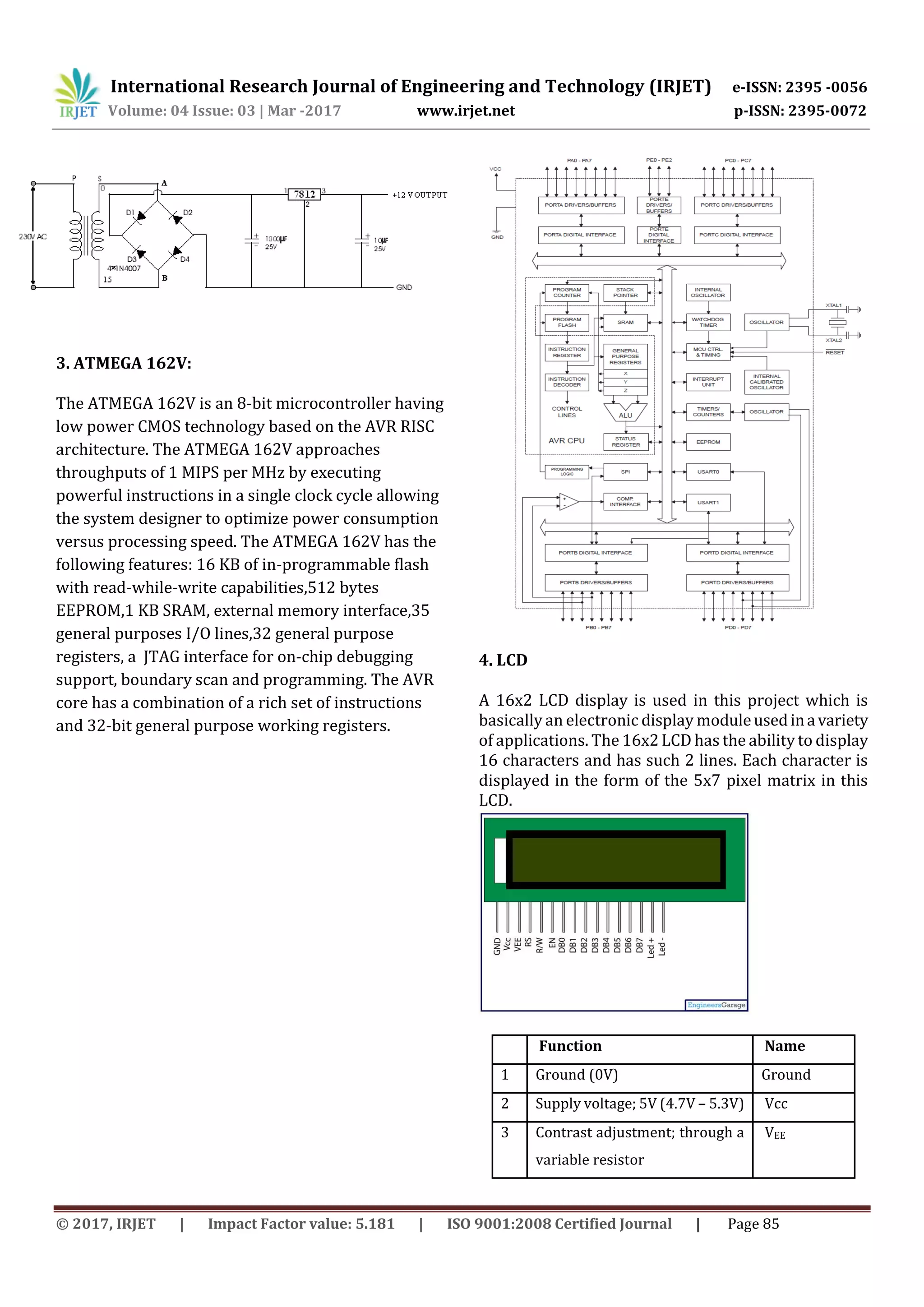
This document describes a proposed wireless e-passport system that uses smart card technology. A smart card containing personal details like name, date of birth, nationality, and UID number is given to the passport holder. When the card is placed near an RFID reader, the details are wirelessly transmitted to a computer system. The system aims to simplify verification and increase security by reducing documentation and preventing forgery. It contains components like a microcontroller, LCD display, GSM module, RFID reader and tag. The smart card technology allows for centralized storage of passport information, faster verification times, and increased security over traditional passports.