Download to read offline


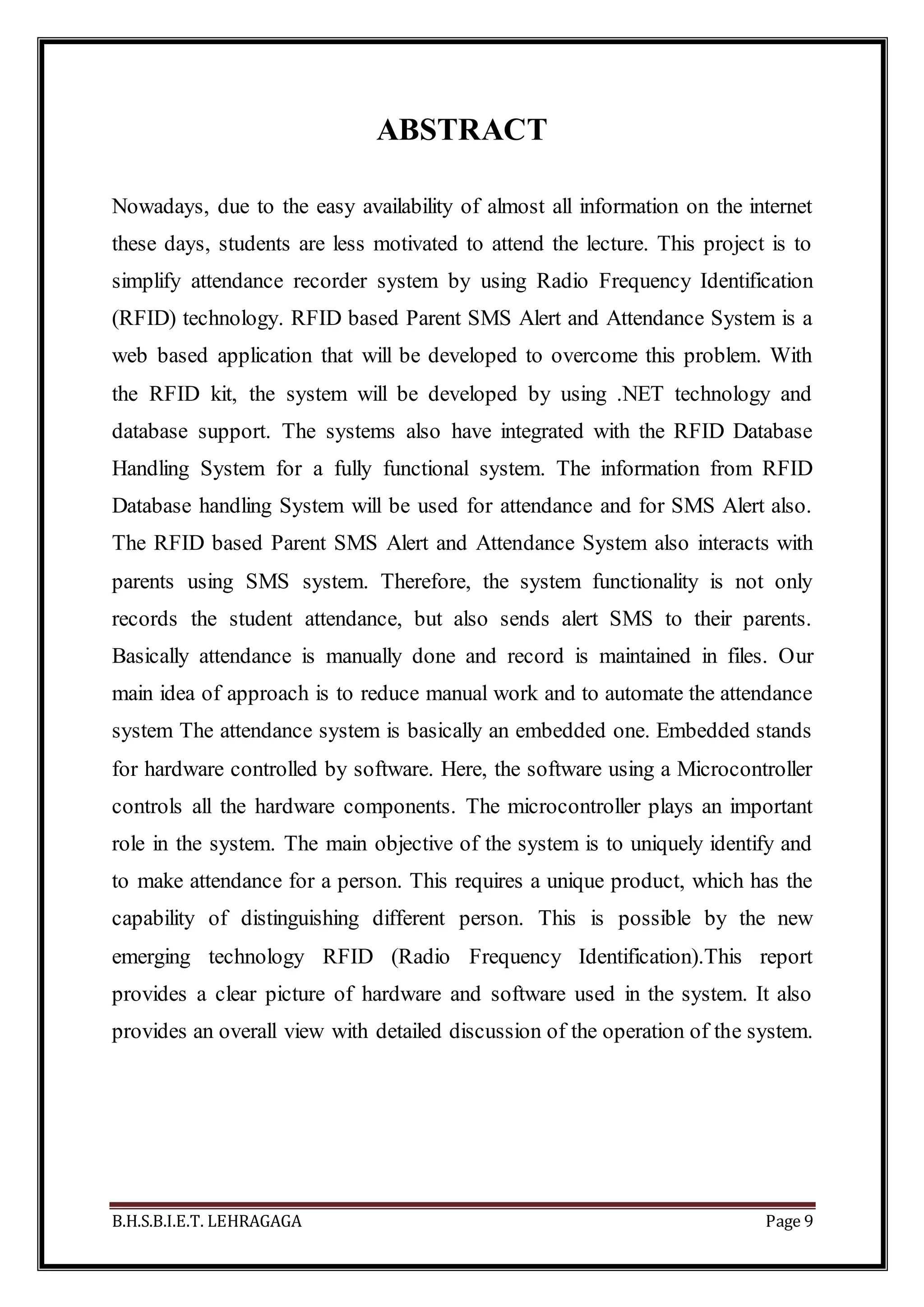
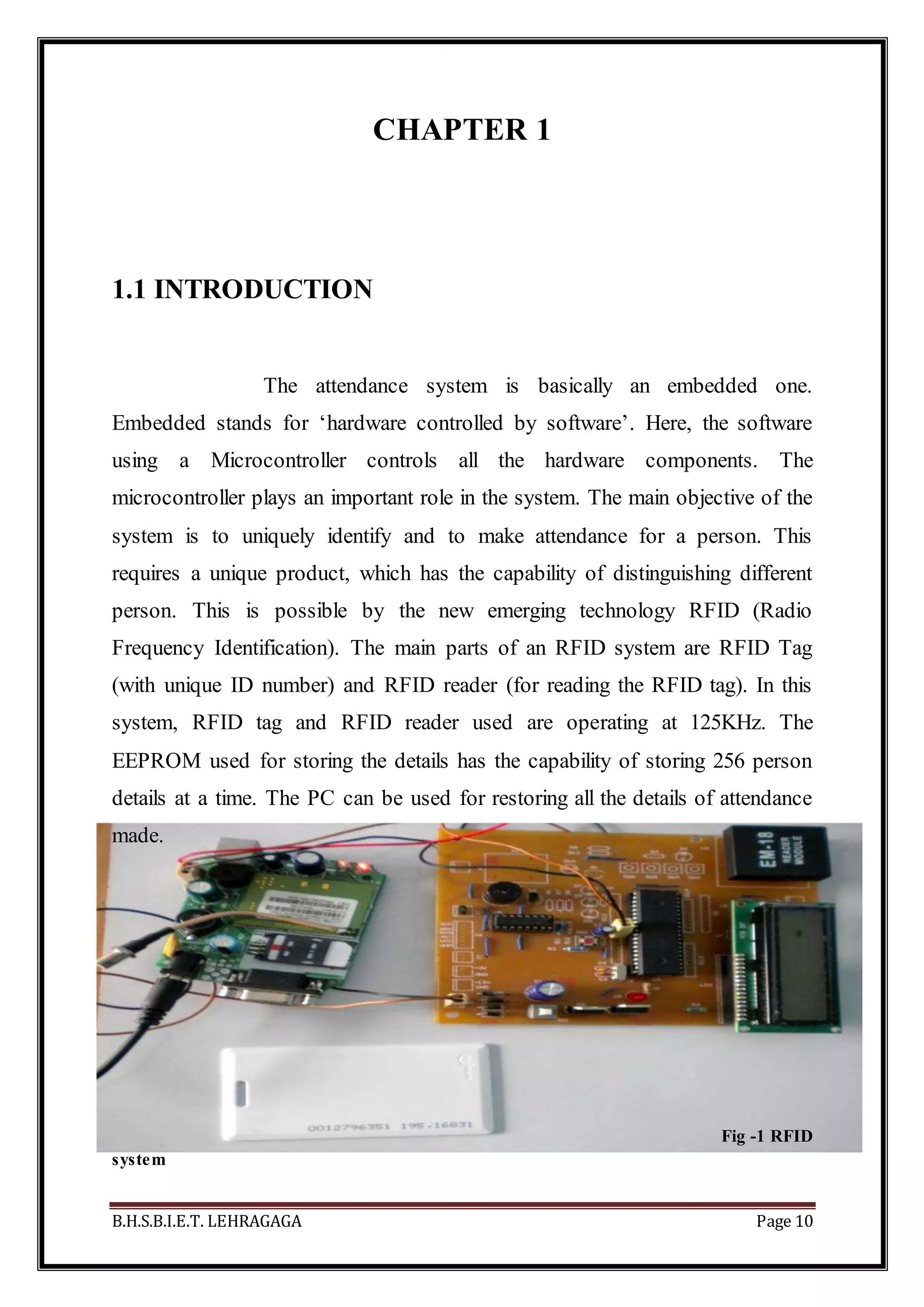


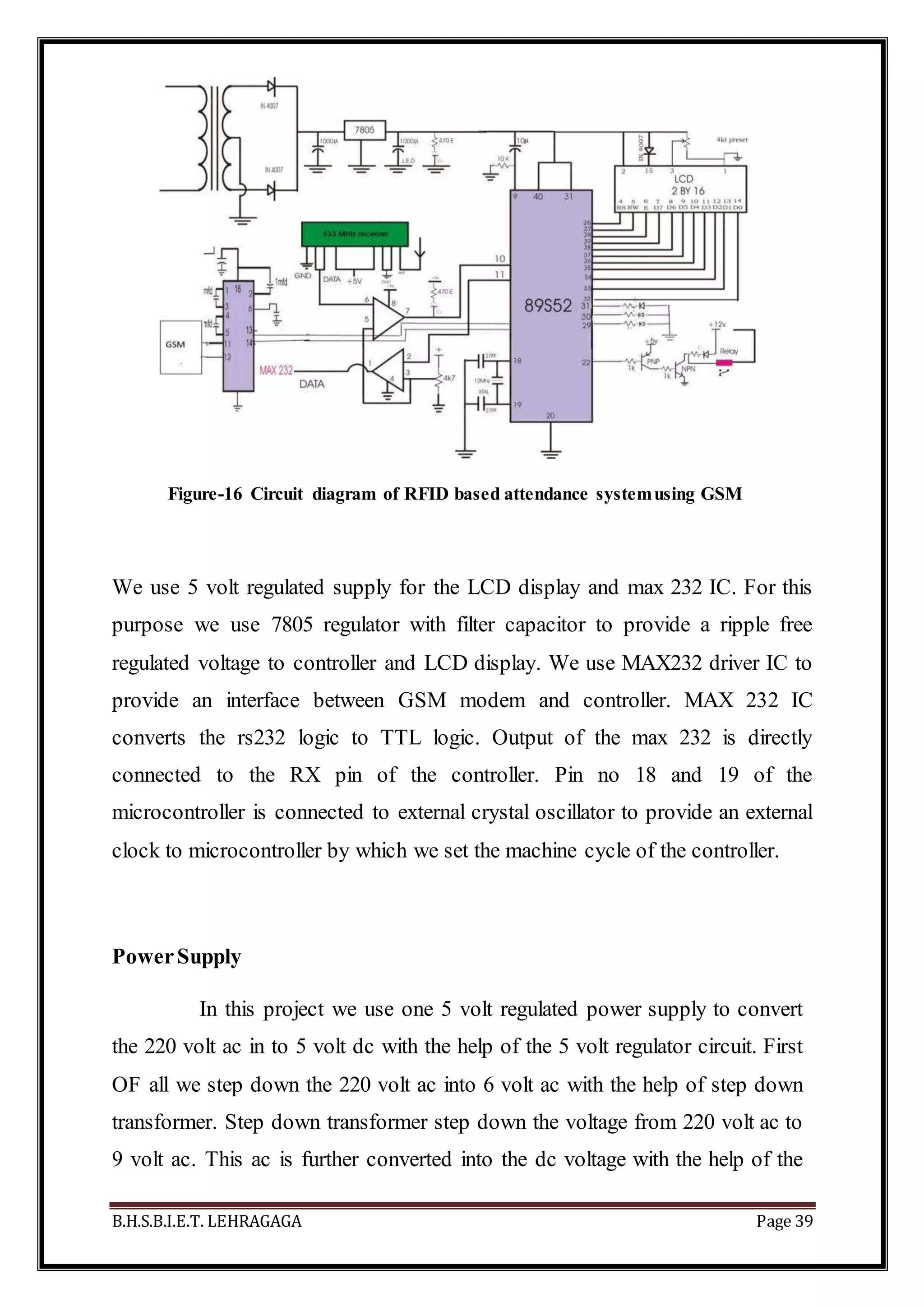
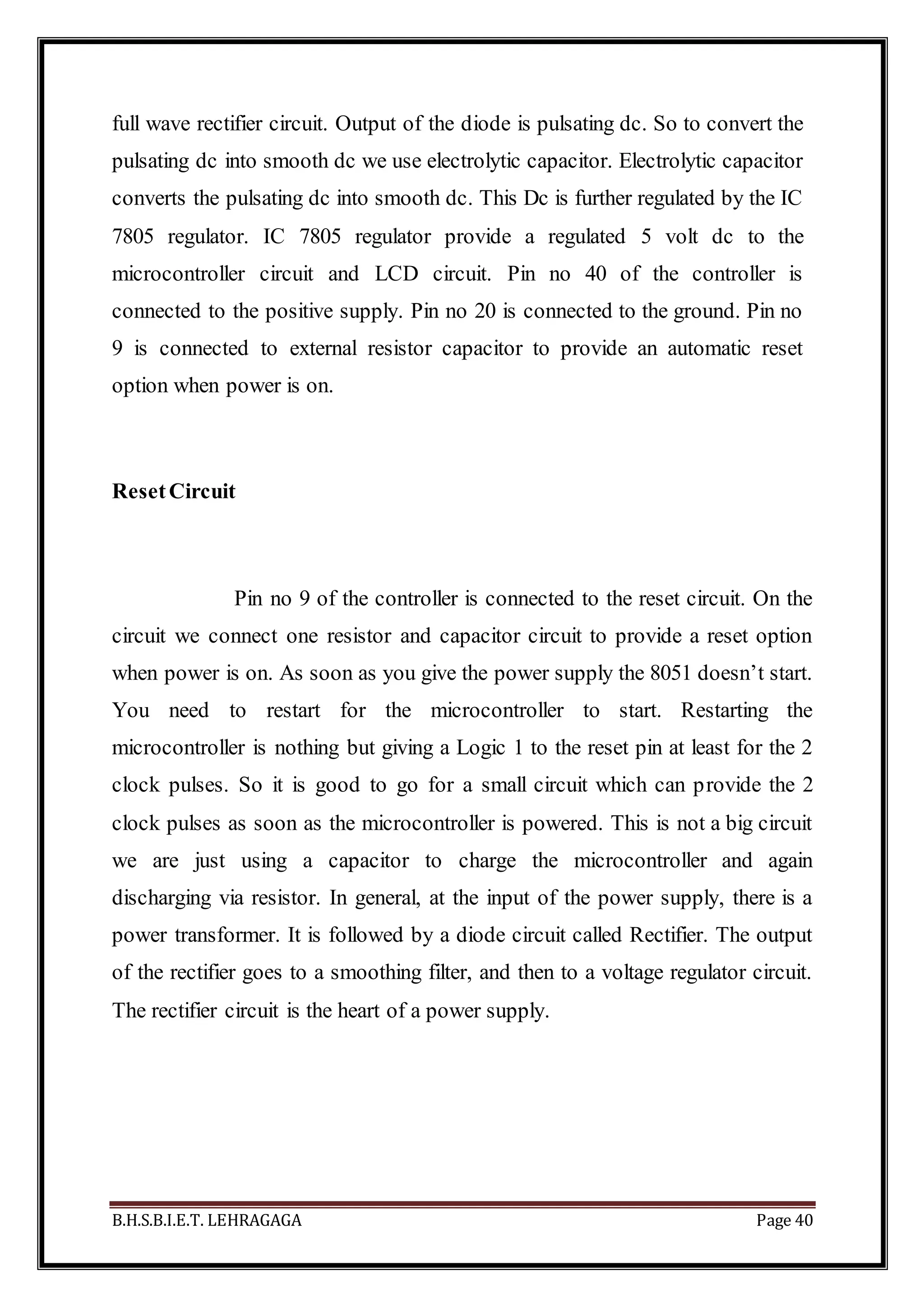


This document is a project report submitted by Govind Kumar Gourav for a Bachelor of Technology degree. It describes the development of a mobile attendance management system using an AT89S52 microcontroller. The system utilizes radio frequency identification (RFID) technology to uniquely identify and record attendance for individuals. The report includes sections on introduction and objectives, literature review, system design and implementation, conclusion, and references.


![5.[26 35] rfid security using mini des algorithm in deployment of bike rentin...](https://cdn.slidesharecdn.com/ss_thumbnails/5-26-35rfidsecurityusingminidesalgorithmindeploymentofbikerentingsystem-111118181644-phpapp01-thumbnail.jpg?width=640&height=640&fit=bounds)