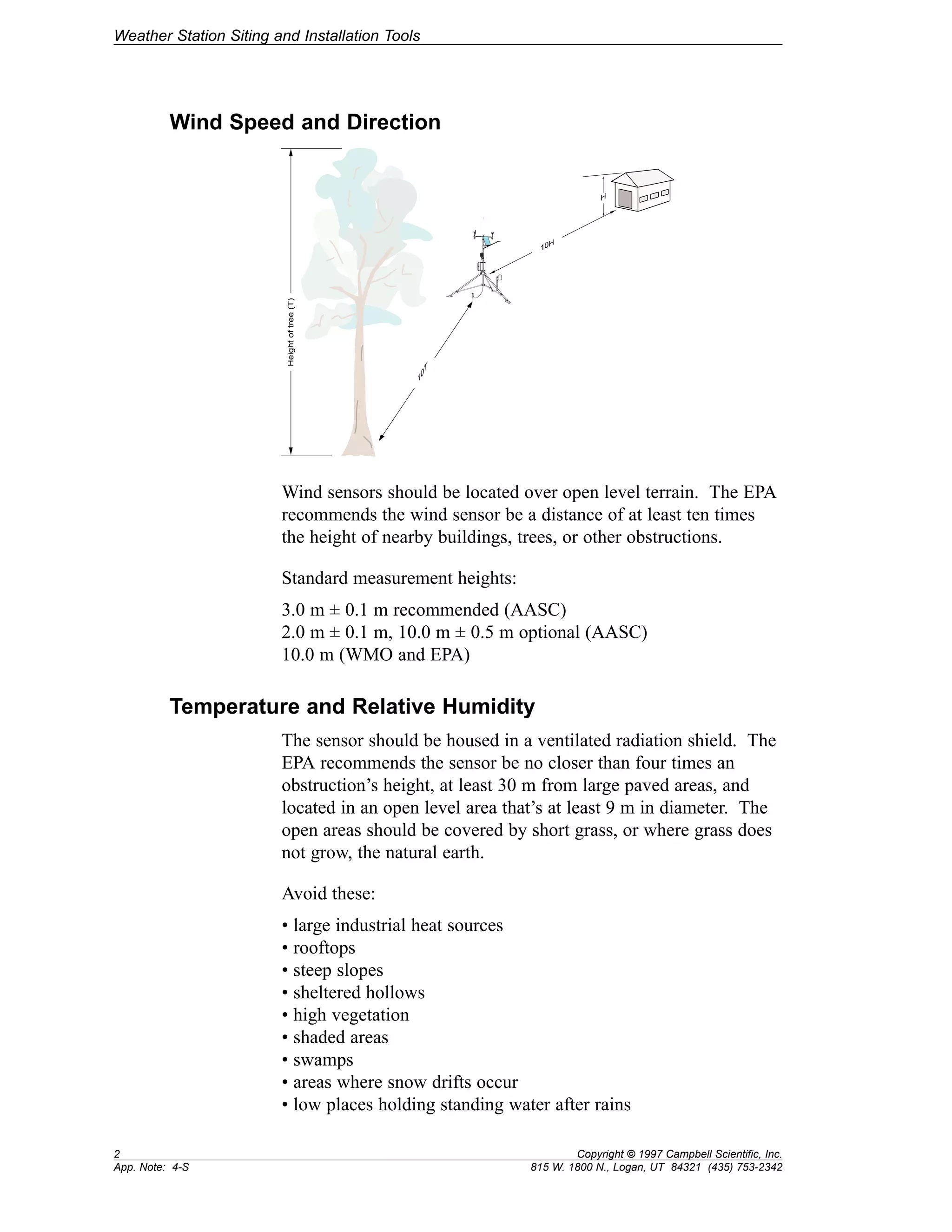
APPLICATION NOTE 
App. Note Code: 4-S 
Weather Station Siting and 
Installation Tools 
815 W. 1800 N. Logan, Utah 84321-1784 (435) 753-2342 FAX (435) 750-9540 
Copyright (C) 1997 Campbell Scientific, Inc.
Weather Station Siting and 
Installation Tools 
This application note describes weather station site selection, sensor placement, and the 
required tools for installation and maintenance. This note is intended as a pre-purchase 
reference. More detailed information about weather station installation is provided by 
our Tripod, UT10, and UT30 installation manuals. 
Siting and Exposure 
Selecting an appropriate site for the weather station is critical for 
obtaining accurate meteorological data. Typically, the site should 
represent the general area of interest, and be away from obstruc-tions 
such as buildings and trees. 
Guidelines condensed from the following publications: 
• The State Climatologist (1985). Publication of the American 
Association of State Climatologists: Heights and Exposure 
Standards for Sensor on Automated Weather Stations, v. 9, No. 
4, October, 1985. 
• EPA (1987). On-Site Meteorological Program Guidance for 
Regulatory Modeling Applications, EPA-450/4-87-013. Office 
of Air Quality Planning and Standards, Research Triangle 
Parks, North Carolina 27711. 
• WMO (1983). Guide to Meteorological Instruments and 
Methods of Observation. World Meteorological Organization 
No. 8, 5th edition, Geneva Switzerland. 
Copyright © 1997 Campbell Scientific, Inc. 1 
815 W. 1800 N., Logan, UT 84321-1784 (435) 753-2342 App. Note: 4-S
Weather Station Siting and Installation Tools 
Wind Speed and Direction 
REGCOMENDED 
Feed SENSORS 
Serial 27115 
Portland Or USA 
REGCOMENDED 
Feed SENSORS 
Serial 27115 
Portland Or USA 
REGCOMENDED 
Feed SENSORS 
Serial 27115 
Portland Or USA 
H 
10H 
10T 
Height of tree (T) 
Wind sensors should be located over open level terrain. The EPA 
recommends the wind sensor be a distance of at least ten times 
the height of nearby buildings, trees, or other obstructions. 
Standard measurement heights: 
3.0 m ± 0.1 m recommended (AASC) 
2.0 m ± 0.1 m, 10.0 m ± 0.5 m optional (AASC) 
10.0 m (WMO and EPA) 
Temperature and Relative Humidity 
The sensor should be housed in a ventilated radiation shield. The 
EPA recommends the sensor be no closer than four times an 
obstruction’s height, at least 30 m from large paved areas, and 
located in an open level area that’s at least 9 m in diameter. The 
open areas should be covered by short grass, or where grass does 
not grow, the natural earth. 
Avoid these: 
• large industrial heat sources 
• rooftops 
• steep slopes 
• sheltered hollows 
• high vegetation 
• shaded areas 
• swamps 
• areas where snow drifts occur 
• low places holding standing water after rains 
2 Copyright © 1997 Campbell Scientific, Inc. 
App. Note: 4-S 815 W. 1800 N., Logan, UT 84321 (435) 753-2342
Weather Station Siting and Installation Tools 
Standard measurement heights: 
1.5 m ± 1.0 m (AASC) 
1.25 to 2.0 m (WMO) 
2.0 m temperature (EPA) 
2.0 m and 10.0 m for temperature difference (EPA) 
Precipitation 
The AASC and EPA suggest tipping buckets be no closer than 
four times the height of an obstruction. The orifice of the gage 
must be in a horizontal plane, open to the sky, and above the level 
of in-splashing and snow accumulation. Typically, tipping buck-ets 
are sited on level ground covered with short grass or gravel. 
Wind shields, such as those used by the National Weather Service, 
are recommended for open areas. 
Standard measurement heights: 
1.0 m ± 1.0 cm (AASC) 
30.0 cm minimum (WMO, EPA) 
Solar Radiation 
Pyranometers should be mounted away from shadows, reflective 
surfaces, and sources of artificial radiation. Mounting the 
pyranometer on the southernmost (northern hemisphere) part 
(either crossarm or pyranometer mounting arm) of the weather 
station should minimize shading from the other weather station 
structures. The height the sensor is mounted is not critical for the 
accuracy of the measurement. However, pyranometers mounted 
at heights of 3 m or less are easier to level and clean. 
Soil Temperature 
The measurement site for soil temperature should be at least 1 m2 
and typical of the surface of interest. The ground surface should 
be level with respect to the immediate area (10 m radius). 
Standard measurement depths: 
10.0 cm ± 1.0 cm (AASC) 
5.0 cm, 10.0 cm, 50.0 cm, 100.0 cm (WMO) 
Copyright © 1997 Campbell Scientific, Inc. 3 
815 W. 1800 N., Logan, UT 84321-1784 (435) 753-2342 App. Note: 4-S
Weather Station Siting and Installation Tools 
Standard Tools for Installation and Maintenance 
User-supplied key for enclosure lock 
Magnetic declination angle for site 
Tape measure: 
12 feet (CM6 / CM10, UT10) 
20 feet (UT30) 
Open-end wrenches: 3/8”, 7/16”, 1/2”, (2) 9/16” 
Level: 
12” to 24” (CM6 / CM10) 
24” to 48” (UT10/UT30) 
Pliers 
Magnetic compass 
12” pipe wrench 
Hammer 
Small sledge (CM10, UT30) 
Claw (UT10) 
Felt-tipped marking pen 
Socket wrench and 7/16” deep well socket 
Allen wrench set (English units) 
Straight-bit screwdrivers (small, medium, large) 
Phillips head screwdrivers (small, medium) 
Small diagonal side-cuts 
Needle-nosed pliers 
Wire strippers 
Pocket knife 
Calculator 
Volt/Ohm meter 
Electrical tape 
6’ stepladder 
Datalogger prompt sheet and manuals 
Station log and pen 
Wire ties and tabs 
Desiccant 
UT30 Only 
Climbing harness 
Hard hats 
50’ haul rope 
Crescent wrench 
“Channel-lock” pliers 
3/8” nut driver 
4 Copyright © 1997 Campbell Scientific, Inc. 
App. Note: 4-S 815 W. 1800 N., Logan, UT 84321 (435) 753-2342
Weather Station Siting and Installation Tools 
Special Tools for Installation Only 
Lock for enclosure 
Shovel 
Rake 
Pick / digging bar 
Teflon tape or pipe dope 
Conduit and associated tools (as required) 
1/4” washers - often required as spacers for u-bolts (UT10/UT30) 
UT10 Only 
Hand saw 
Materials for concrete form: 
(4) 12” wood stakes 
(1) 2” x 4” x 8” piece of lumber 
(8) 8p double-head nails 
(8) 16p double-head nails 
Concrete trowels 
(2) 1.0 to 1.5” thick x 24” boards to support base above 
forms (optional) 
UT30 Only 
(4) 12” wood stakes 
20’ non-stretch line 
Wire rope cutters (hammer and cold chisel will work) 
For B18 Base and UTEYE Anchors: 
Pick or digging bar 
Optional: 
Concrete form material: 2” x 4” lumber, stakes, 
saw, hammer, nails, etc. 
Concrete trowels 
For UTDUK Duckbill Anchors: 
Sledgehammer 
Highlift jack 
Chain (to attach jack to anchor loops) 
For RFM18 Base: 
(3) anchors appropriate for mounting surface 
(3) bolts and washers to secure base to anchors 
Copyright © 1997 Campbell Scientific, Inc. 5 
815 W. 1800 N., Logan, UT 84321-1784 (435) 753-2342 App. Note: 4-S

Weather Station Siting and Installation Tools App Note Code 4-S 1997

  • 1.
    APPLICATION NOTE App.Note Code: 4-S Weather Station Siting and Installation Tools 815 W. 1800 N. Logan, Utah 84321-1784 (435) 753-2342 FAX (435) 750-9540 Copyright (C) 1997 Campbell Scientific, Inc.
  • 3.
    Weather Station Sitingand Installation Tools This application note describes weather station site selection, sensor placement, and the required tools for installation and maintenance. This note is intended as a pre-purchase reference. More detailed information about weather station installation is provided by our Tripod, UT10, and UT30 installation manuals. Siting and Exposure Selecting an appropriate site for the weather station is critical for obtaining accurate meteorological data. Typically, the site should represent the general area of interest, and be away from obstruc-tions such as buildings and trees. Guidelines condensed from the following publications: • The State Climatologist (1985). Publication of the American Association of State Climatologists: Heights and Exposure Standards for Sensor on Automated Weather Stations, v. 9, No. 4, October, 1985. • EPA (1987). On-Site Meteorological Program Guidance for Regulatory Modeling Applications, EPA-450/4-87-013. Office of Air Quality Planning and Standards, Research Triangle Parks, North Carolina 27711. • WMO (1983). Guide to Meteorological Instruments and Methods of Observation. World Meteorological Organization No. 8, 5th edition, Geneva Switzerland. Copyright © 1997 Campbell Scientific, Inc. 1 815 W. 1800 N., Logan, UT 84321-1784 (435) 753-2342 App. Note: 4-S
  • 4.
    Weather Station Sitingand Installation Tools Wind Speed and Direction REGCOMENDED Feed SENSORS Serial 27115 Portland Or USA REGCOMENDED Feed SENSORS Serial 27115 Portland Or USA REGCOMENDED Feed SENSORS Serial 27115 Portland Or USA H 10H 10T Height of tree (T) Wind sensors should be located over open level terrain. The EPA recommends the wind sensor be a distance of at least ten times the height of nearby buildings, trees, or other obstructions. Standard measurement heights: 3.0 m ± 0.1 m recommended (AASC) 2.0 m ± 0.1 m, 10.0 m ± 0.5 m optional (AASC) 10.0 m (WMO and EPA) Temperature and Relative Humidity The sensor should be housed in a ventilated radiation shield. The EPA recommends the sensor be no closer than four times an obstruction’s height, at least 30 m from large paved areas, and located in an open level area that’s at least 9 m in diameter. The open areas should be covered by short grass, or where grass does not grow, the natural earth. Avoid these: • large industrial heat sources • rooftops • steep slopes • sheltered hollows • high vegetation • shaded areas • swamps • areas where snow drifts occur • low places holding standing water after rains 2 Copyright © 1997 Campbell Scientific, Inc. App. Note: 4-S 815 W. 1800 N., Logan, UT 84321 (435) 753-2342
  • 5.
    Weather Station Sitingand Installation Tools Standard measurement heights: 1.5 m ± 1.0 m (AASC) 1.25 to 2.0 m (WMO) 2.0 m temperature (EPA) 2.0 m and 10.0 m for temperature difference (EPA) Precipitation The AASC and EPA suggest tipping buckets be no closer than four times the height of an obstruction. The orifice of the gage must be in a horizontal plane, open to the sky, and above the level of in-splashing and snow accumulation. Typically, tipping buck-ets are sited on level ground covered with short grass or gravel. Wind shields, such as those used by the National Weather Service, are recommended for open areas. Standard measurement heights: 1.0 m ± 1.0 cm (AASC) 30.0 cm minimum (WMO, EPA) Solar Radiation Pyranometers should be mounted away from shadows, reflective surfaces, and sources of artificial radiation. Mounting the pyranometer on the southernmost (northern hemisphere) part (either crossarm or pyranometer mounting arm) of the weather station should minimize shading from the other weather station structures. The height the sensor is mounted is not critical for the accuracy of the measurement. However, pyranometers mounted at heights of 3 m or less are easier to level and clean. Soil Temperature The measurement site for soil temperature should be at least 1 m2 and typical of the surface of interest. The ground surface should be level with respect to the immediate area (10 m radius). Standard measurement depths: 10.0 cm ± 1.0 cm (AASC) 5.0 cm, 10.0 cm, 50.0 cm, 100.0 cm (WMO) Copyright © 1997 Campbell Scientific, Inc. 3 815 W. 1800 N., Logan, UT 84321-1784 (435) 753-2342 App. Note: 4-S
  • 6.
    Weather Station Sitingand Installation Tools Standard Tools for Installation and Maintenance User-supplied key for enclosure lock Magnetic declination angle for site Tape measure: 12 feet (CM6 / CM10, UT10) 20 feet (UT30) Open-end wrenches: 3/8”, 7/16”, 1/2”, (2) 9/16” Level: 12” to 24” (CM6 / CM10) 24” to 48” (UT10/UT30) Pliers Magnetic compass 12” pipe wrench Hammer Small sledge (CM10, UT30) Claw (UT10) Felt-tipped marking pen Socket wrench and 7/16” deep well socket Allen wrench set (English units) Straight-bit screwdrivers (small, medium, large) Phillips head screwdrivers (small, medium) Small diagonal side-cuts Needle-nosed pliers Wire strippers Pocket knife Calculator Volt/Ohm meter Electrical tape 6’ stepladder Datalogger prompt sheet and manuals Station log and pen Wire ties and tabs Desiccant UT30 Only Climbing harness Hard hats 50’ haul rope Crescent wrench “Channel-lock” pliers 3/8” nut driver 4 Copyright © 1997 Campbell Scientific, Inc. App. Note: 4-S 815 W. 1800 N., Logan, UT 84321 (435) 753-2342
  • 7.
    Weather Station Sitingand Installation Tools Special Tools for Installation Only Lock for enclosure Shovel Rake Pick / digging bar Teflon tape or pipe dope Conduit and associated tools (as required) 1/4” washers - often required as spacers for u-bolts (UT10/UT30) UT10 Only Hand saw Materials for concrete form: (4) 12” wood stakes (1) 2” x 4” x 8” piece of lumber (8) 8p double-head nails (8) 16p double-head nails Concrete trowels (2) 1.0 to 1.5” thick x 24” boards to support base above forms (optional) UT30 Only (4) 12” wood stakes 20’ non-stretch line Wire rope cutters (hammer and cold chisel will work) For B18 Base and UTEYE Anchors: Pick or digging bar Optional: Concrete form material: 2” x 4” lumber, stakes, saw, hammer, nails, etc. Concrete trowels For UTDUK Duckbill Anchors: Sledgehammer Highlift jack Chain (to attach jack to anchor loops) For RFM18 Base: (3) anchors appropriate for mounting surface (3) bolts and washers to secure base to anchors Copyright © 1997 Campbell Scientific, Inc. 5 815 W. 1800 N., Logan, UT 84321-1784 (435) 753-2342 App. Note: 4-S