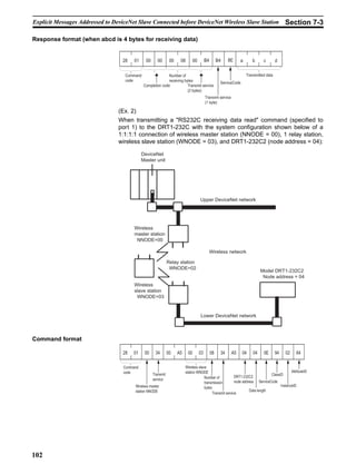
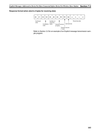
Downloaded 33 times


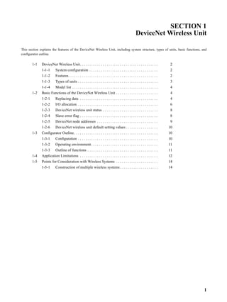


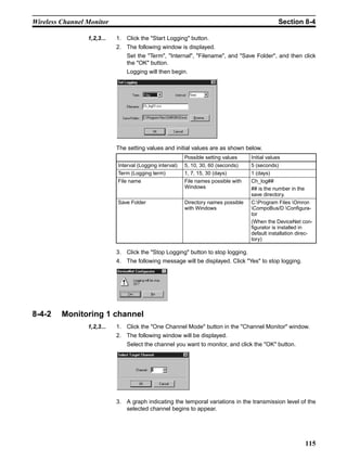
![Remote I/O Communications Performances Section 9-1
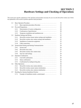
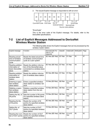
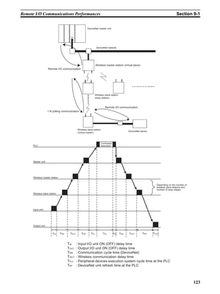
Note For details on the Input I/O Unit input delay time and the Output I/O Unit out-
put delay time, refer to the information in the "DeviceNet Slave Manual"; for
details on the communication cycle and refresh processing time, refer to the
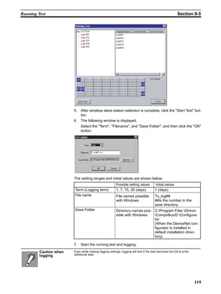
information of the remote I/O communication performance in the "DeviceNet
User’s Manual". Refer to the PLC Operation Manual for details on the PLC
cycle time.
The maximum I/O response time (T MAX) can be obtained from the following
expression:
TMAX = TIN +TOUT +4 × TRM +2 × TWCY +2 × TPLC +TRF
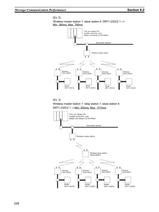
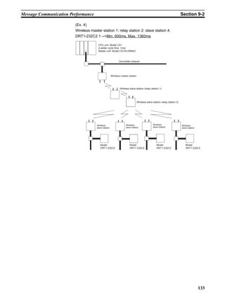
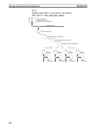
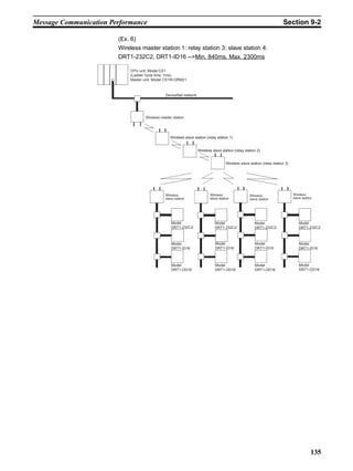
9-1-2 Wireless communication cycle time (TWCY)
Wireless communication delay time occurs in a wireless network when using
wireless units. The wireless communication delay time becomes longer
depending on the increase in the number of wireless slave stations and relay
stages. The unit is ms.
TWCY =Σ (Total cycle time of wireless slave stations)
WNODE
=Σ [{(TX_LEN<WNODE>+RX_LEN<WNODE>)/12+2+2} (No. of relay stages+1)]
WNODE
Command send overhead
Response send overhead
TX_LEN<WNODE>: Command data length
RX_LEN<WNODE>: Response data length
TX_LEN<WNODE>=29+OUTSIZE [byte] + No. of relay stages(No. of stages = byte)
Command header
RX_LEN<WNODE>=41+INSIZE [byte] + No. of relay stages (No. of stages = byte)
Response header
OUTSIZE [byte]: Add 1, if an odd number results when even numbers, slave 8-point
output, etc. are used.
INSIZE [byte]: Add 1, if an odd number results when even numbers, slave 8-point
input, etc. are used.
9-1-3 Actually measured reference data
Use the following values of the I/O response time (IN input -PLC processing -
OUT output) measured by the OMRON system test as reference.
The data described is the smallest and largest values resulting from 30 times
of continuous testing. The actual measurements could be longer than the
largest value depending on the environment where the measurements were
taken. Thus, use the results only as a reference.
124](https://image.slidesharecdn.com/wd3-121223095244-phpapp01/85/Wd3_OMRON_jm-137-320.jpg)


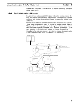
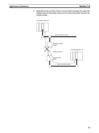
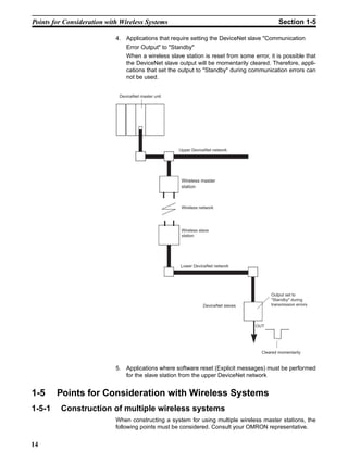
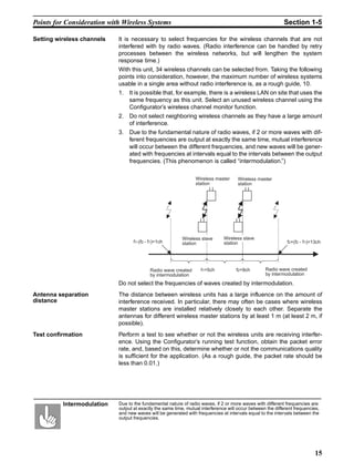
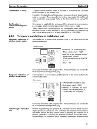
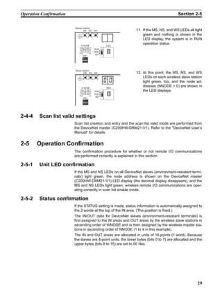
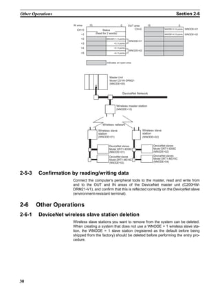
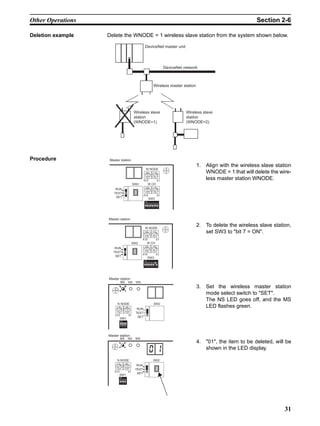
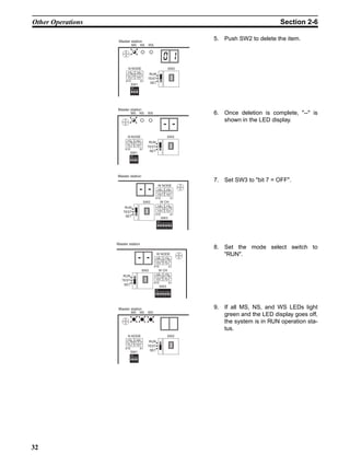
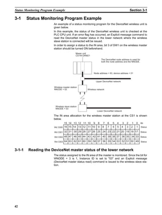
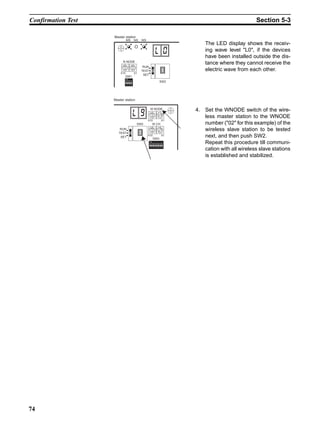
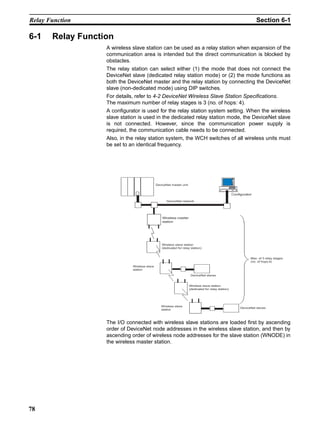
1. The document provides an introduction and safety information for using a DeviceNet wireless unit. It describes the basic functions and components of the DeviceNet wireless system, including the master unit, slave stations, and configurator software. 2. Safety precautions that must be followed when using the DeviceNet wireless unit are outlined, such as not using it for real-time control, avoiding excess vibration/shock, and proper installation. 3. Guidelines for proper use of the equipment are given, including instructions to turn off power before wiring, fix the unit securely, avoid direct sunlight/water exposure, and consider potential interference from other wireless devices.