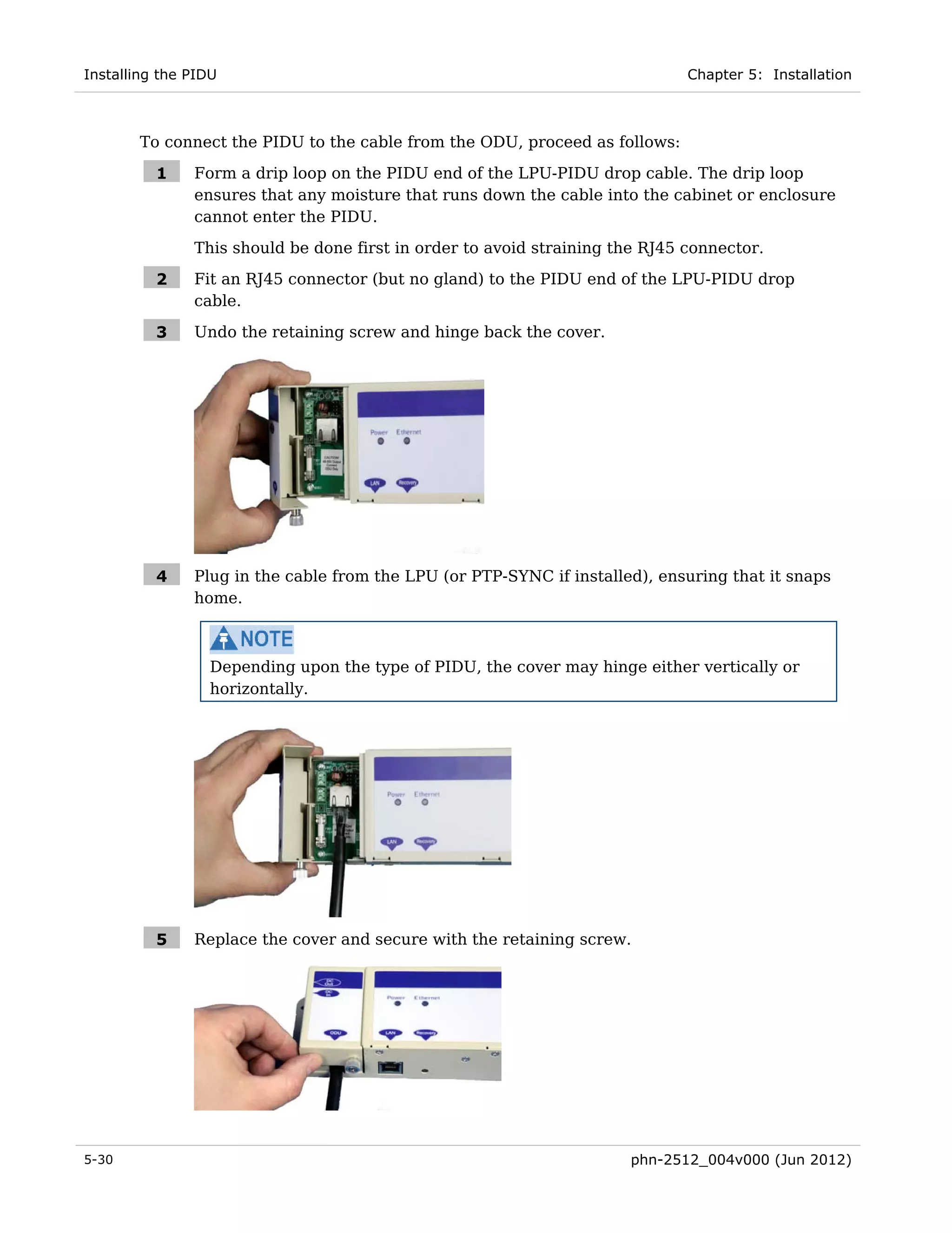
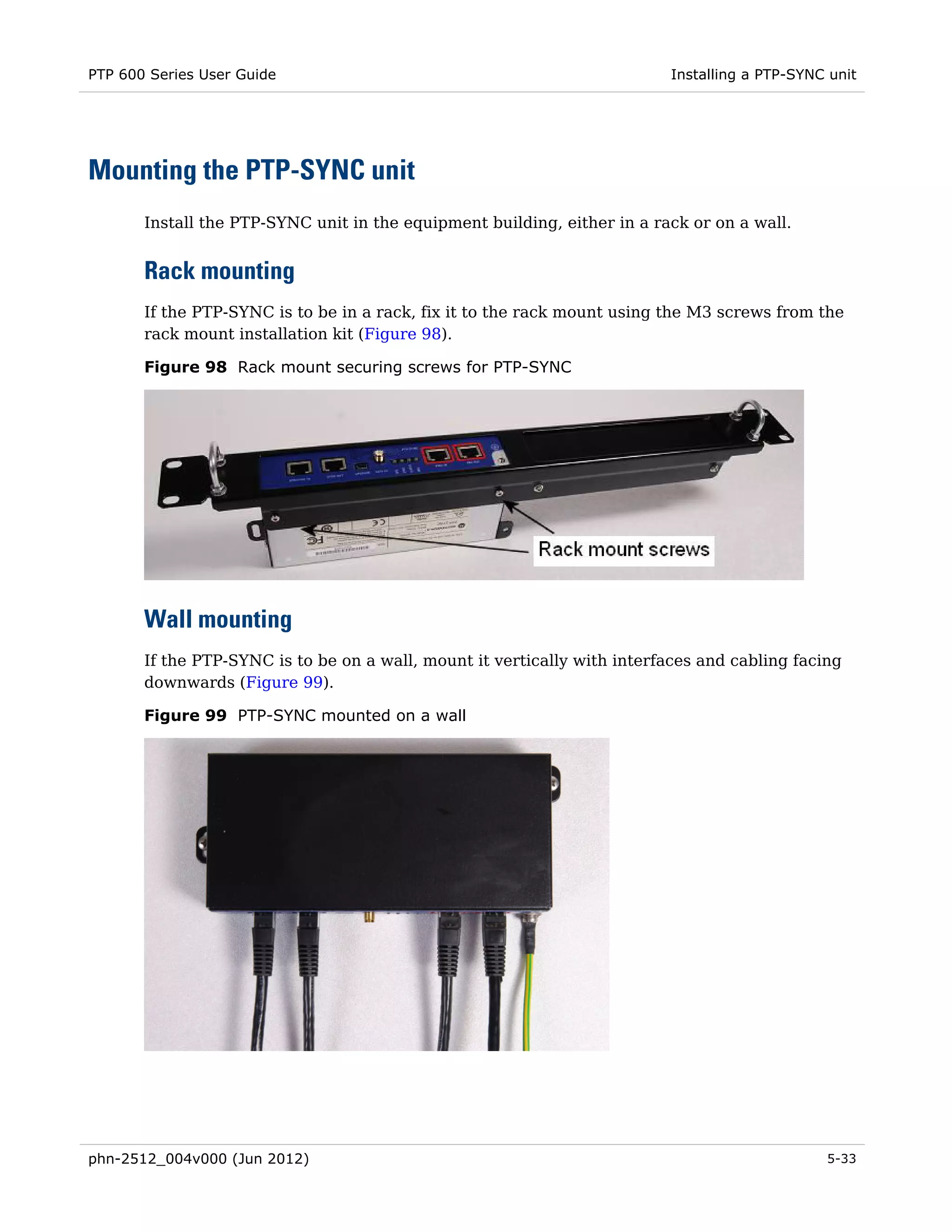
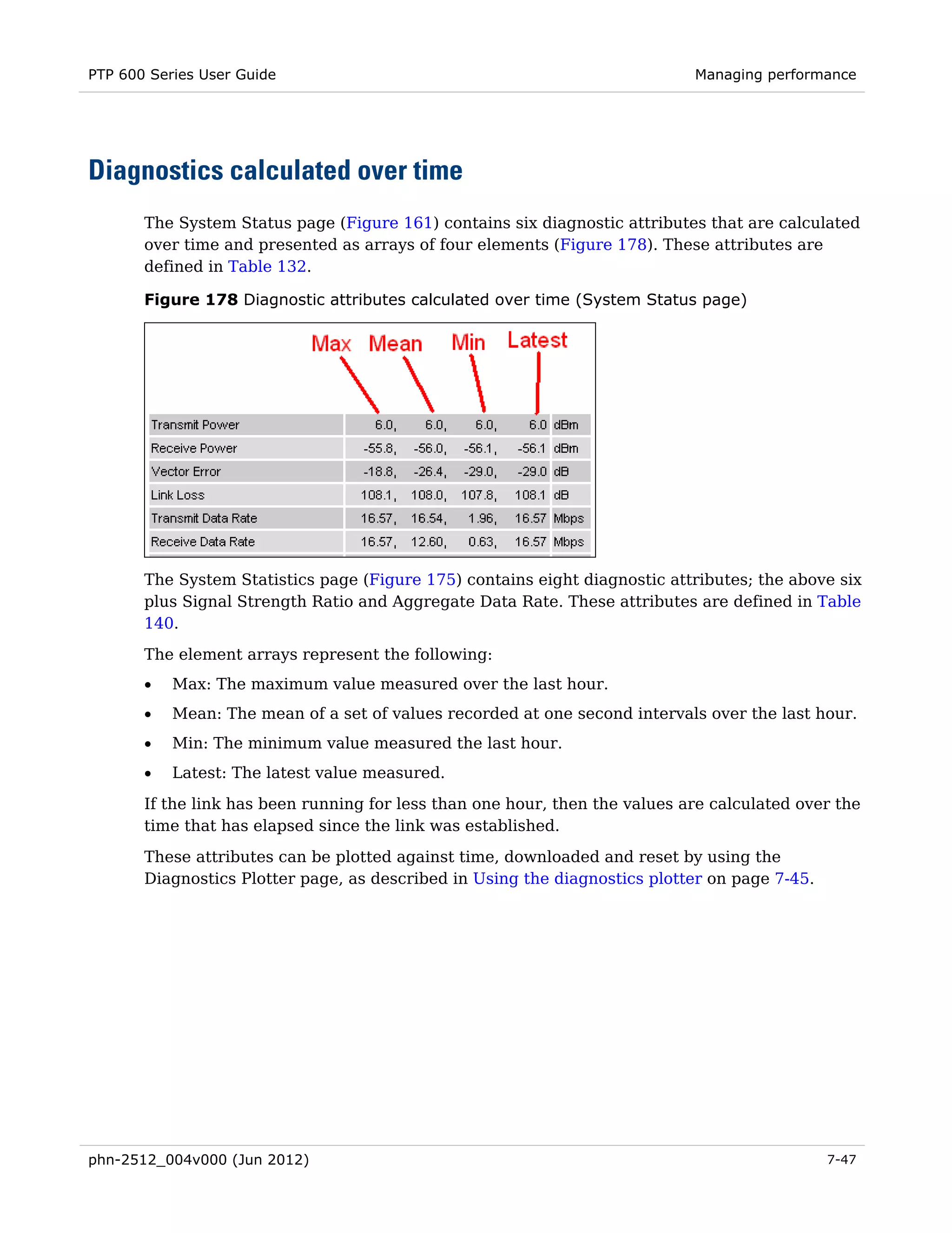
Downloaded 19 times


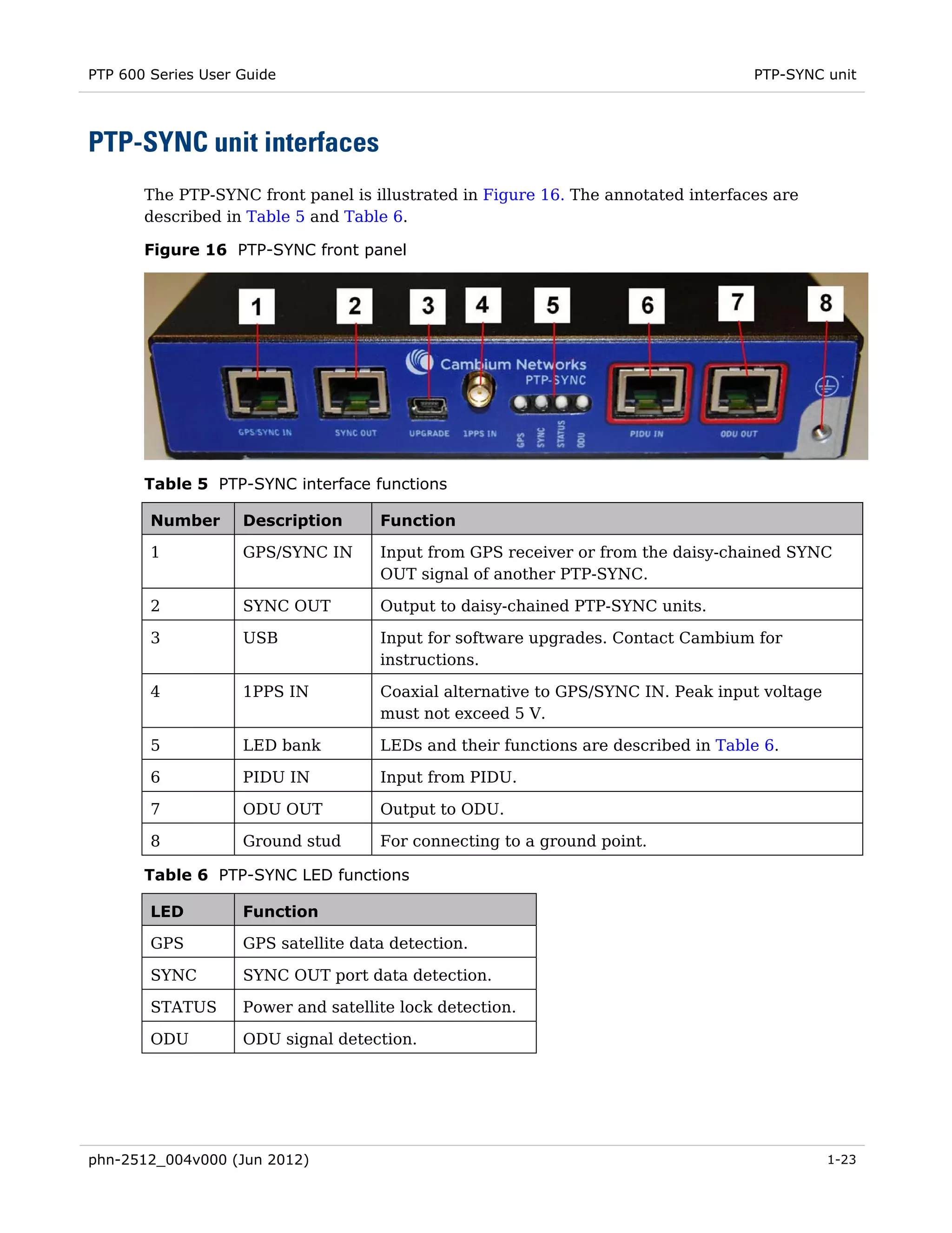
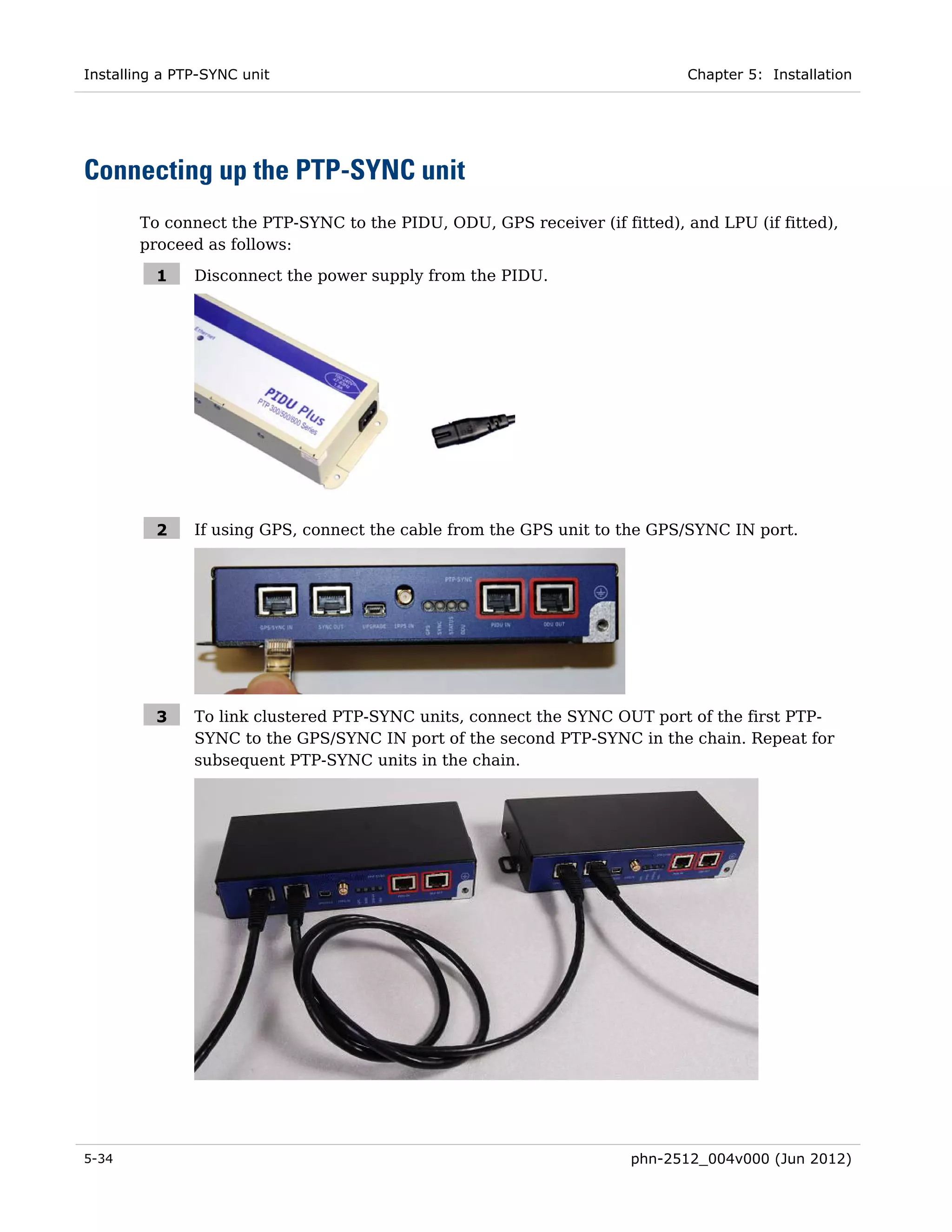
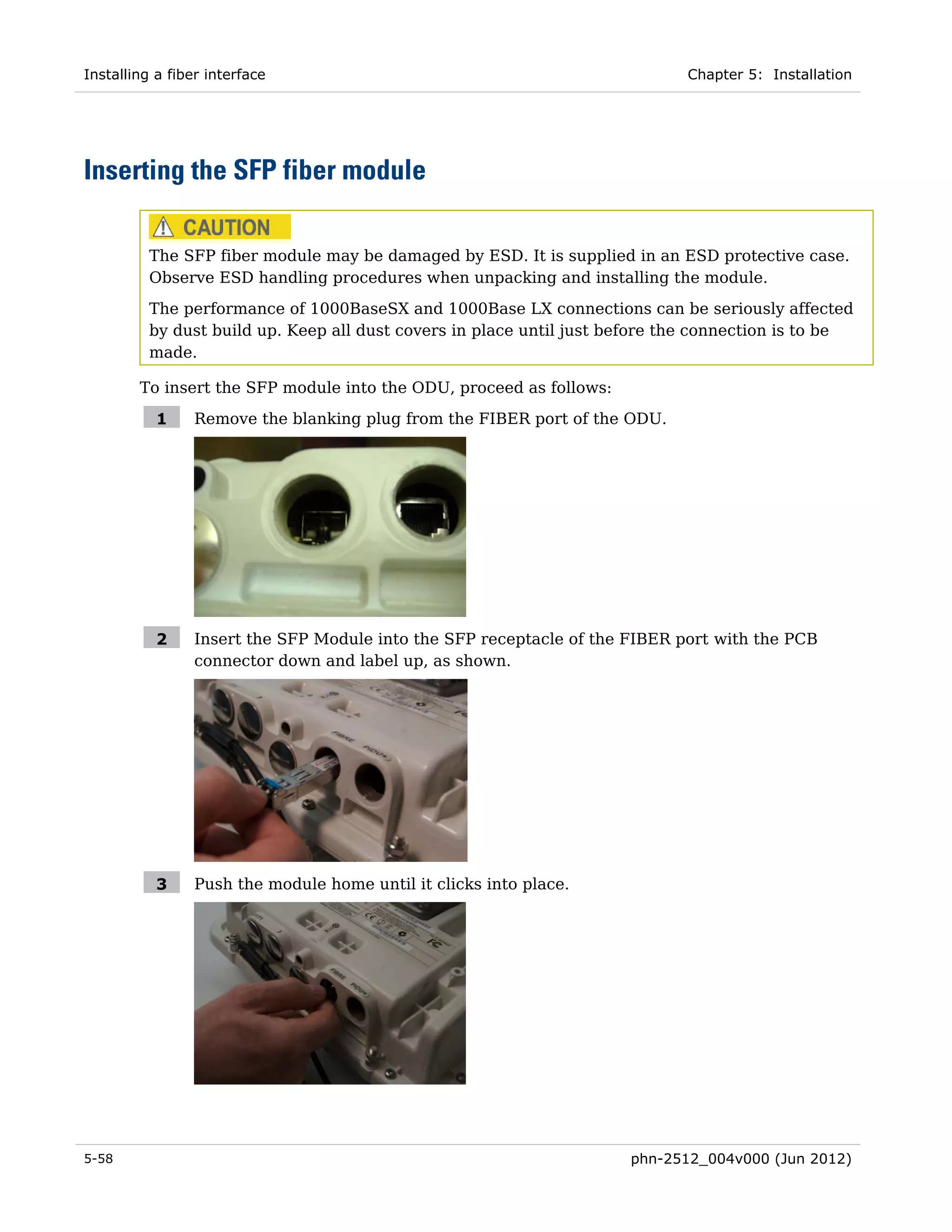
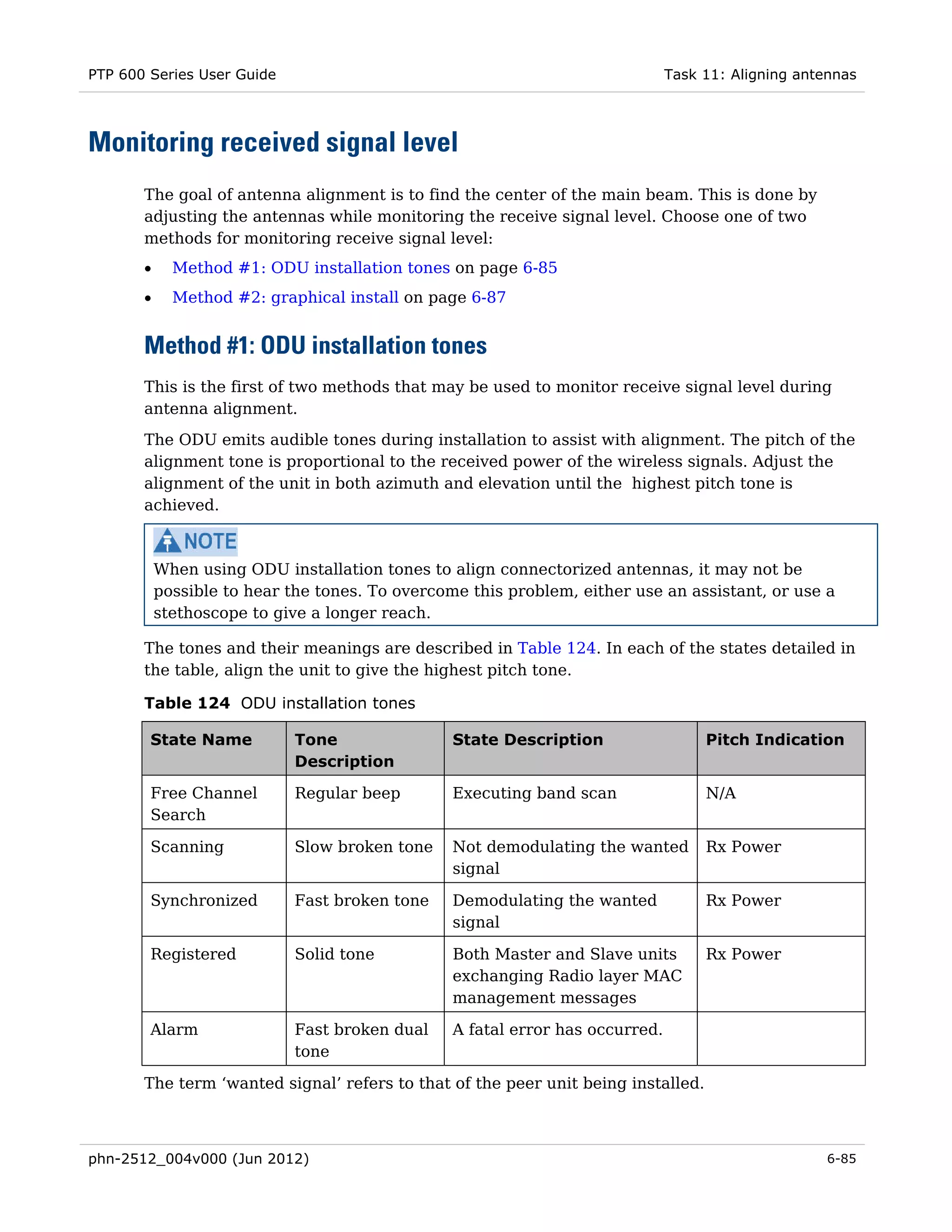
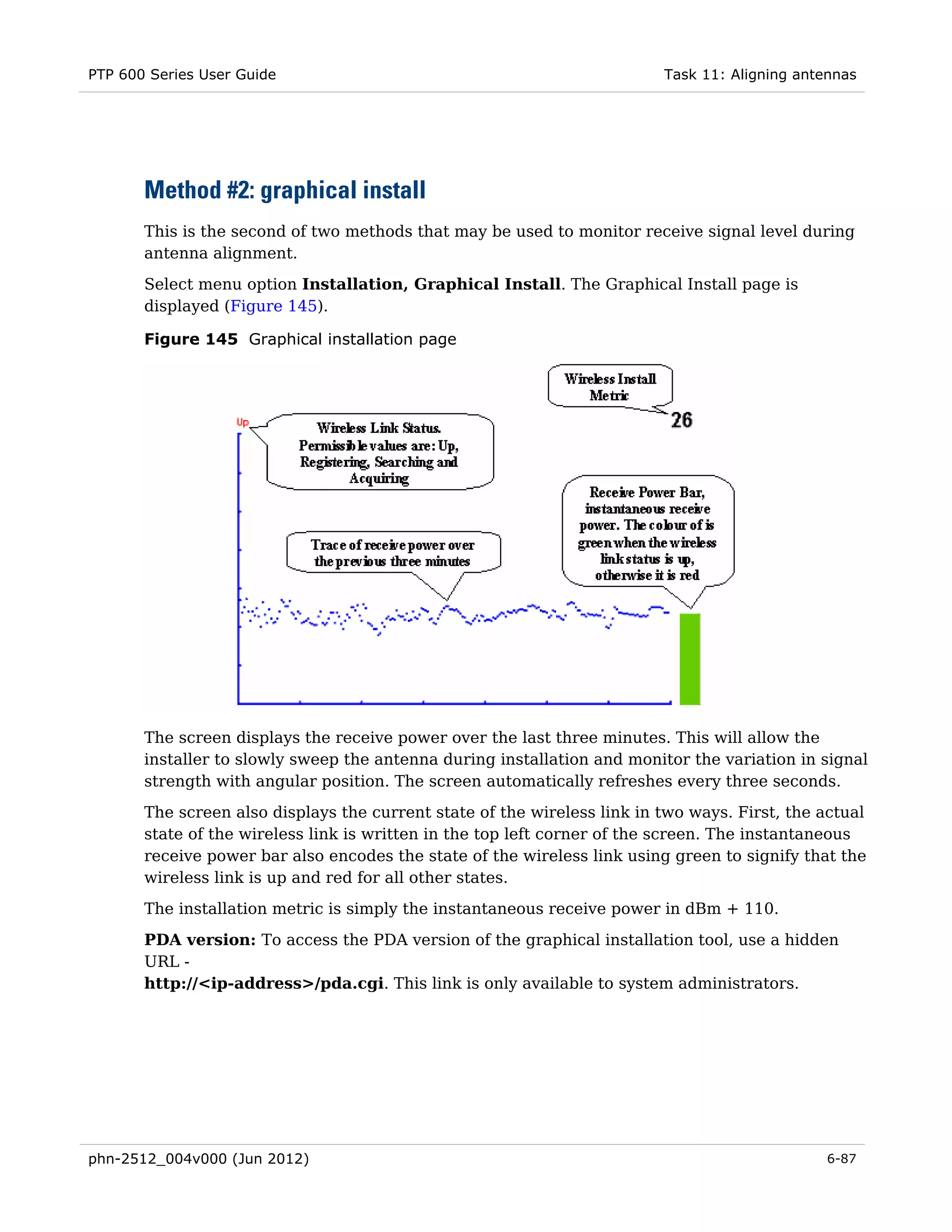
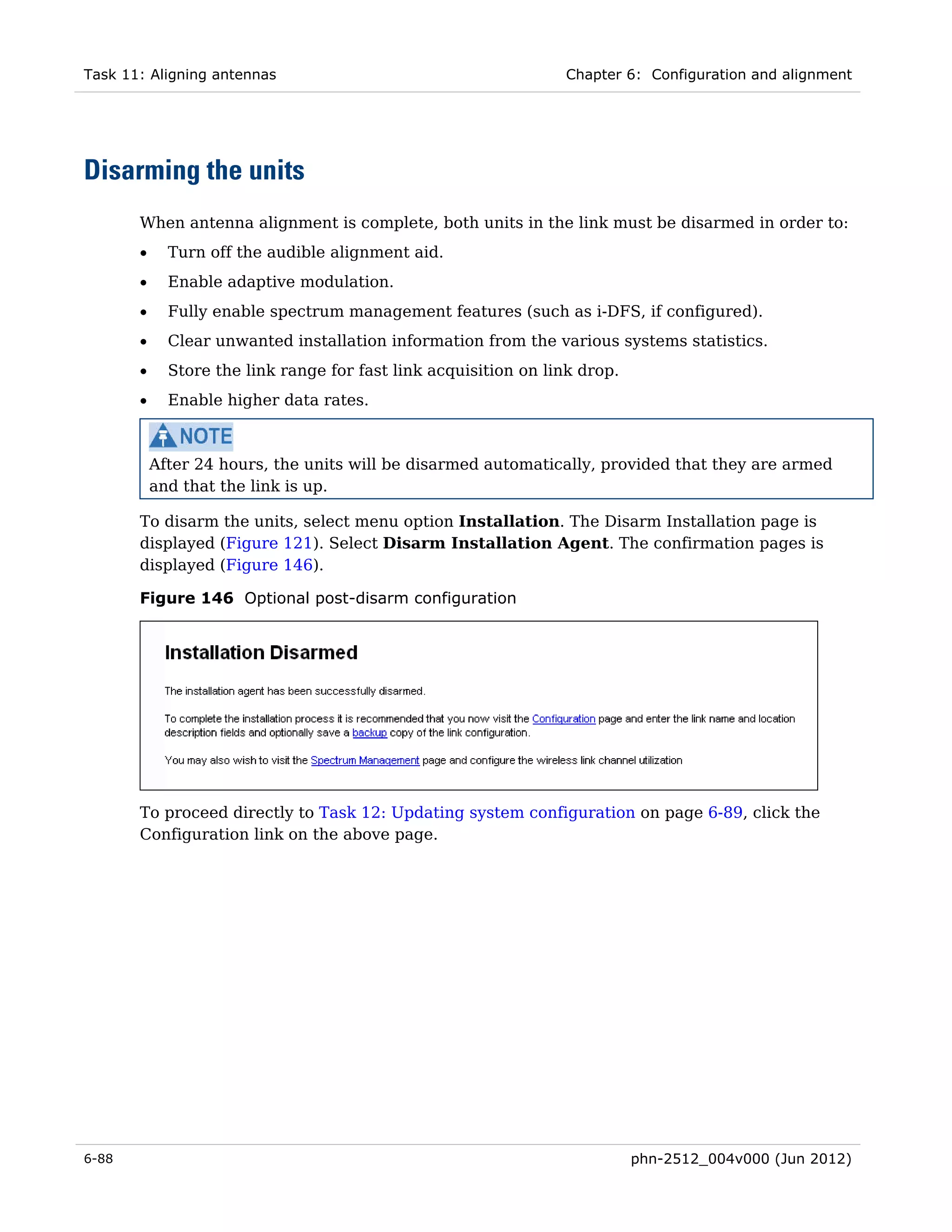
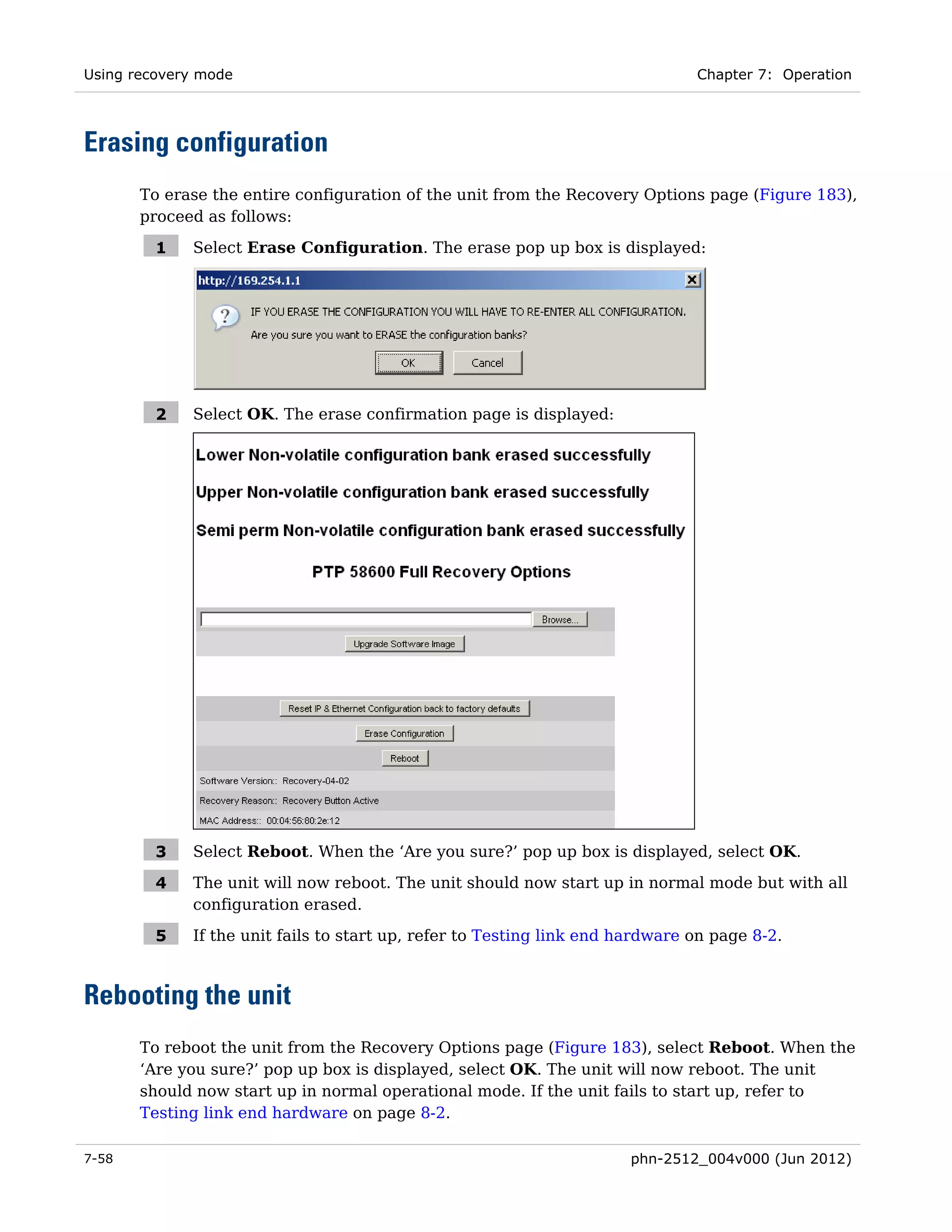
![PTP 600 Series User Guide Security planning
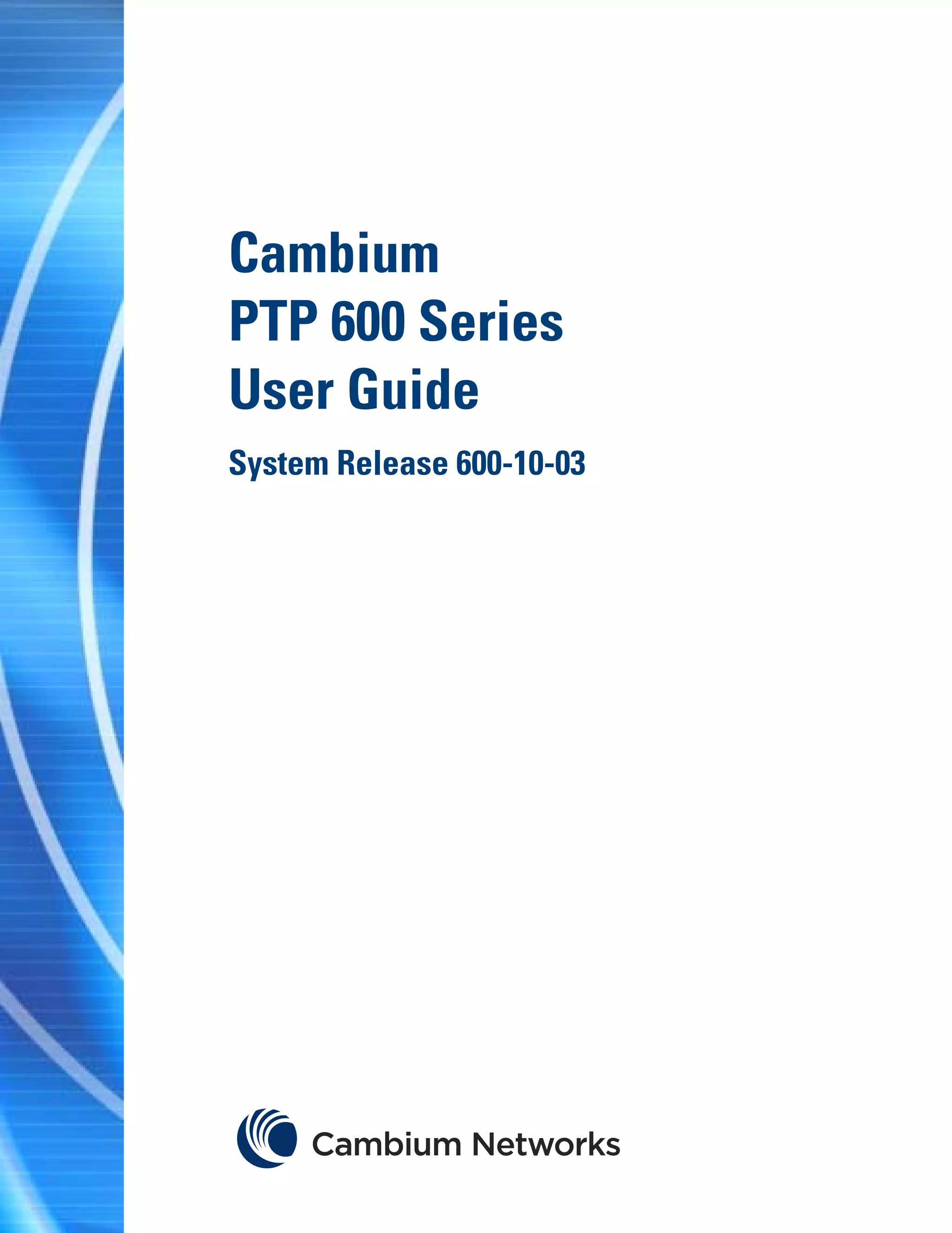
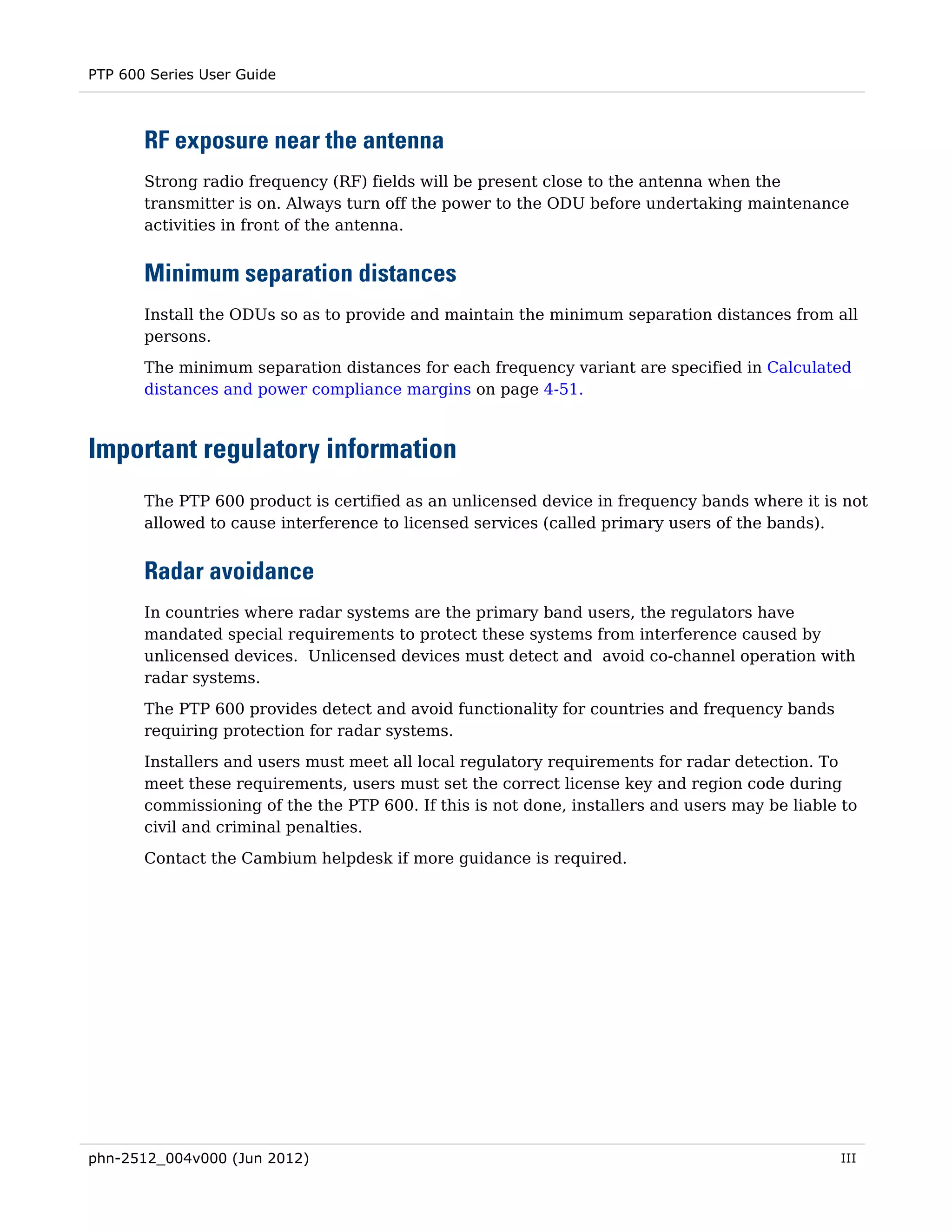
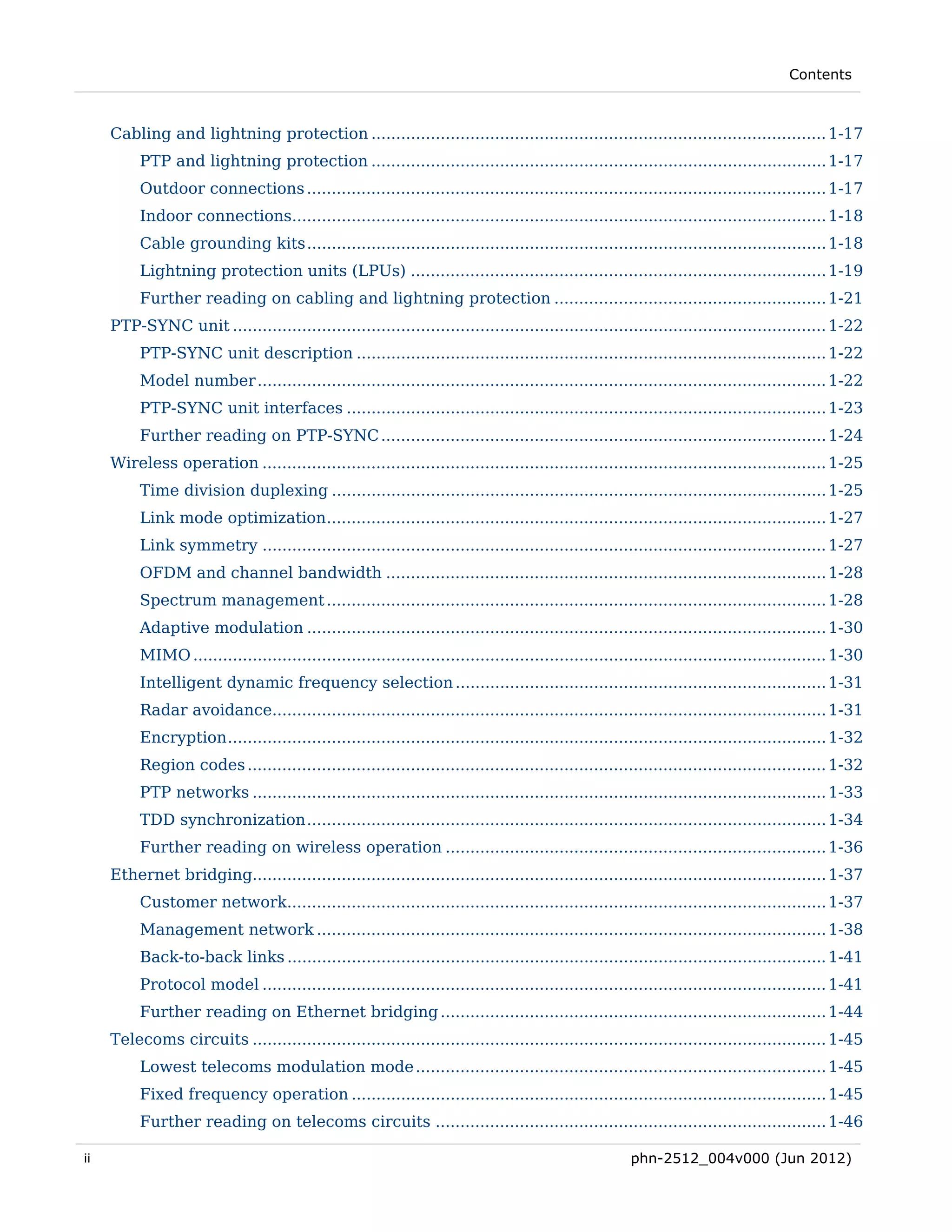
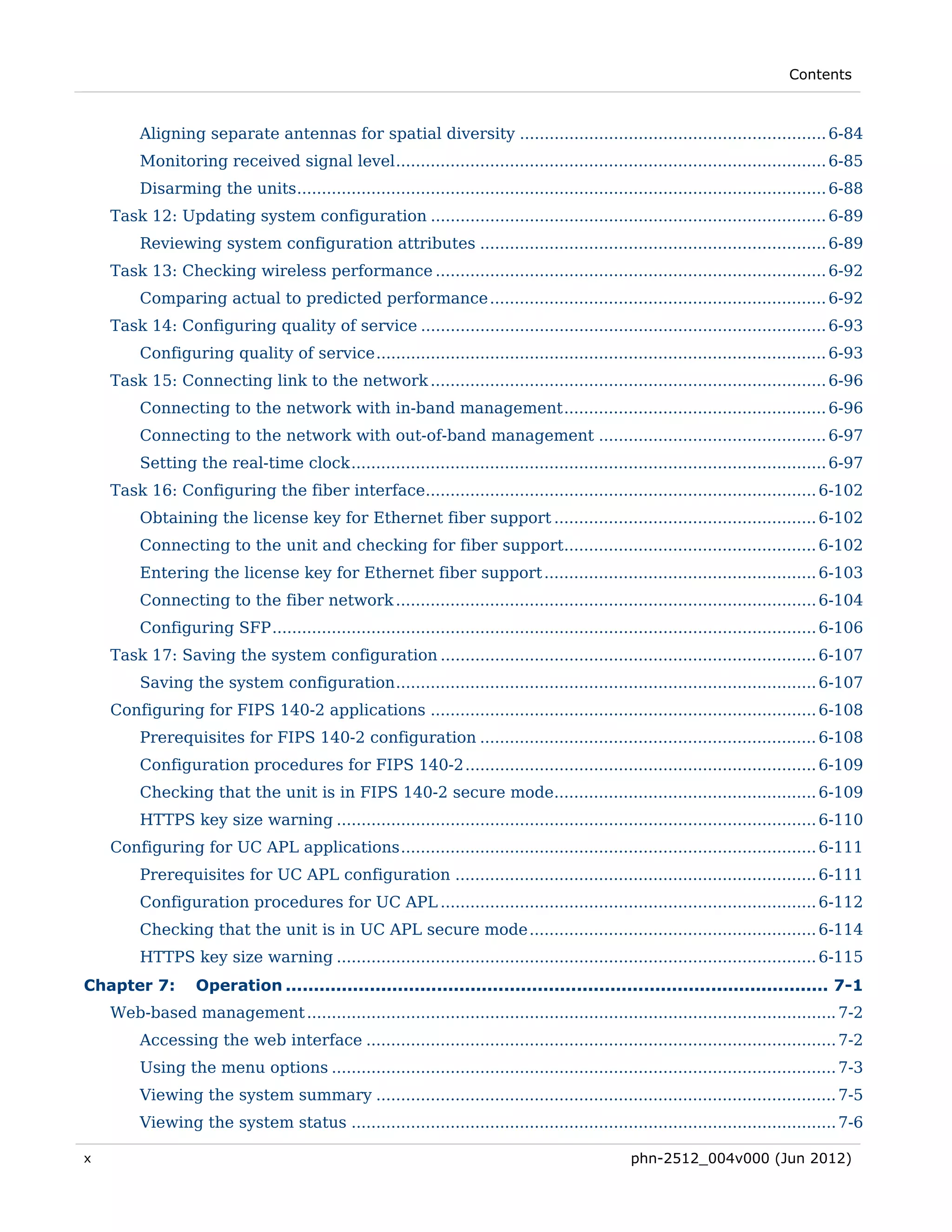
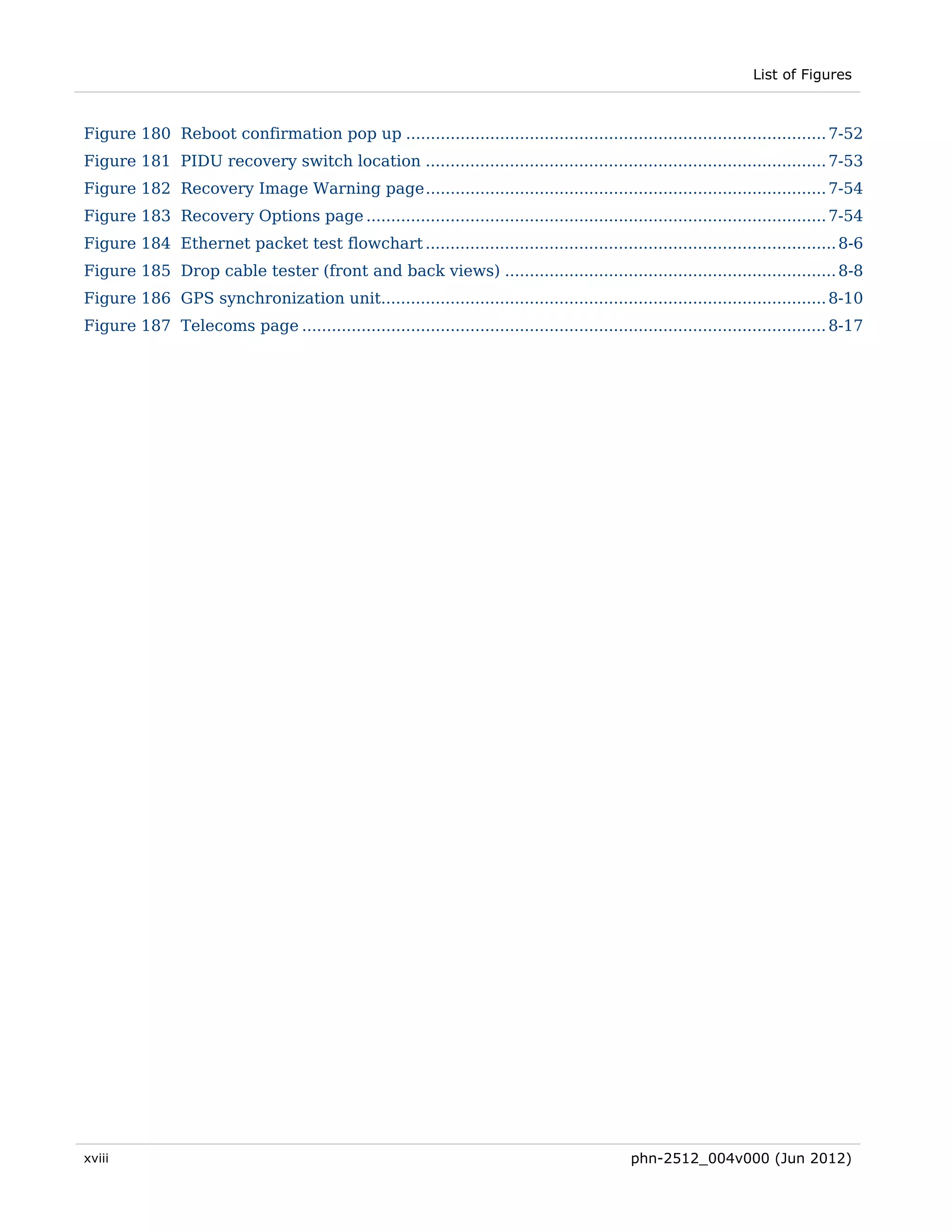
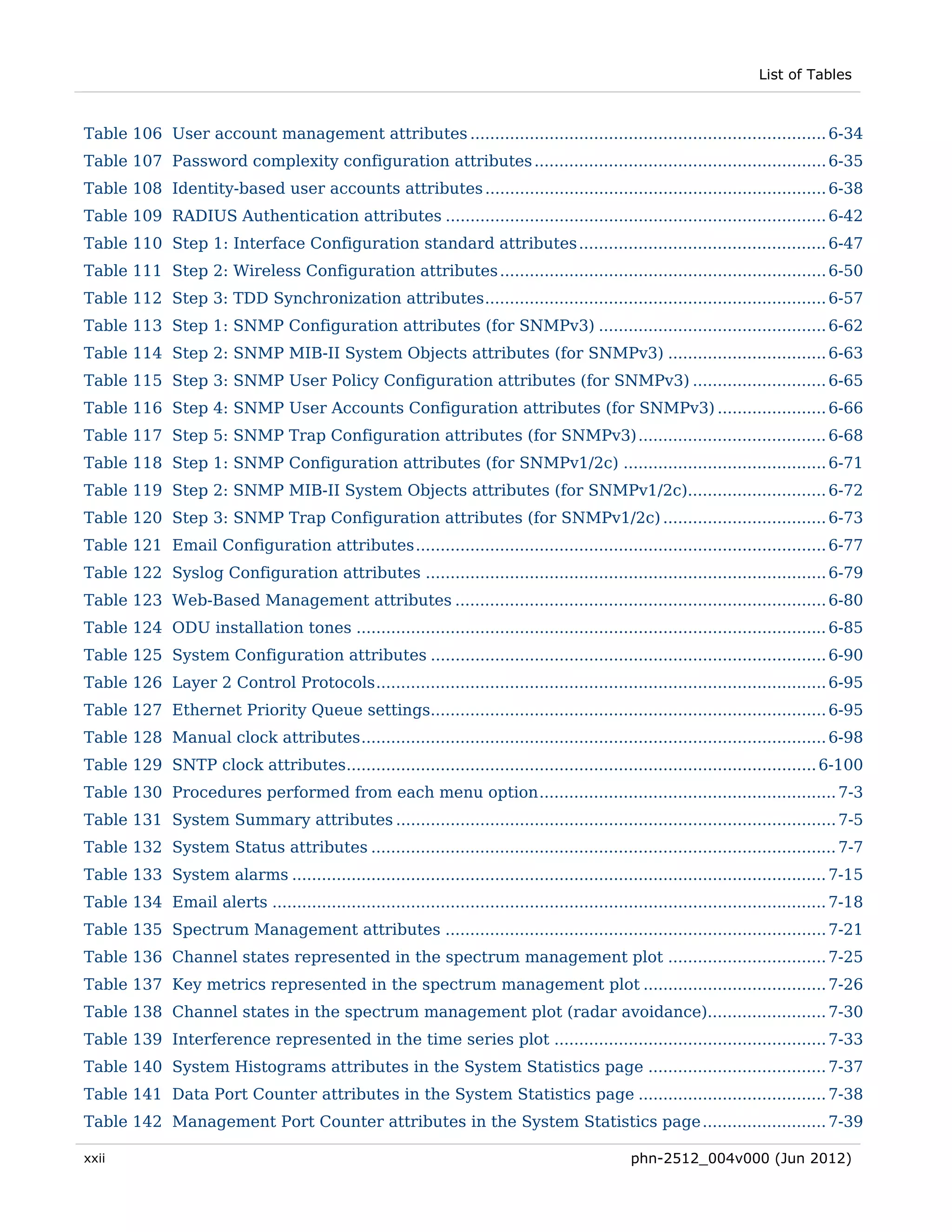
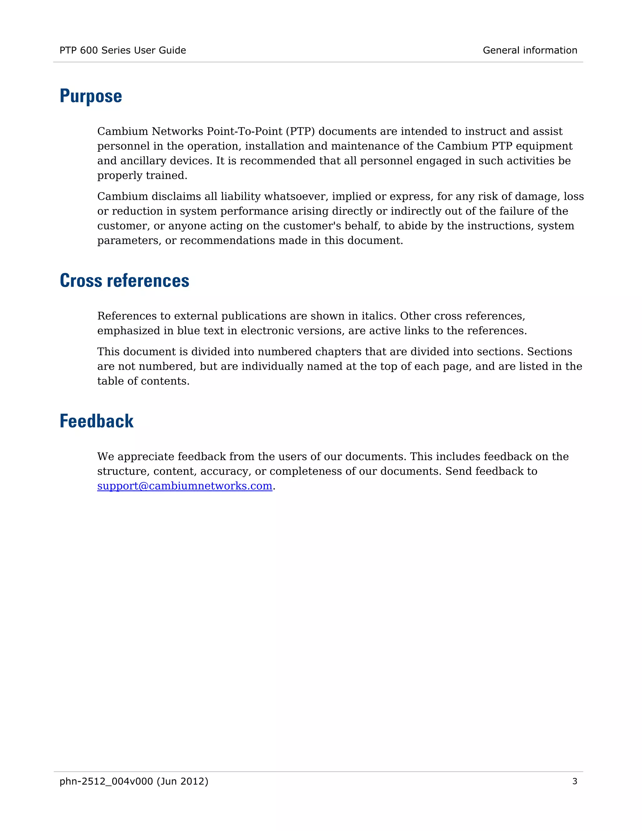
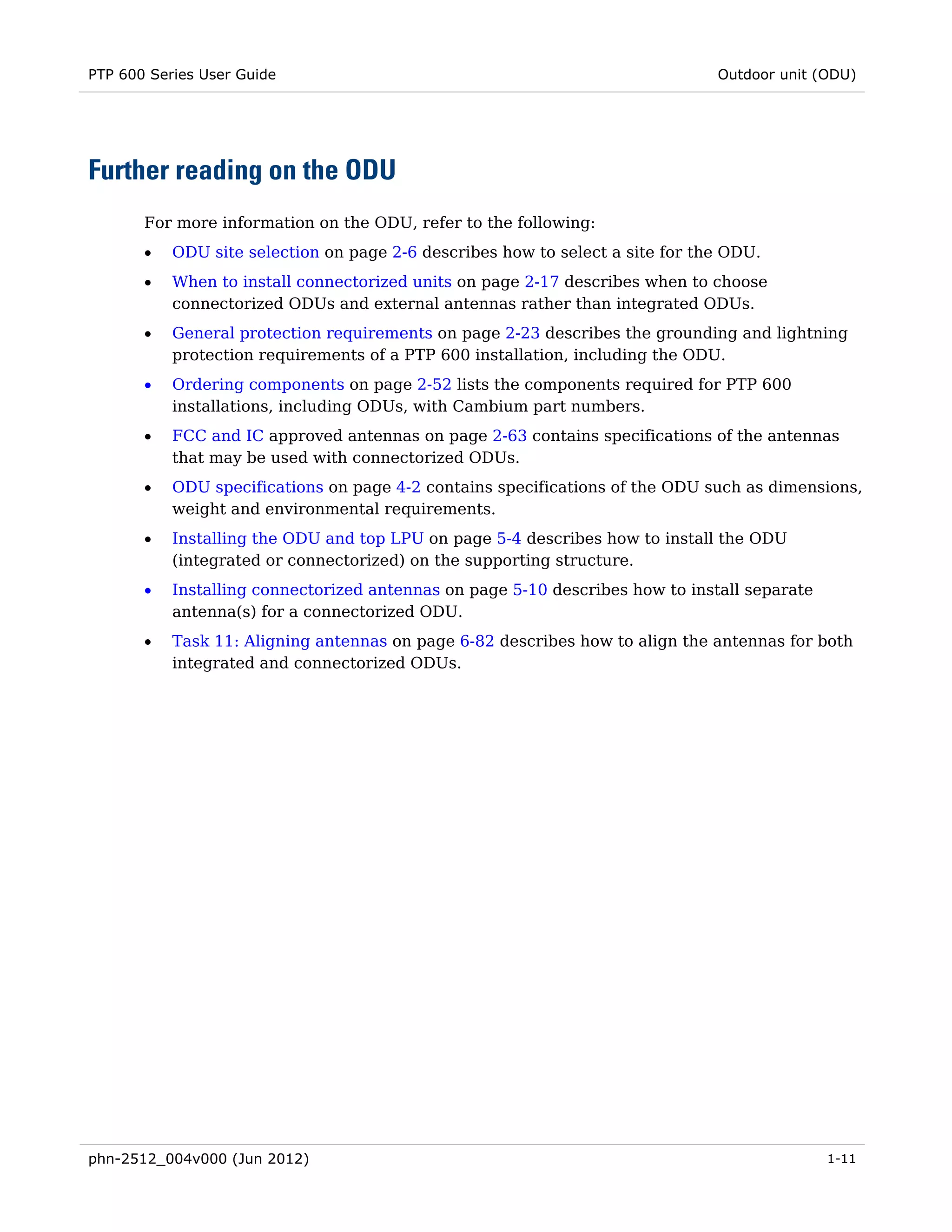
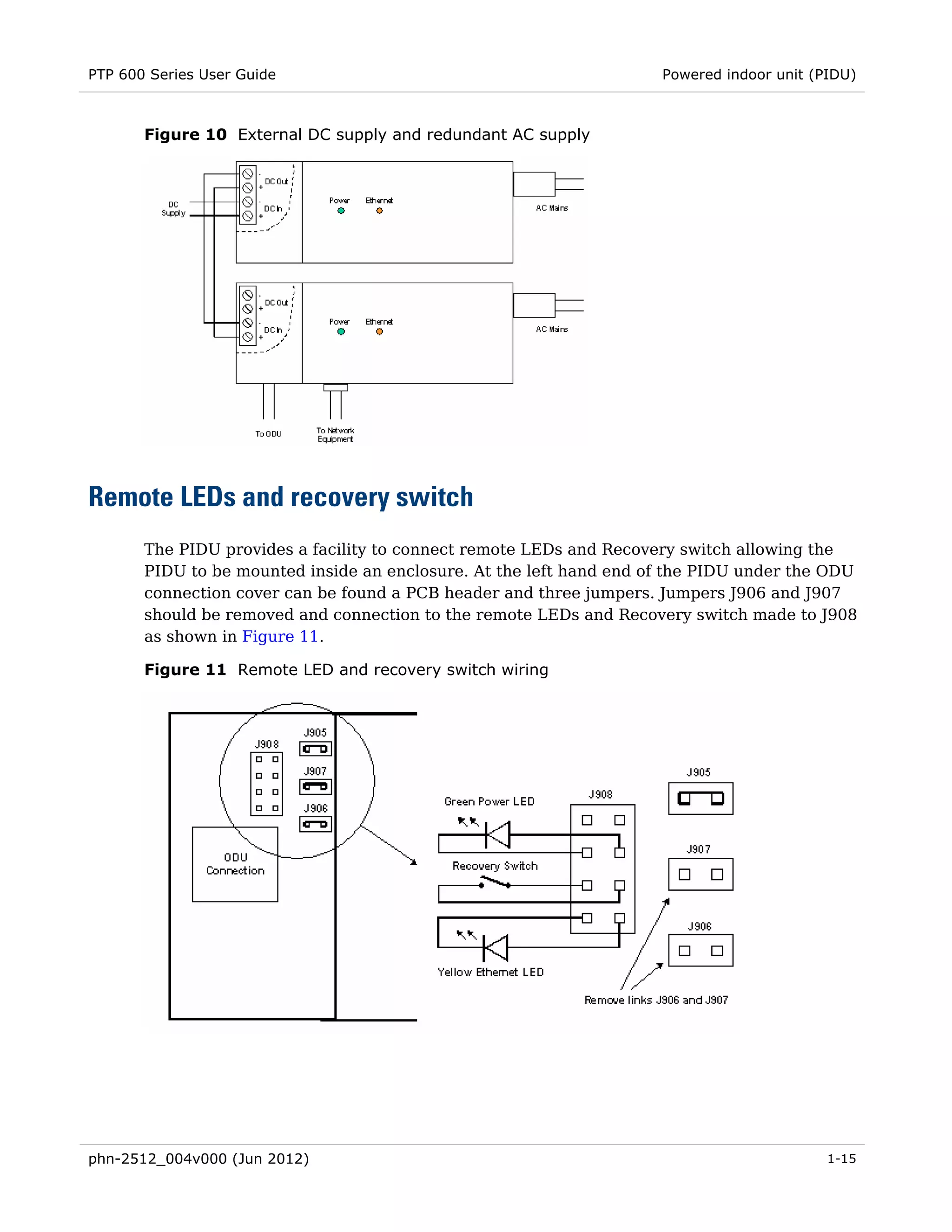
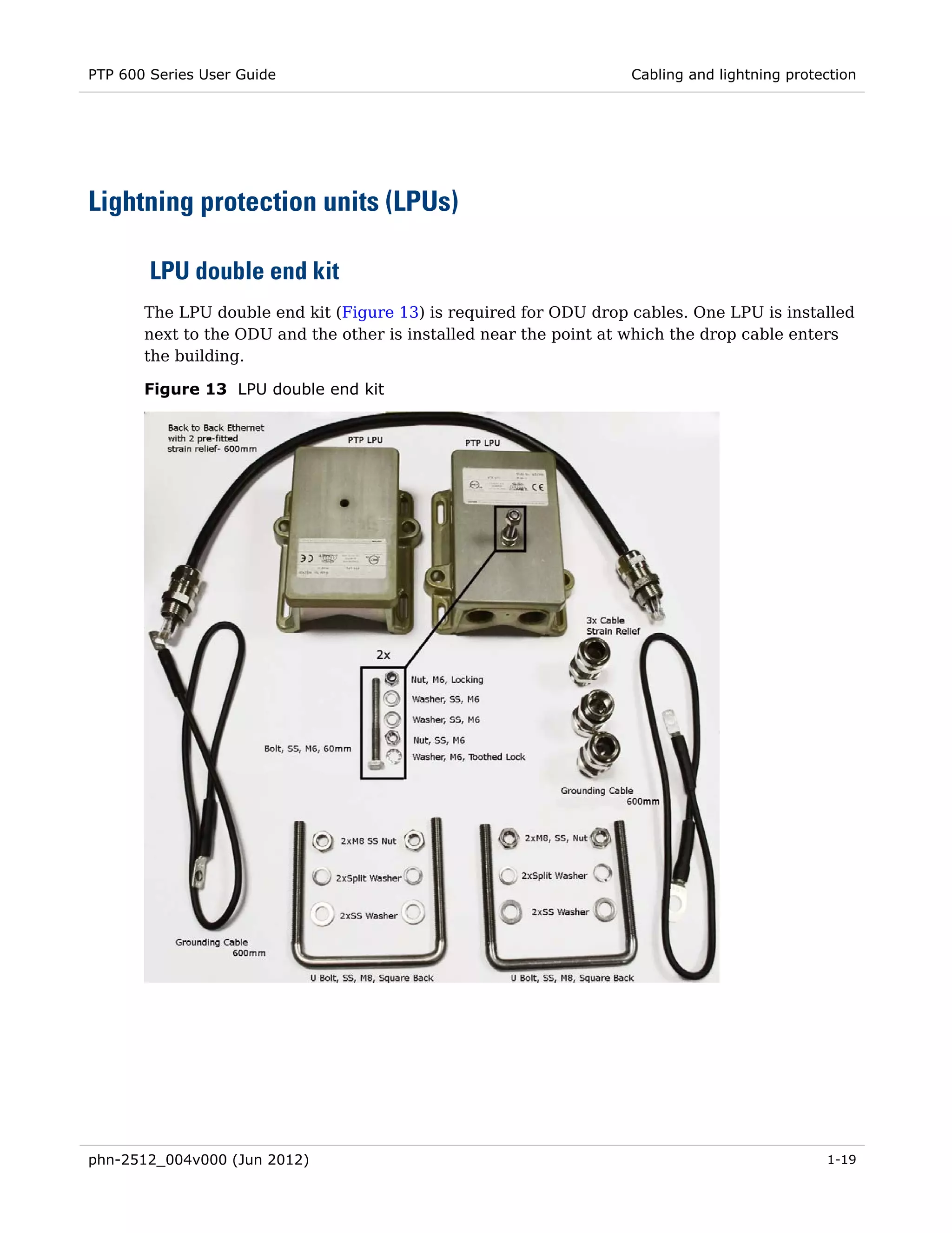
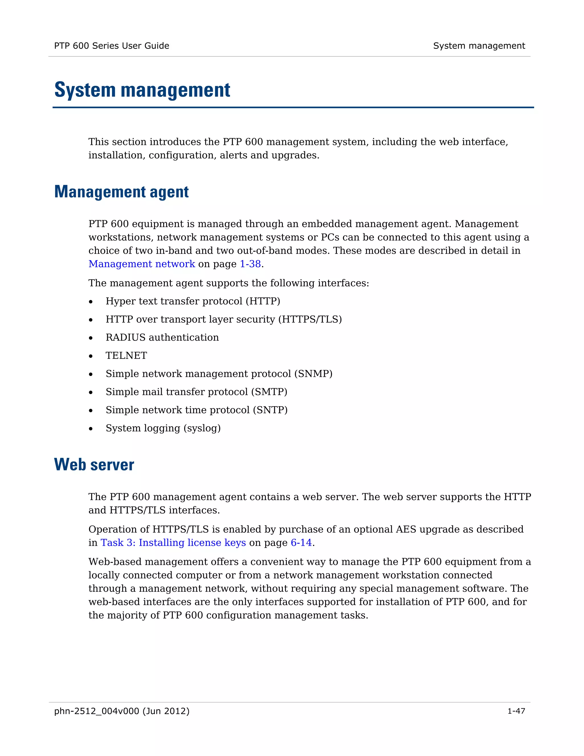
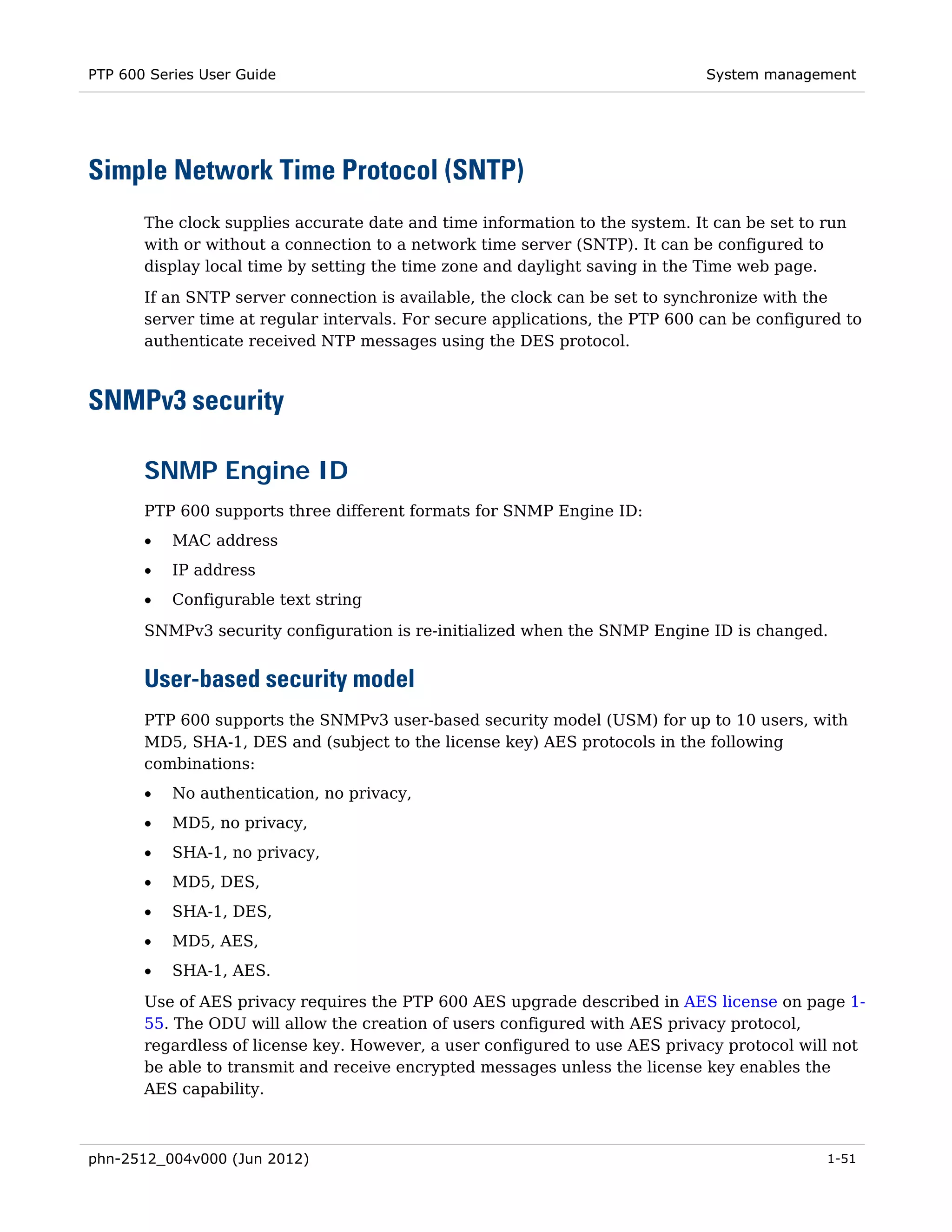
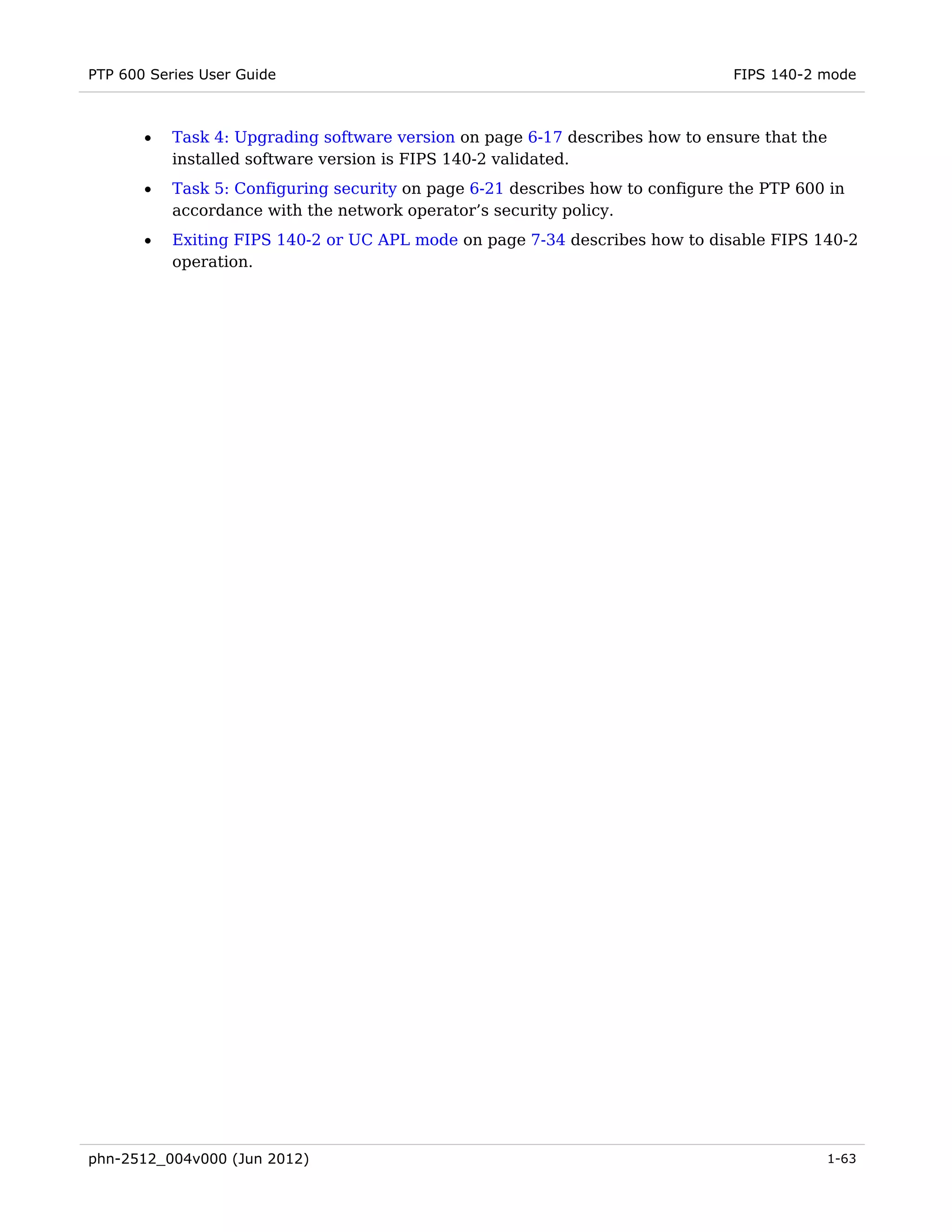
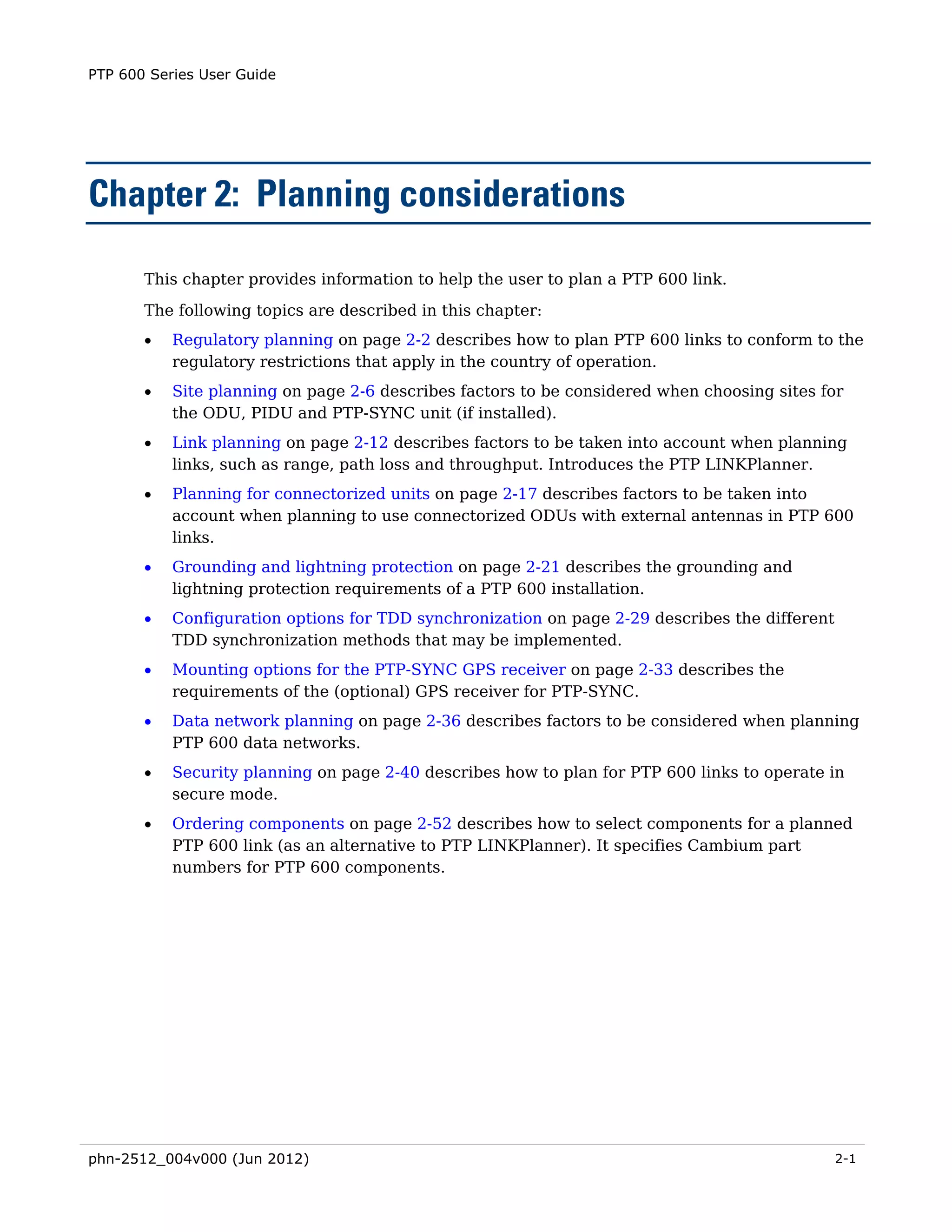
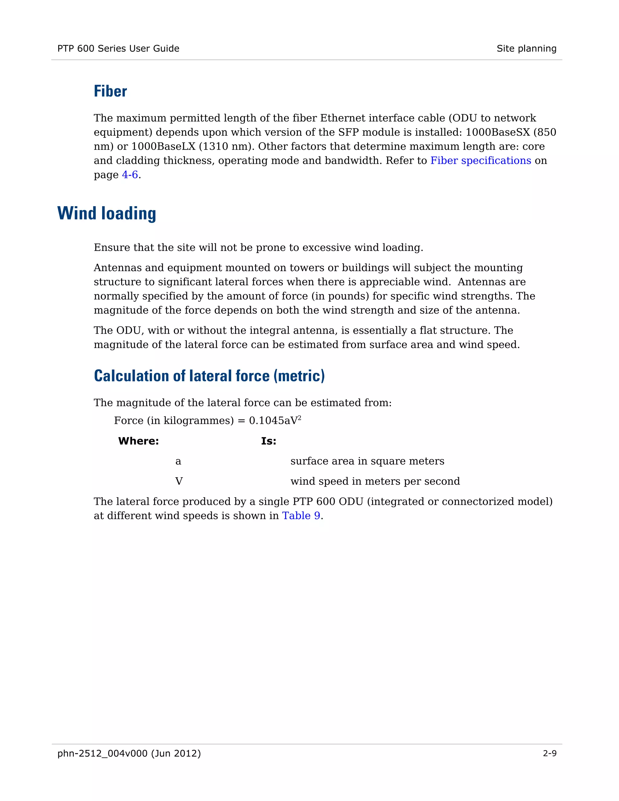
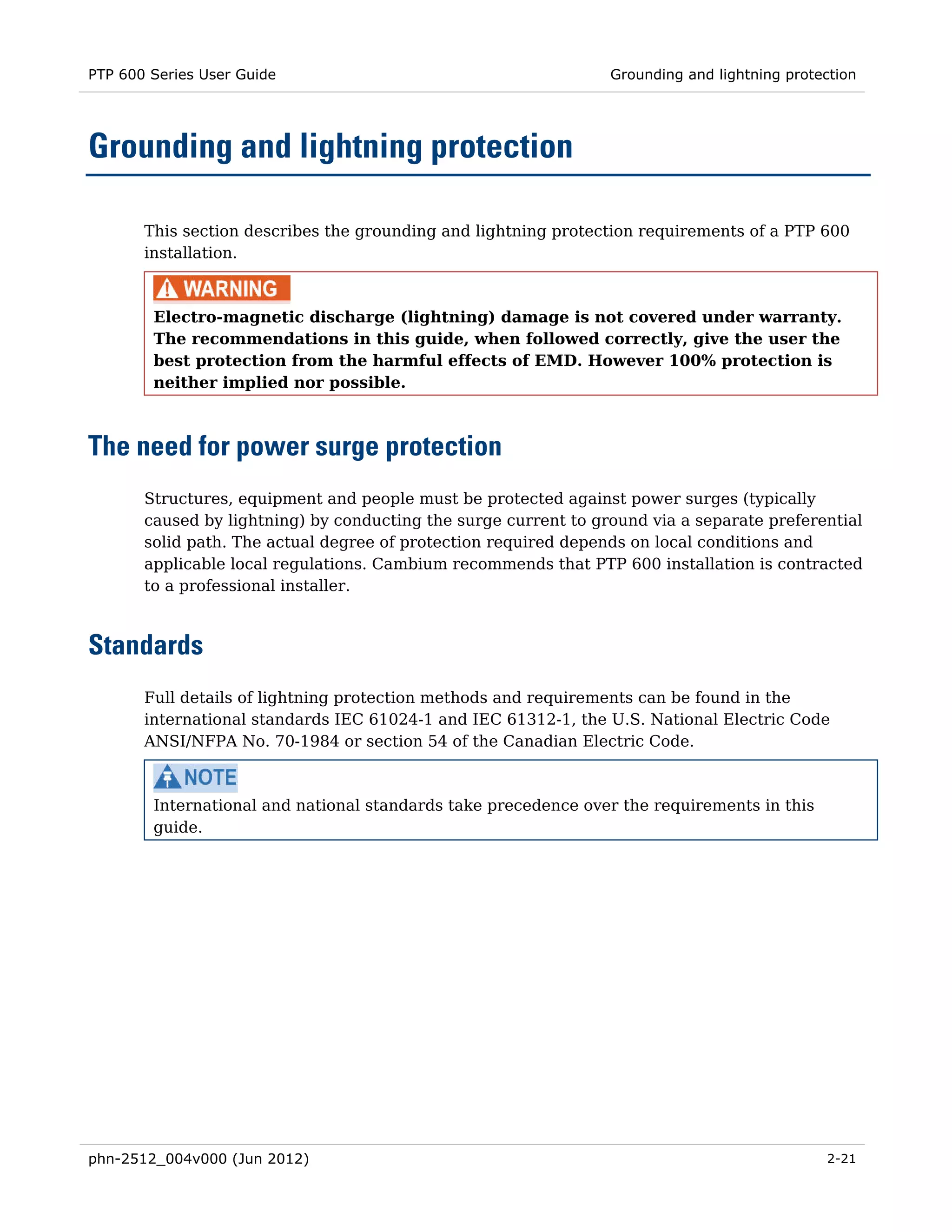
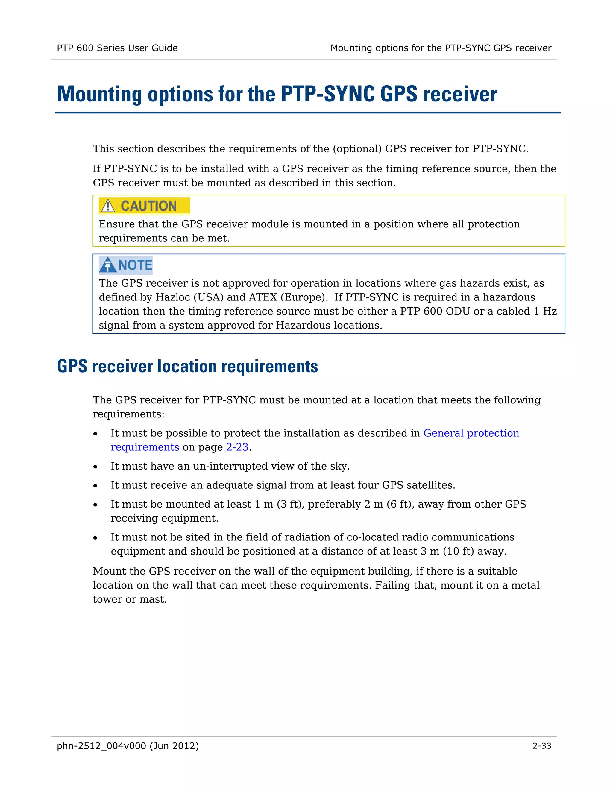
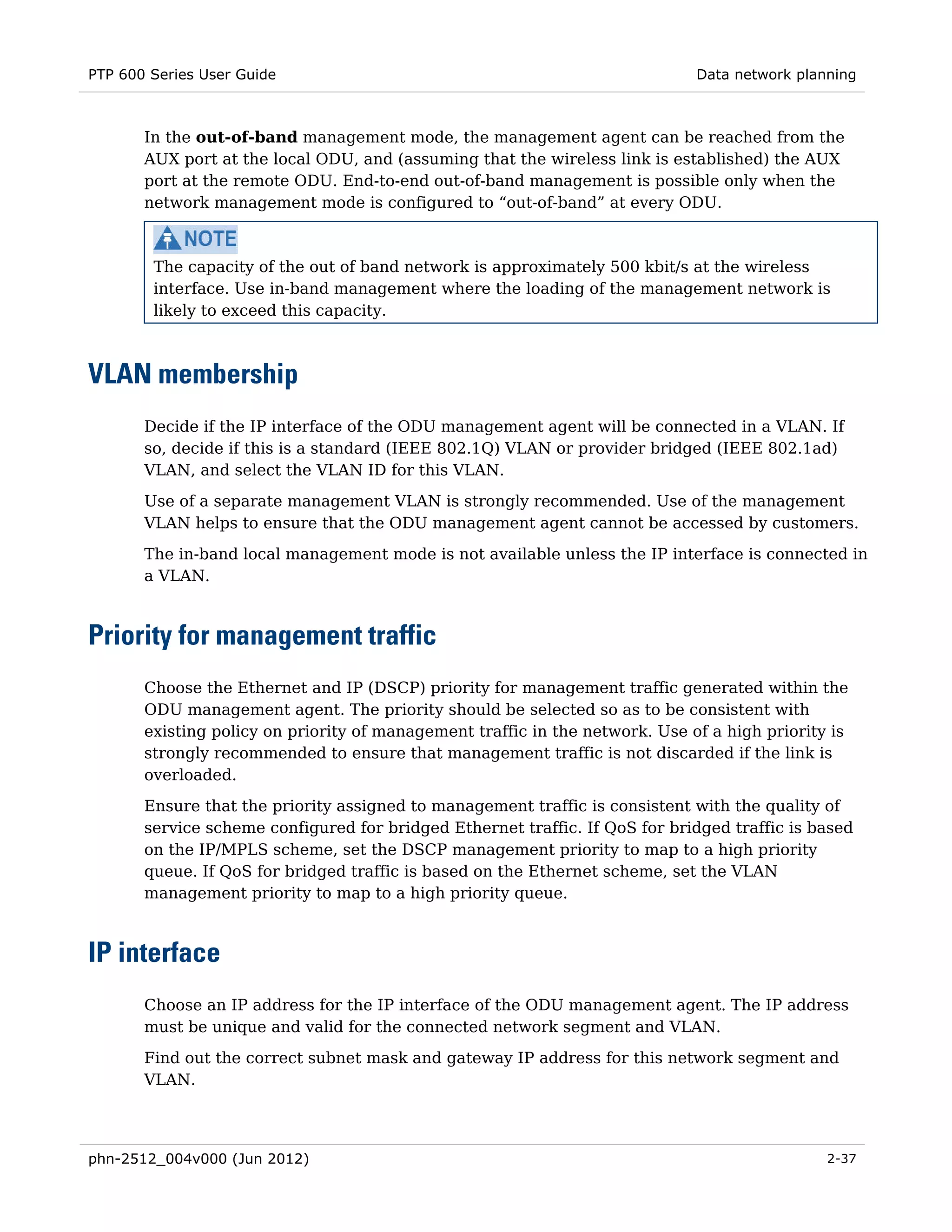
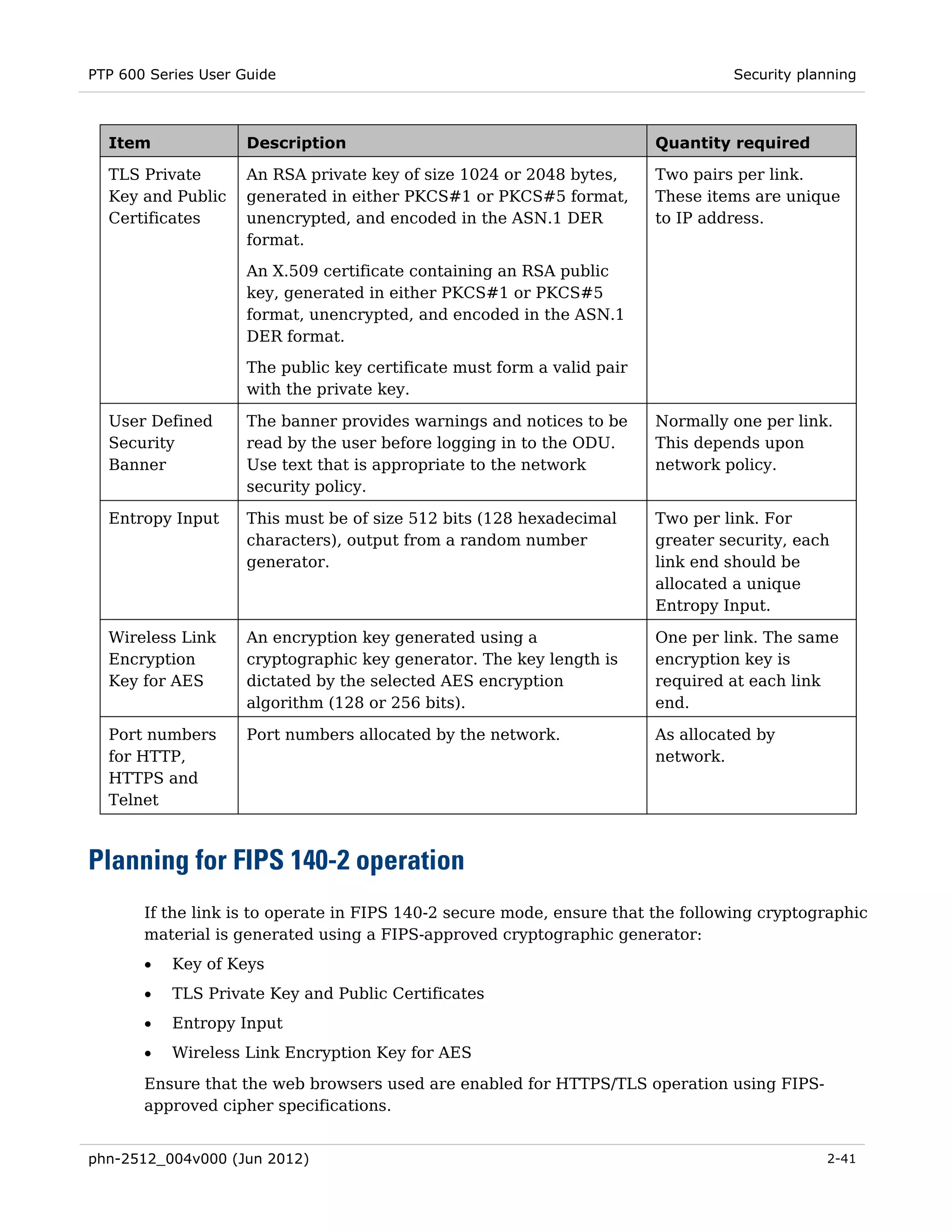
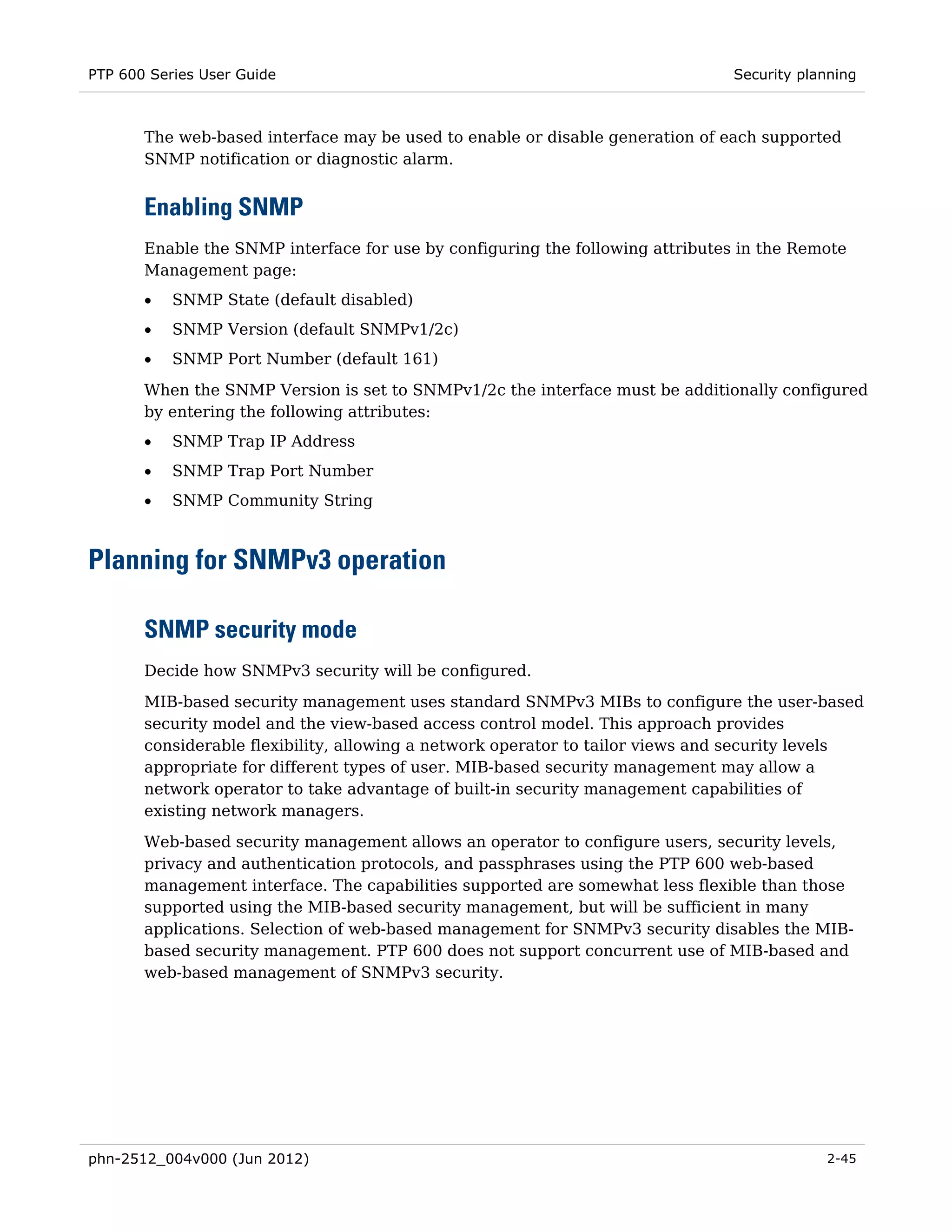
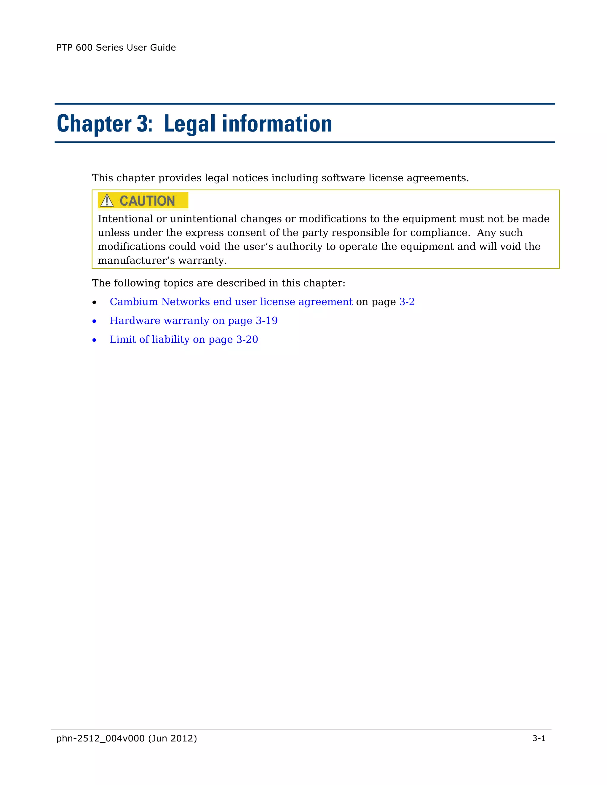
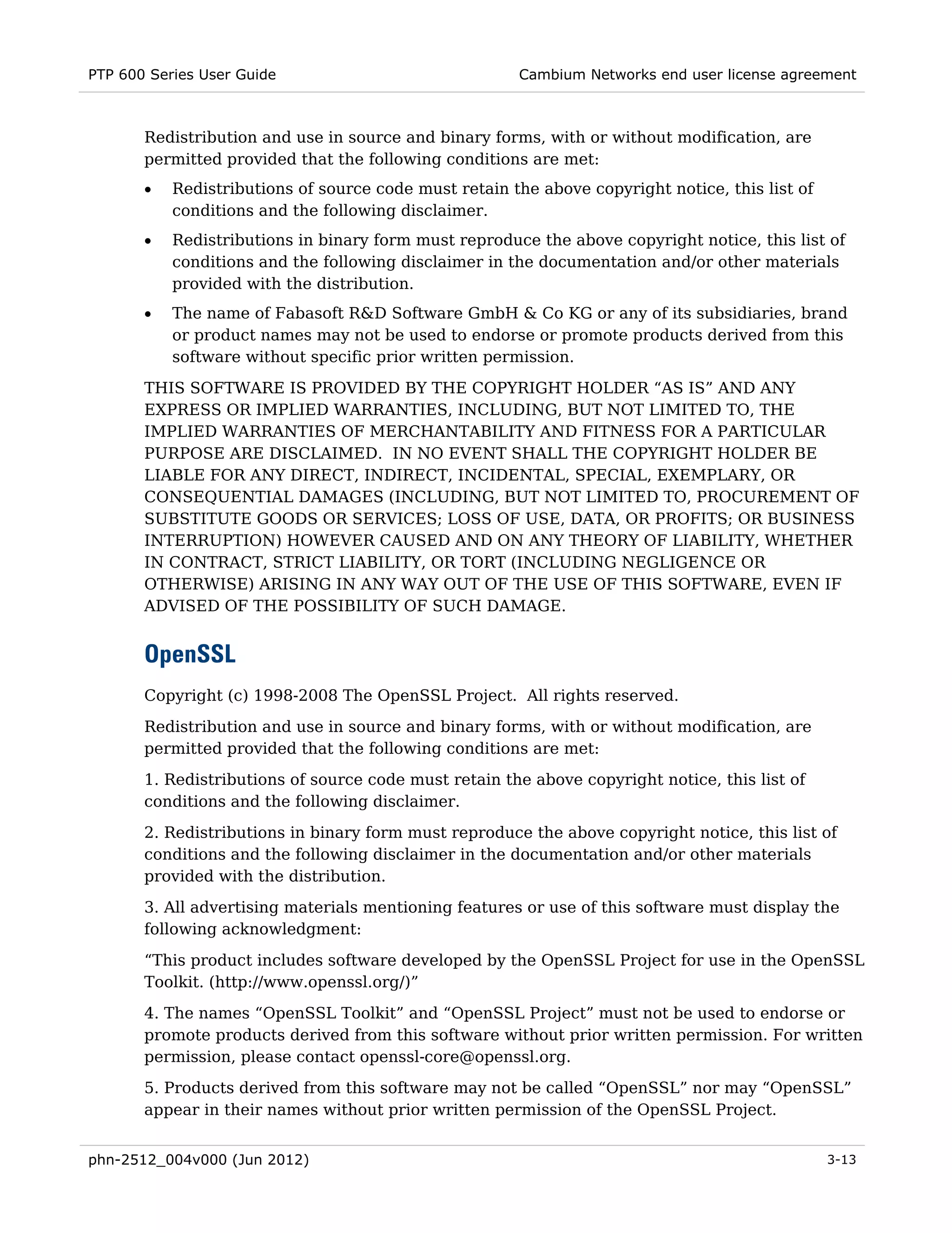
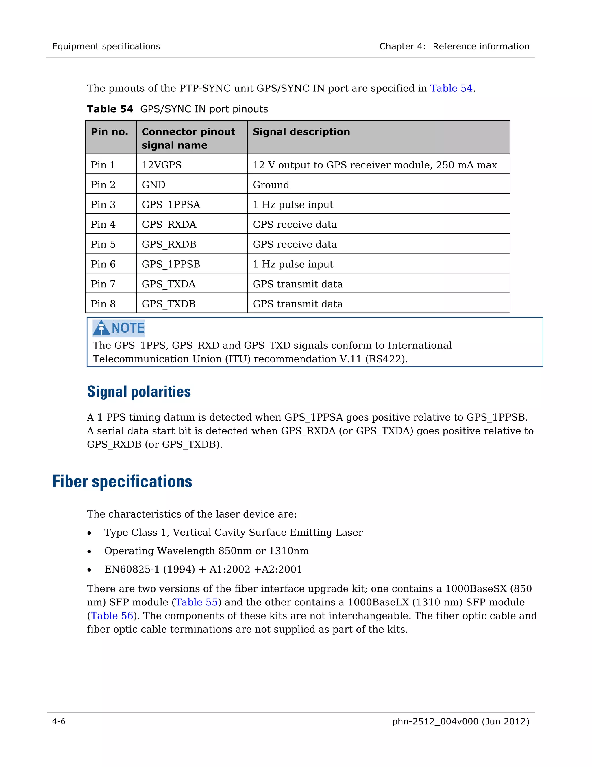
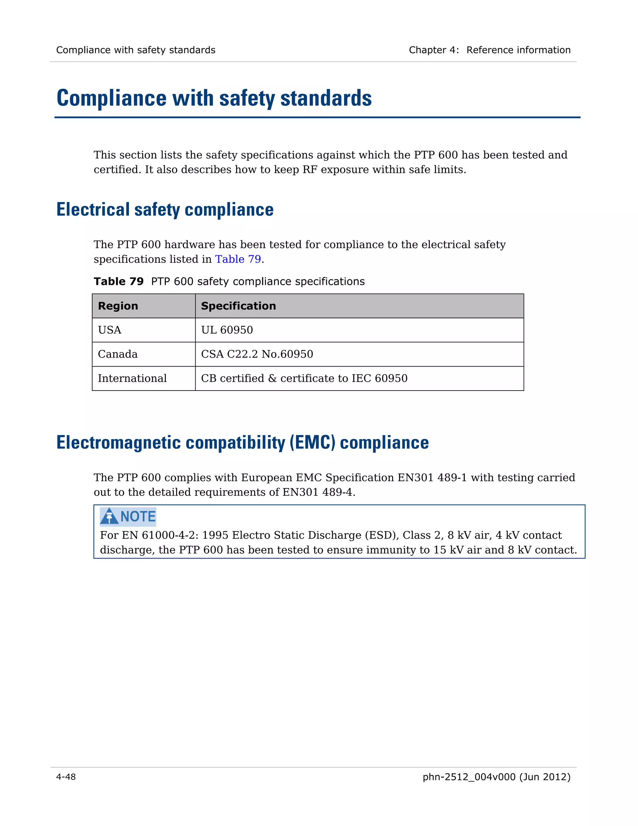
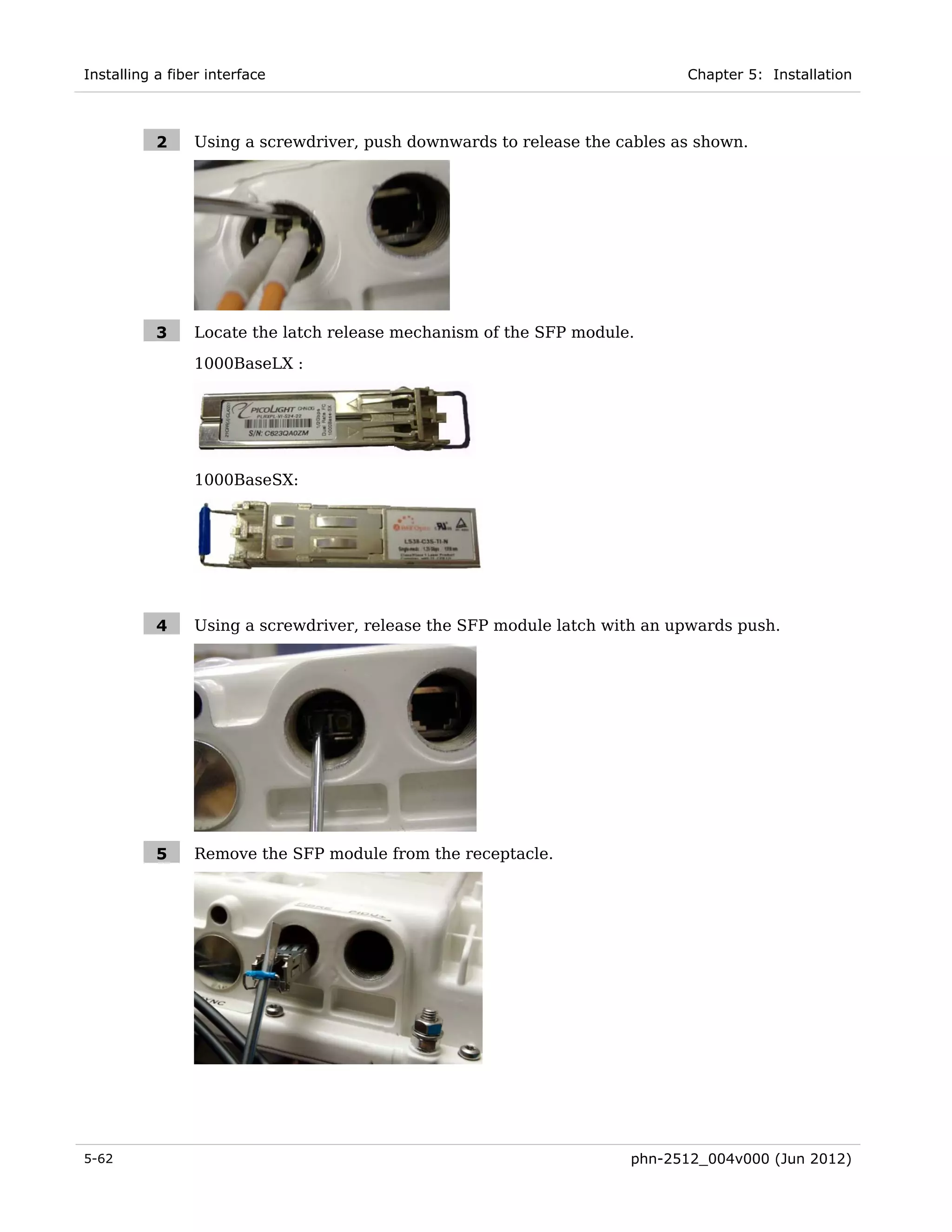
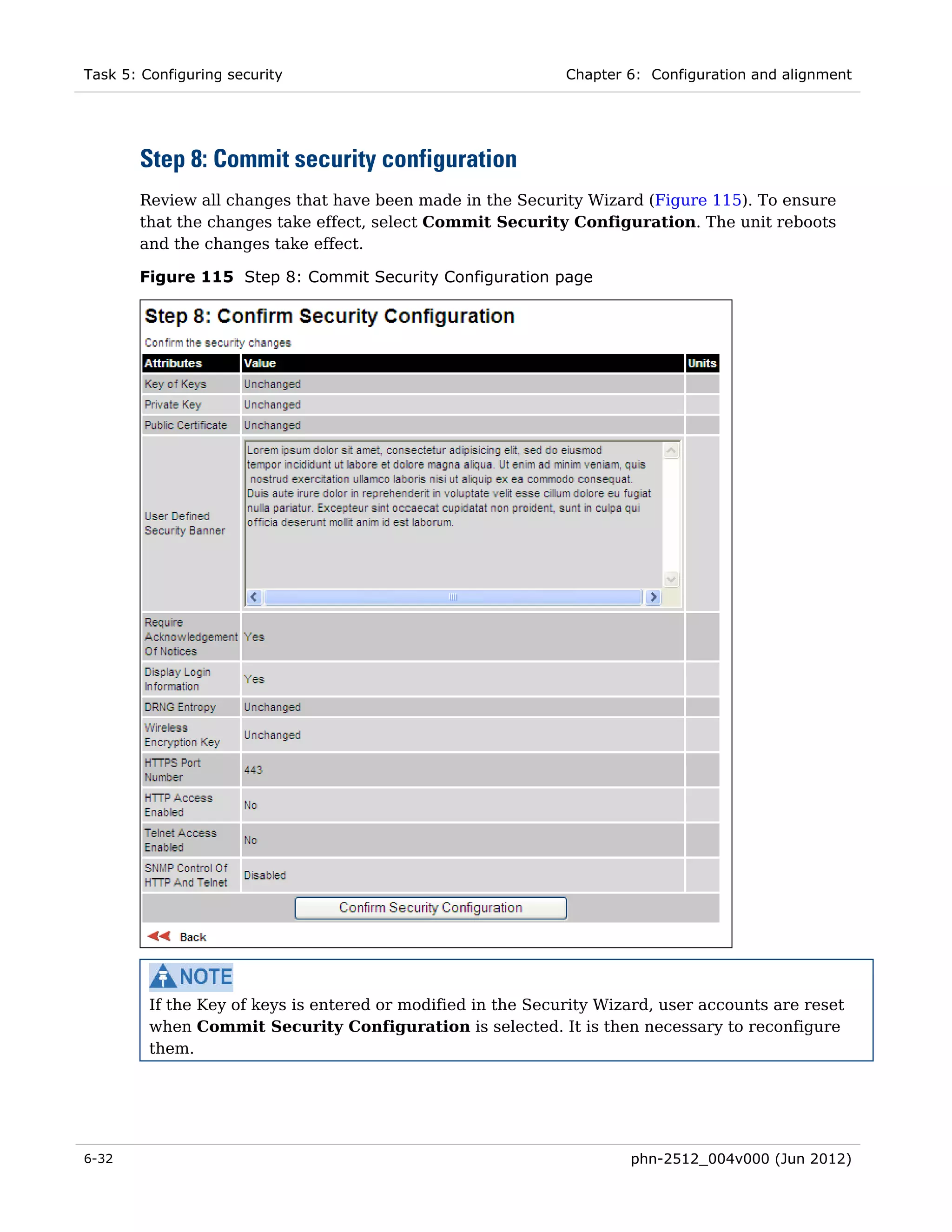
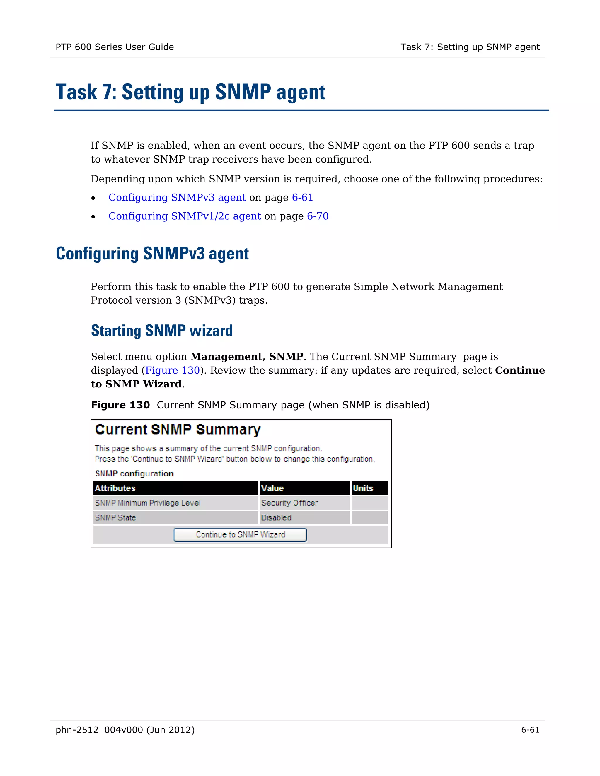
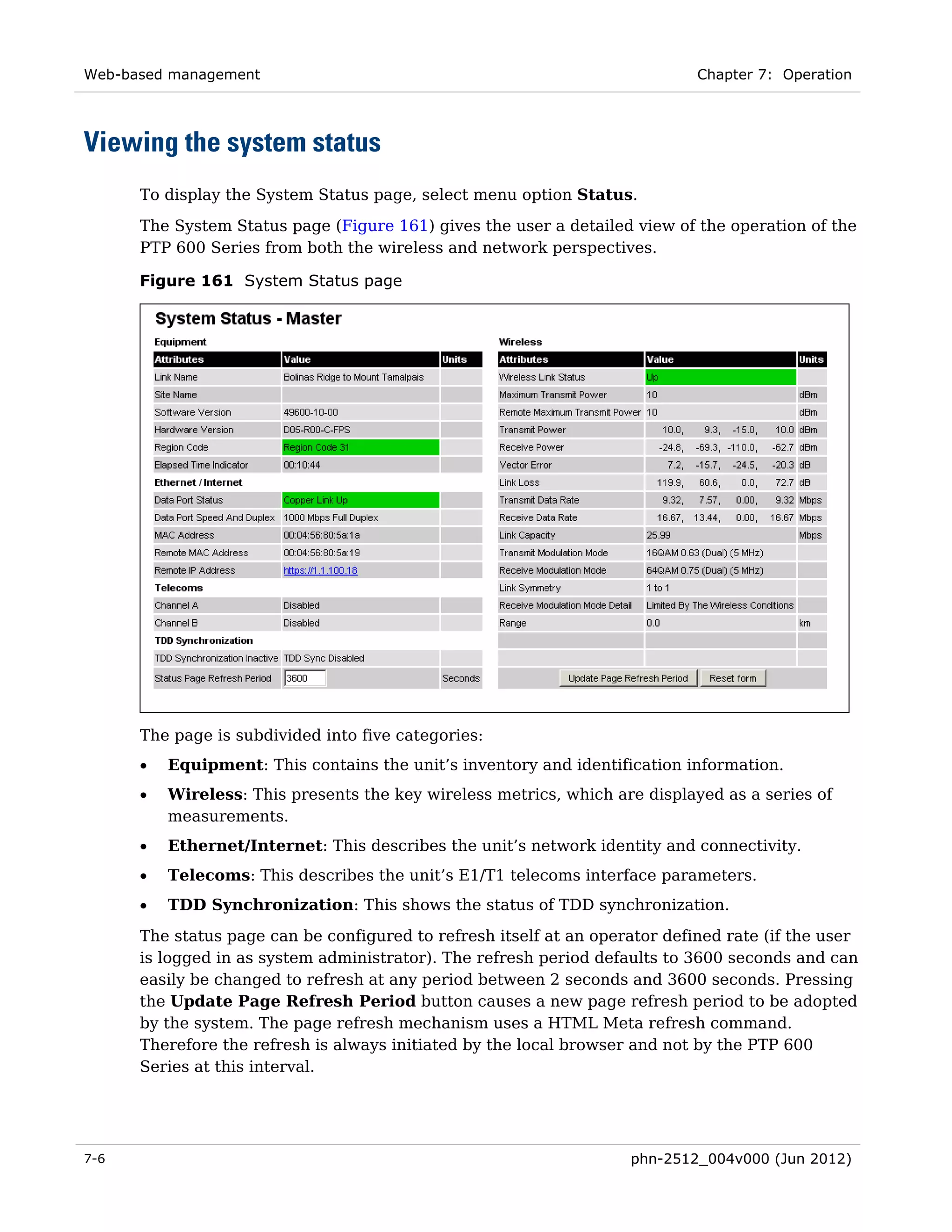
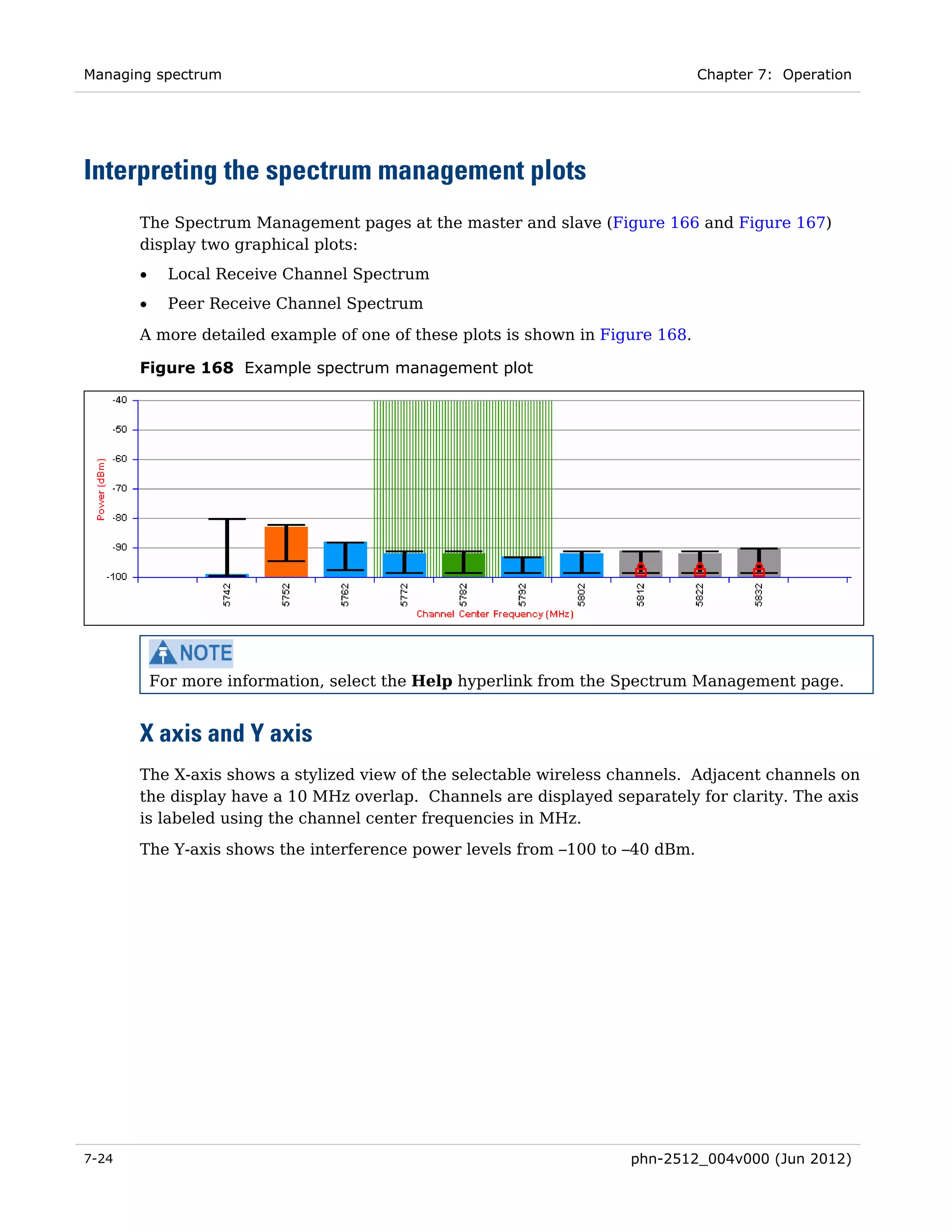
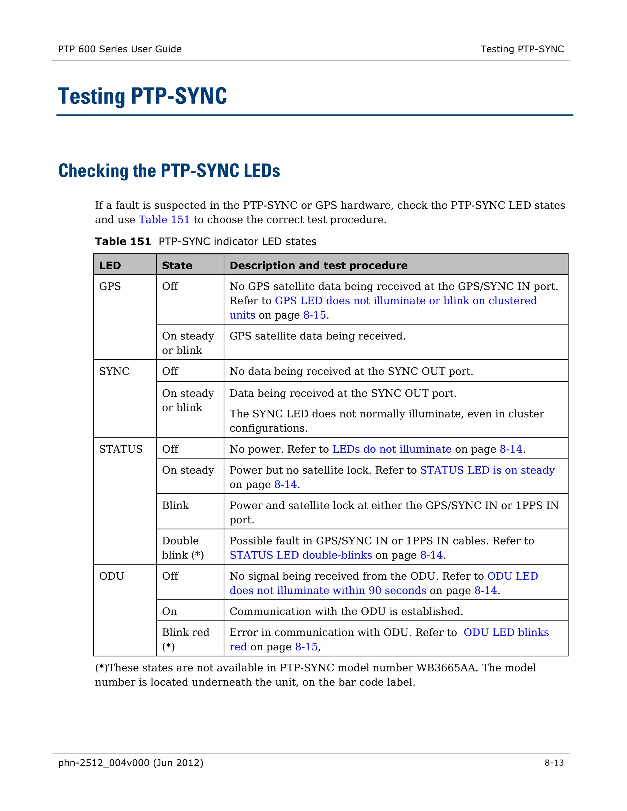
If authentication or authentication and privacy protocols are required, identify passphrases
for each protocol for each SNMP user. It is considered good practice to use different
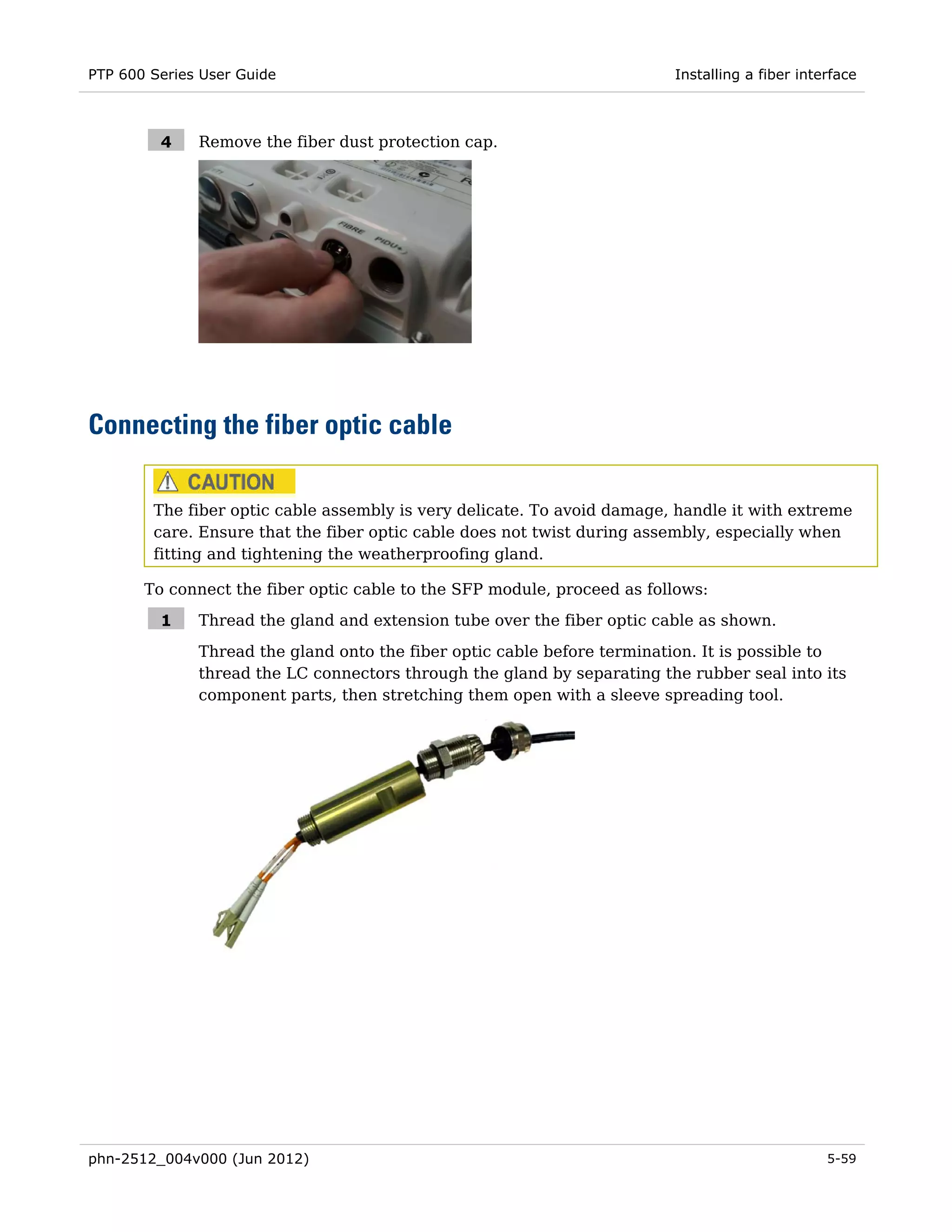
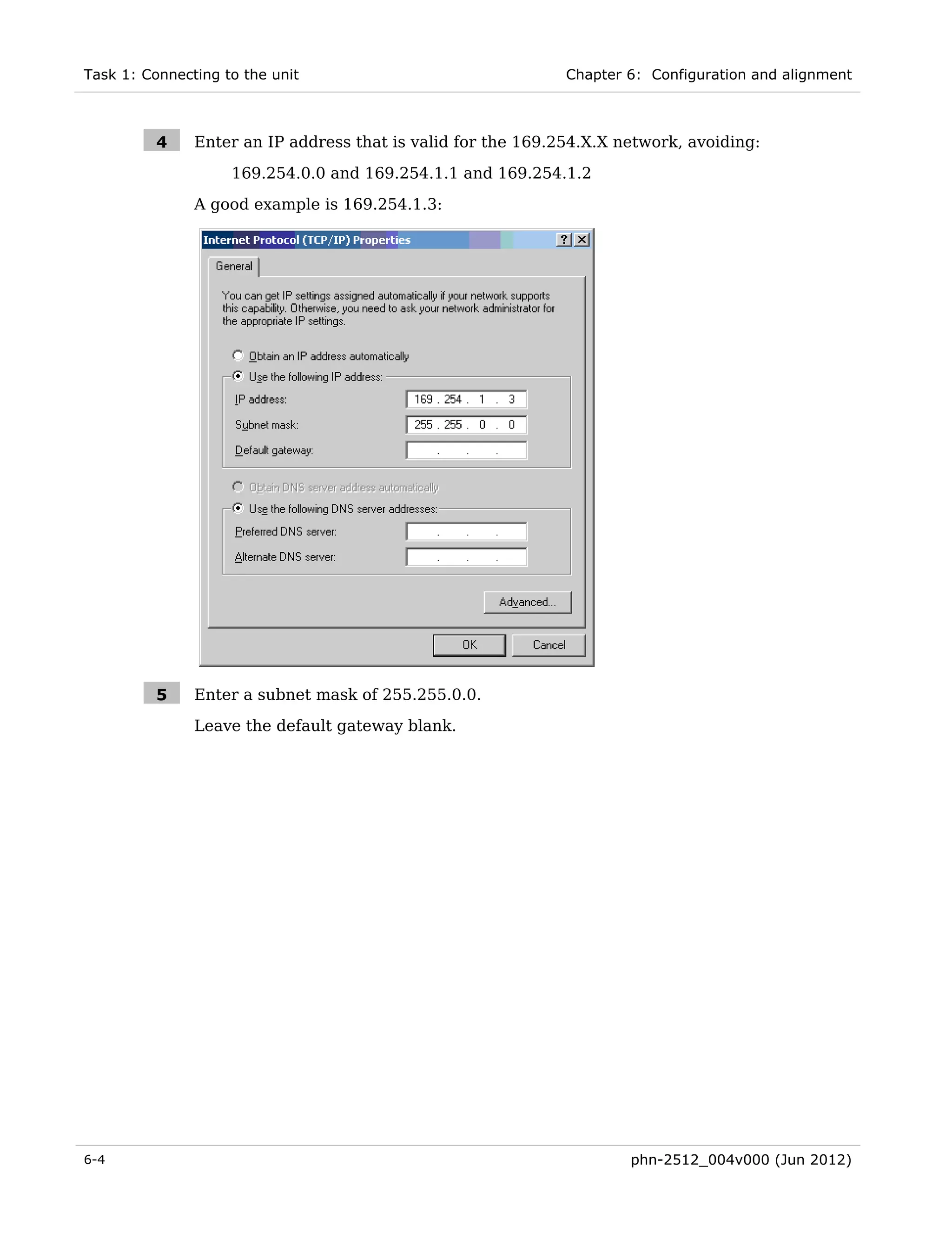
passphrases for authentication and privacy. Passphrases must have length between 8 and
32 characters, and may contain any of the characters listed in Table 17.
Table 17 Permitted character set for SNMPv3 passphrases
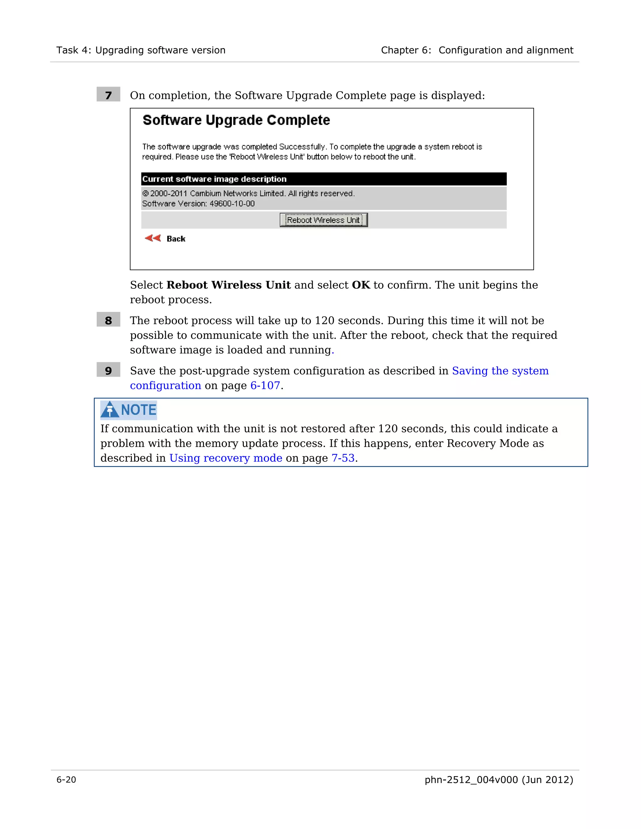
Character Code Character Code
<space> 32 ; 59
! 33 < 60
“ 34 = 61
# 35 > 62
$ 36 ? 63
% 37 @ 64
& 38 A..Z 65..90
' 39 [ 91
( 40 92
) 41 ] 93
* 42 ^ 94
+ 43 _ 95
, 44 ` 96
- 45 a..z 97..122
. 46 { 123
/ 47 | 124
0..9 48..57 } 125
: 58 ~ 126
Identify up to two SNMP users that will be configured to receive notifications (traps).
Identify the IP address and UDP port number of the associated SNMP manager.
phn-2512_004v000 (Jun 2012) 2-47](https://image.slidesharecdn.com/ptp600userguidesystemrelease10-03-120727061124-phpapp01/75/Ptp600-user-guide-system-release-10-03-153-2048.jpg)

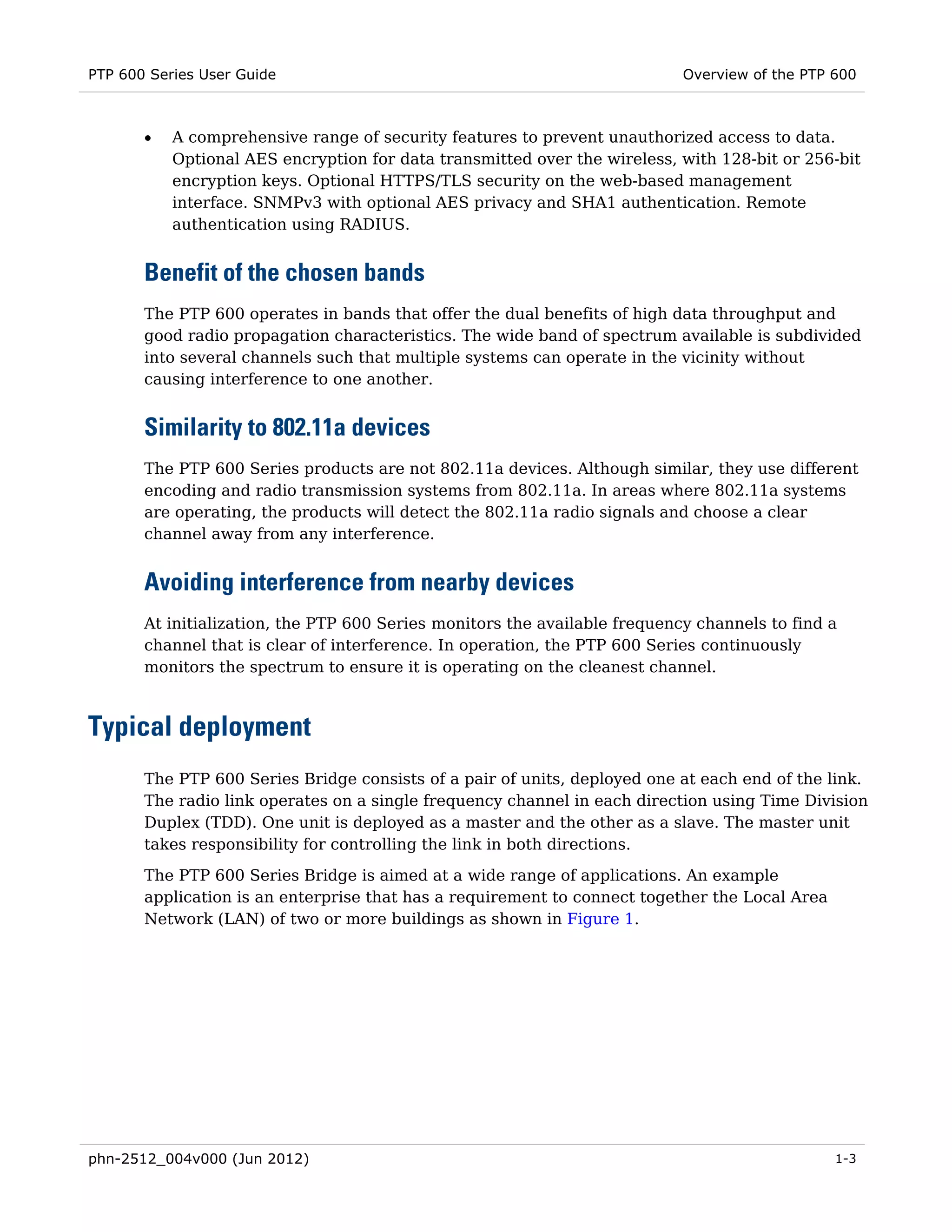
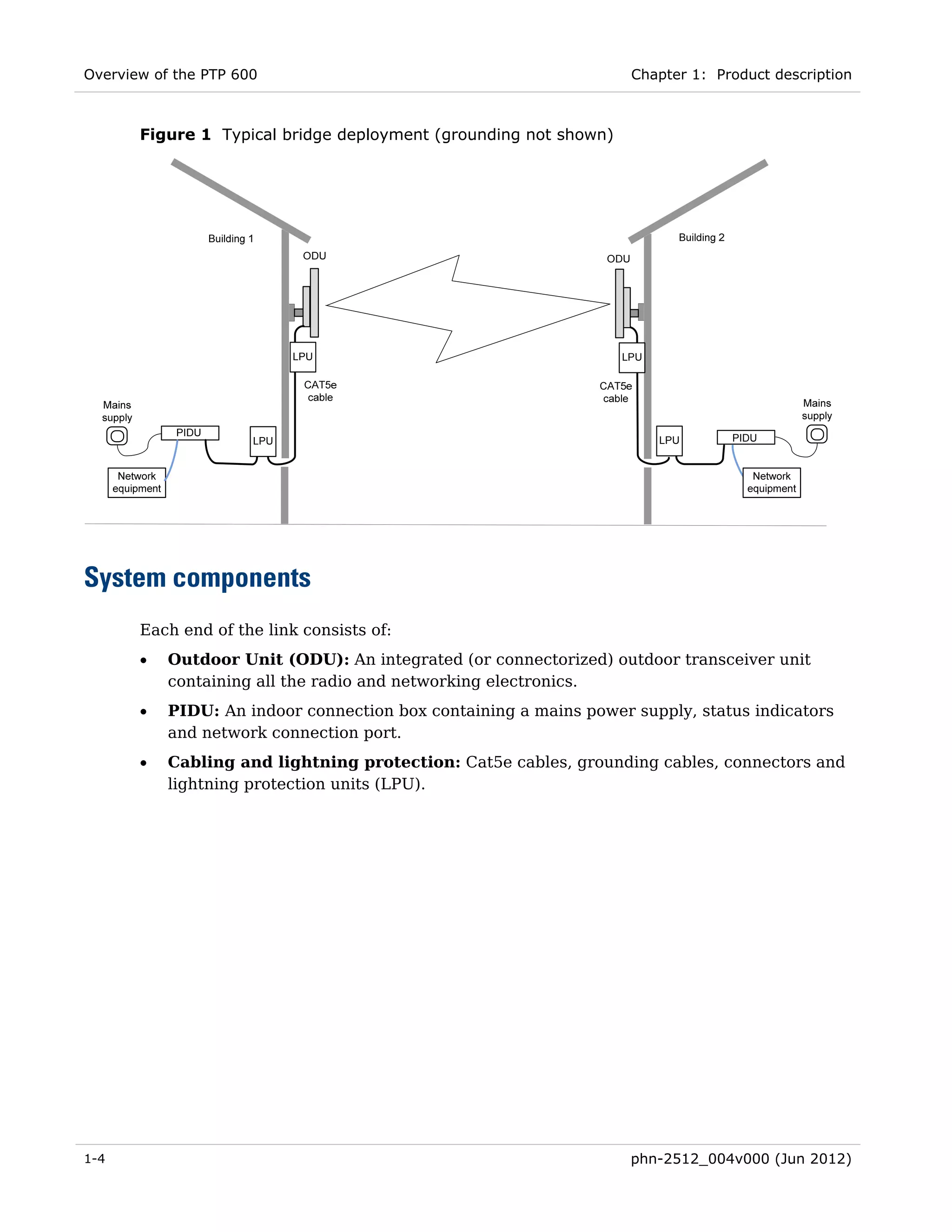
![PTP 600 Series User Guide Cambium Networks end user license agreement
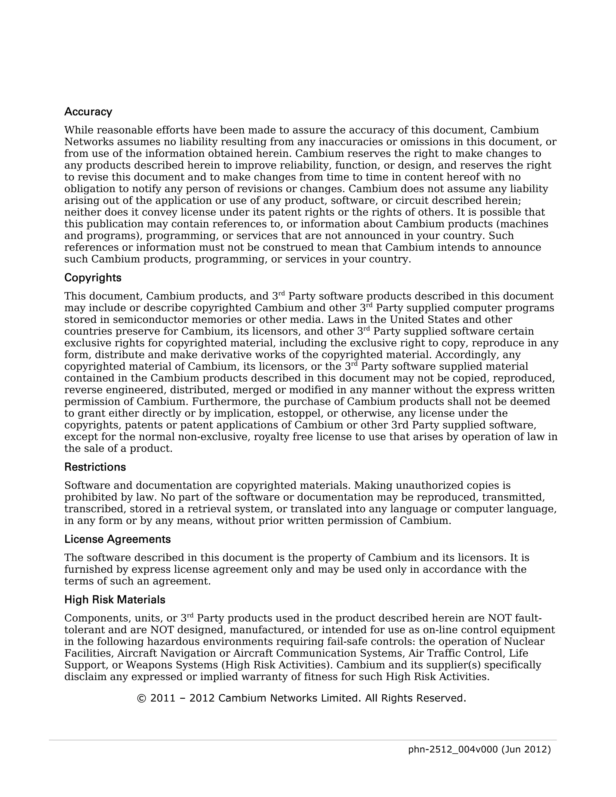
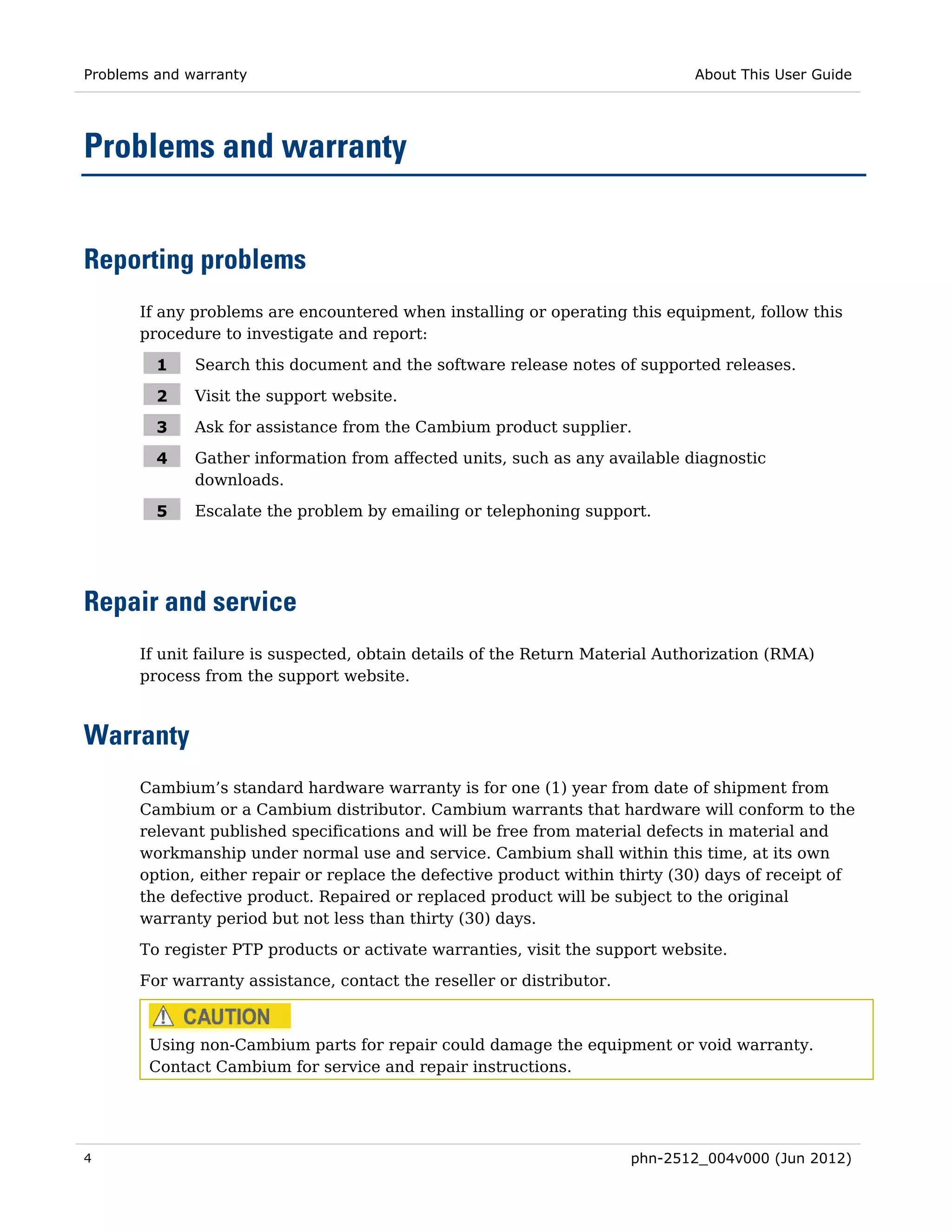
3. All advertising materials mentioning features or use of this software must display the
following acknowledgement:
“This product includes cryptographic software written by Eric Young (eay@cryptsoft.com)”
The word ‘cryptographic’ can be left out if the routines from the library being used are not
cryptographic related.
4. If you include any Windows specific code (or a derivative thereof) from the apps
directory (application code) you must include an acknowledgement:
“This product includes software written by Tim Hudson (tjh@cryptsoft.com)”
THIS SOFTWARE IS PROVIDED BY ERIC YOUNG “AS IS” AND ANY EXPRESS OR
IMPLIED WARRANTIES, INCLUDING, BUT NOT LIMITED TO, THE IMPLIED
WARRANTIES OF MERCHANTABILITY AND FITNESS FOR A PARTICULAR PURPOSE
ARE DISCLAIMED. IN NO EVENT SHALL THE AUTHOR OR CONTRIBUTORS BE LIABLE
FOR ANY DIRECT, INDIRECT, INCIDENTAL, SPECIAL, EXEMPLARY, OR
CONSEQUENTIAL DAMAGES (INCLUDING, BUT NOT LIMITED TO, PROCUREMENT OF
SUBSTITUTE GOODS OR SERVICES; LOSS OF USE, DATA, OR PROFITS; OR BUSINESS
INTERRUPTION) HOWEVER CAUSED AND ON ANY THEORY OF LIABILITY, WHETHER
IN CONTRACT, STRICT LIABILITY, OR TORT (INCLUDING NEGLIGENCE OR
OTHERWISE) ARISING IN ANY WAY OUT OF THE USE OF THIS SOFTWARE, EVEN IF
ADVISED OF THE POSSIBILITY OF SUCH DAMAGE.
The license and distribution terms for any publically available version or derivative of this
code cannot be changed. i.e. this code cannot simply be copied and put under another
distribution license [including the GNU Public License.]
Zlib
Copyright © 1995-2005 Jean-loup Gailly and Mark Adler
This software is provided ‘as-is’, without any express or implied warranty. In no event will
the authors be held liable for any damages arising from the use of this software.
Permission is granted to anyone to use this software for any purpose, including
commercial applications, and to alter it and redistribute it freely, subject to the following
restrictions:
1. The origin of this software must not be misrepresented; you must not claim that you
wrote the original software. If you use this software in a product, an acknowledgment in
the product documentation would be appreciated but is not required.
2. Altered source versions must be plainly marked as such, and must not be
misrepresented as being the original software.
3. This notice may not be removed or altered from any source distribution.
Jean-loup Gailly jloup@gzip.org
Mark Adler madler@alumni.caltech.edu
phn-2512_004v000 (Jun 2012) 3-15](https://image.slidesharecdn.com/ptp600userguidesystemrelease10-03-120727061124-phpapp01/75/Ptp600-user-guide-system-release-10-03-195-2048.jpg)


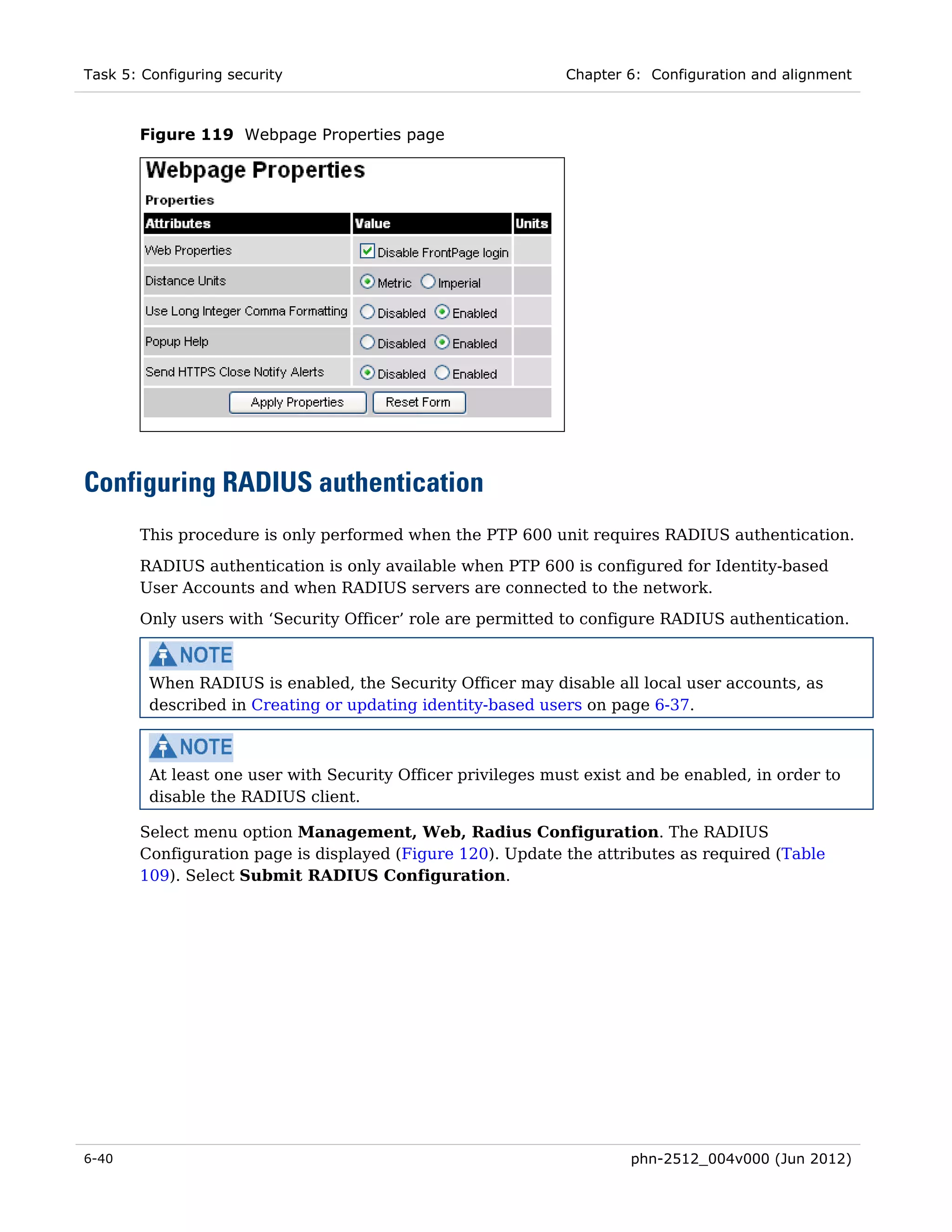
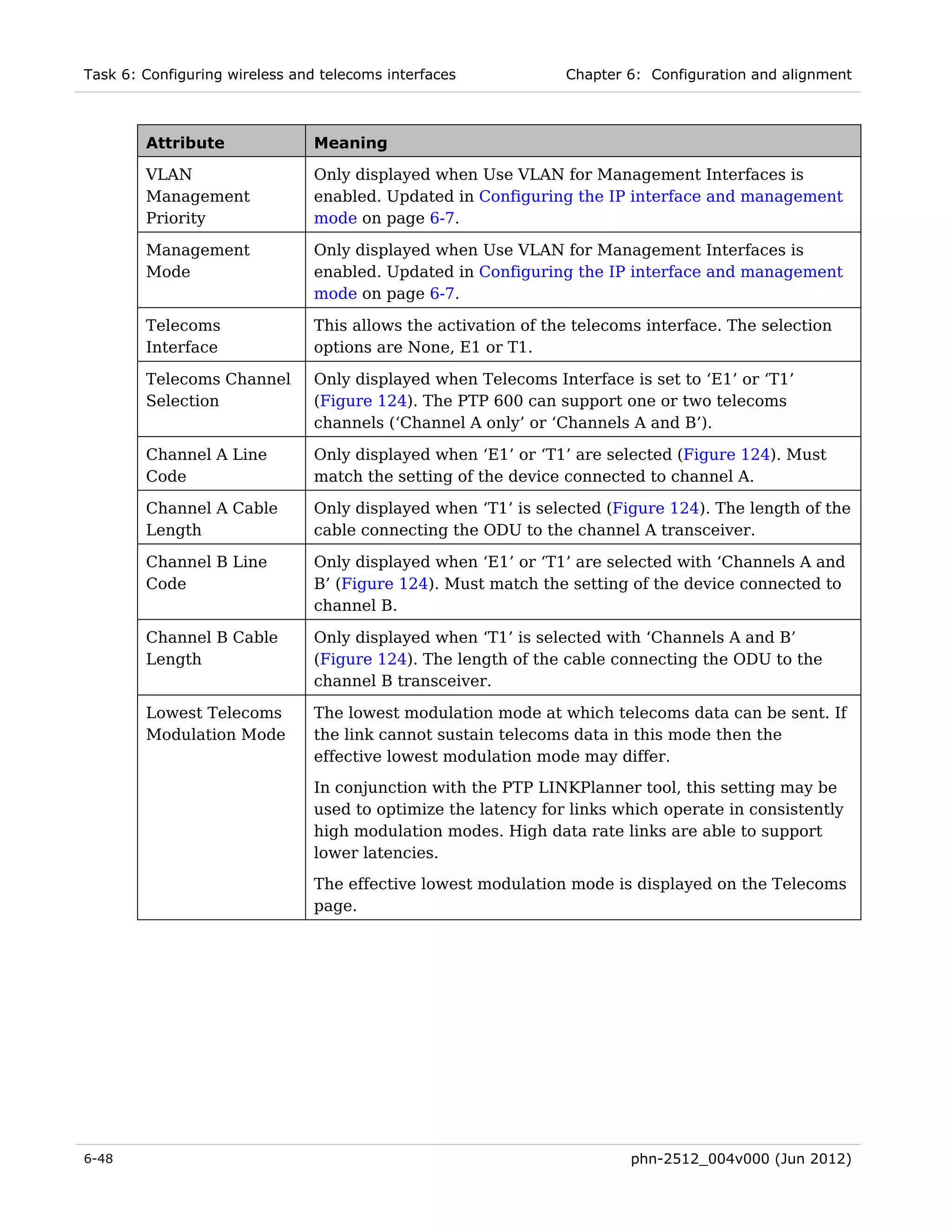
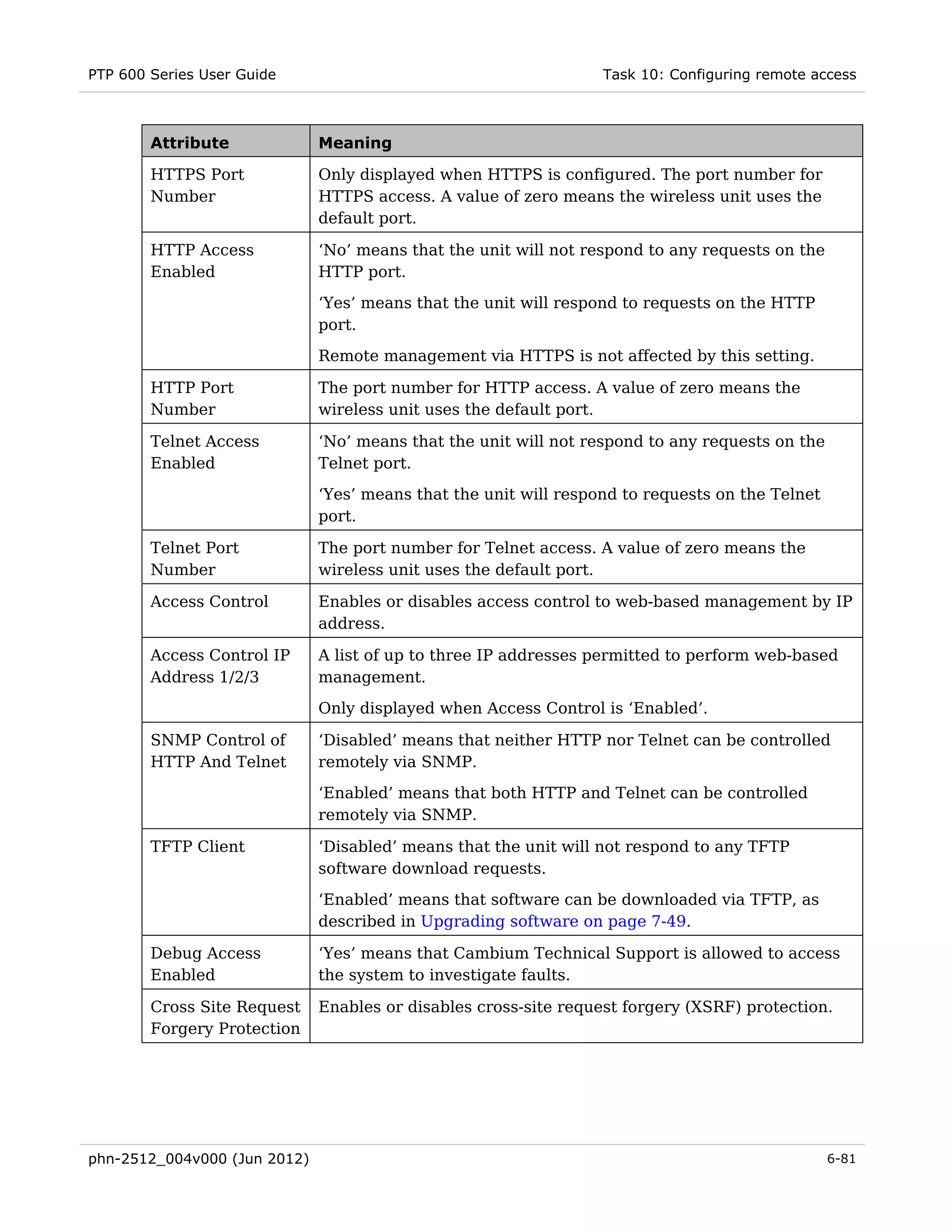
![Task 6: Configuring wireless and telecoms interfaces Chapter 6: Configuration and alignment
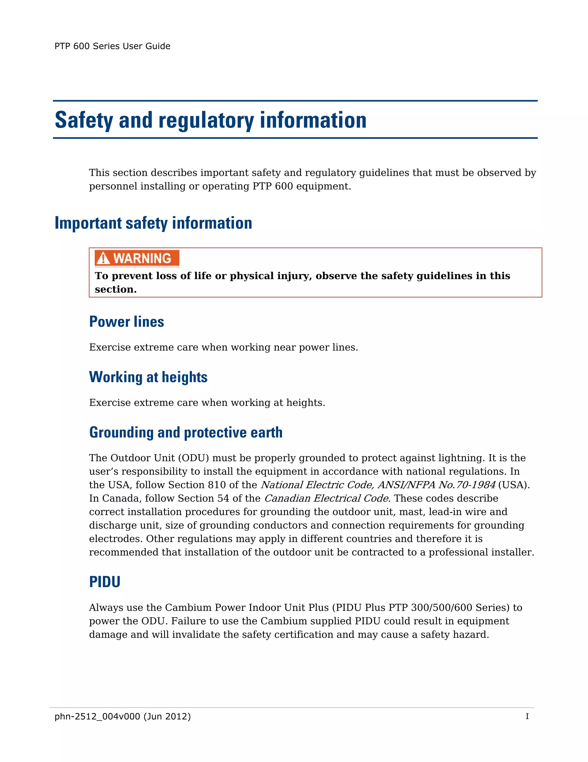
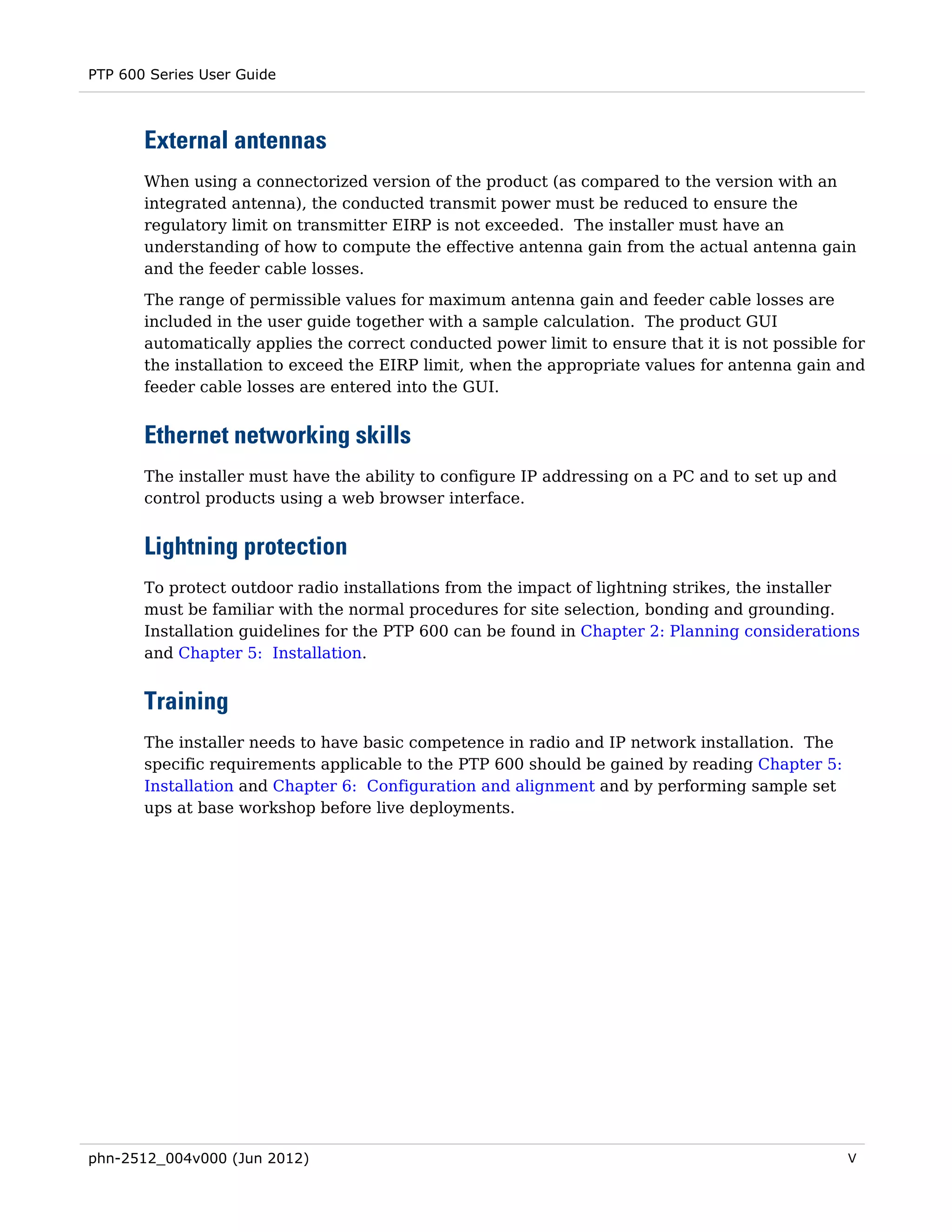
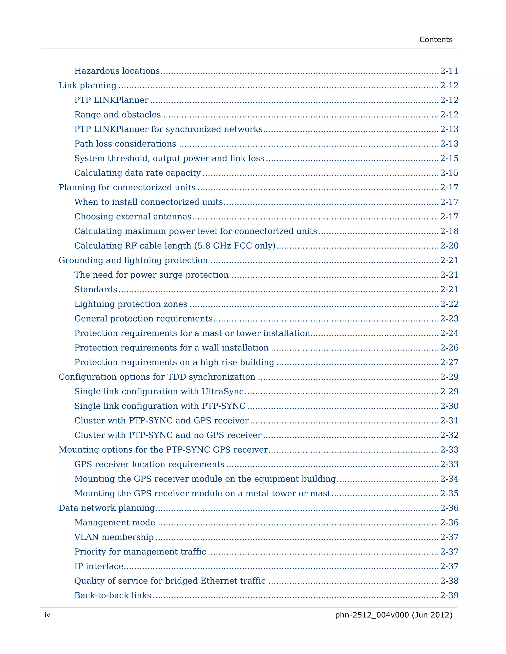
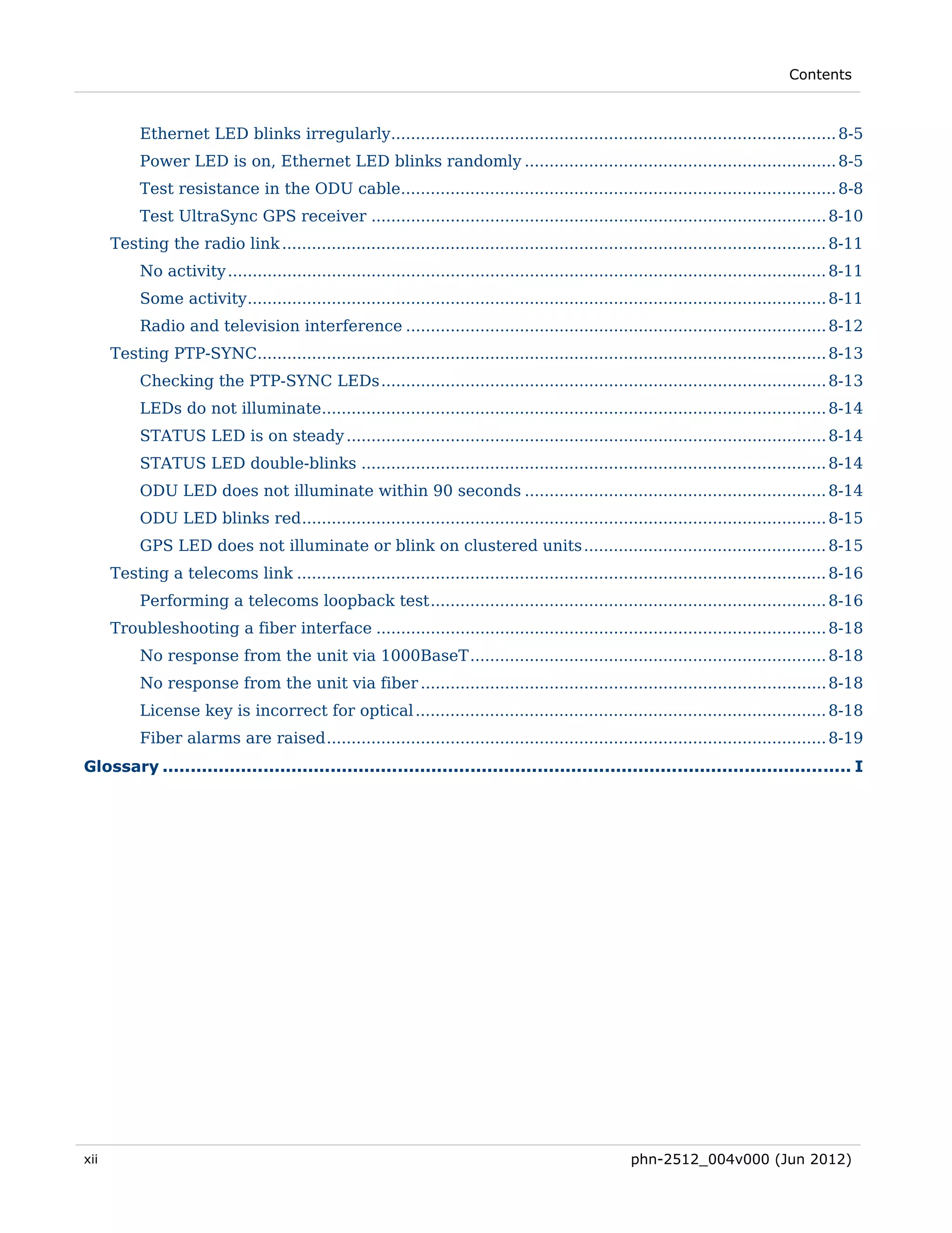
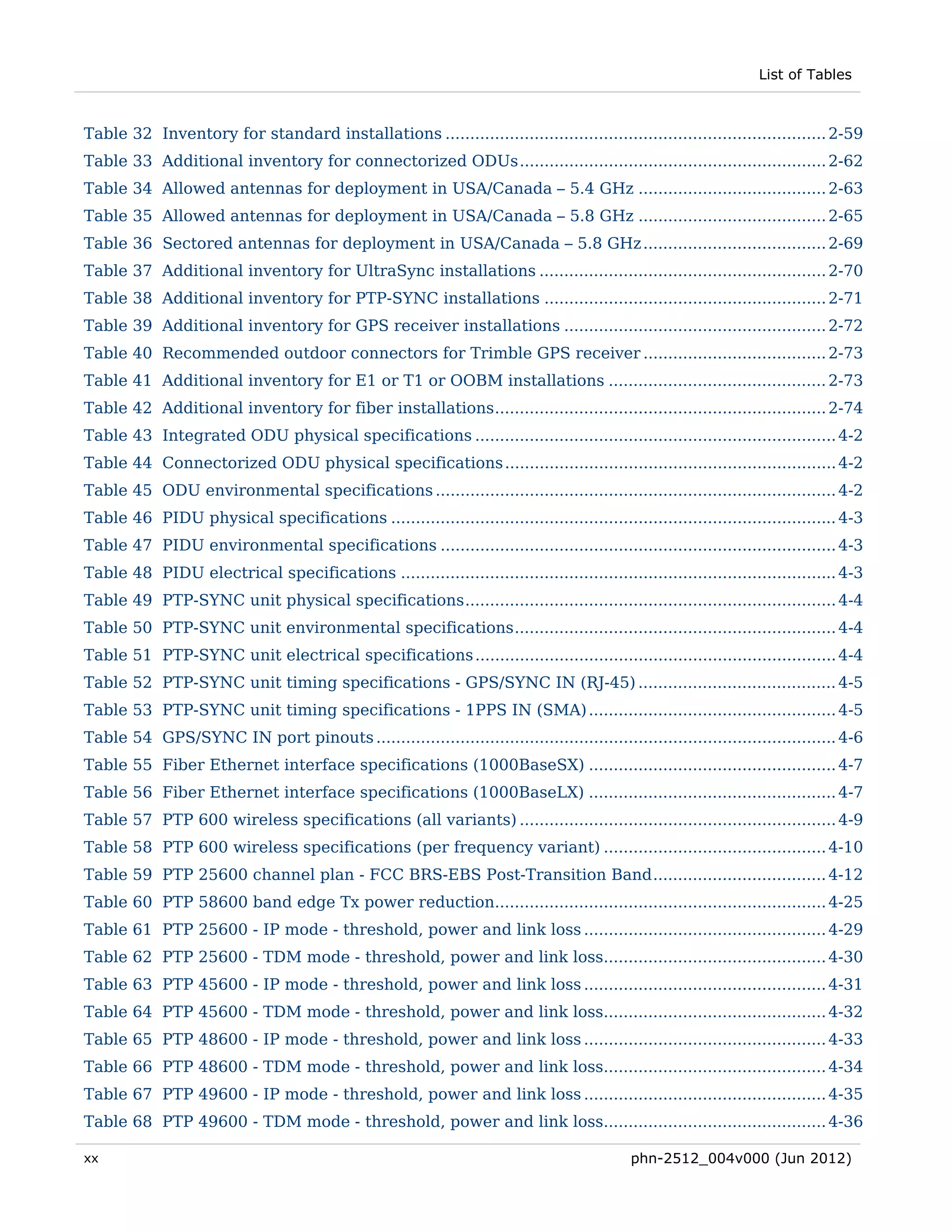
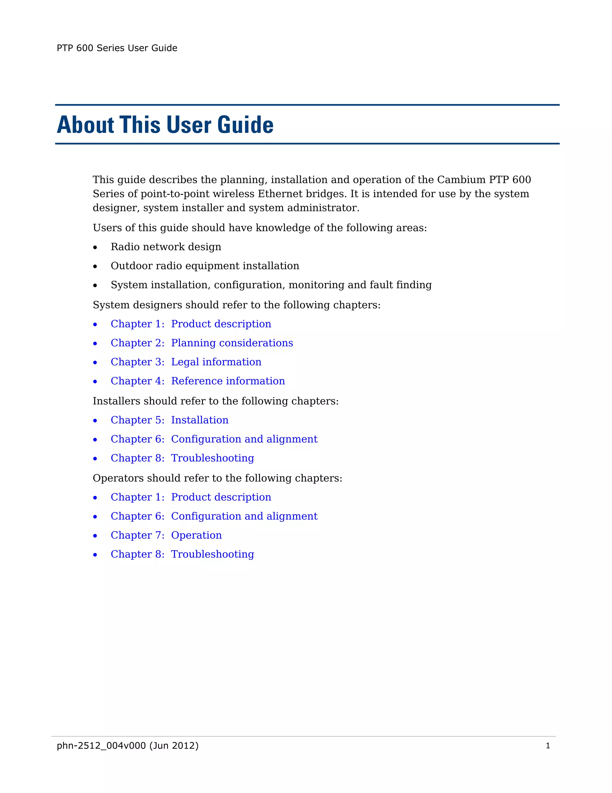
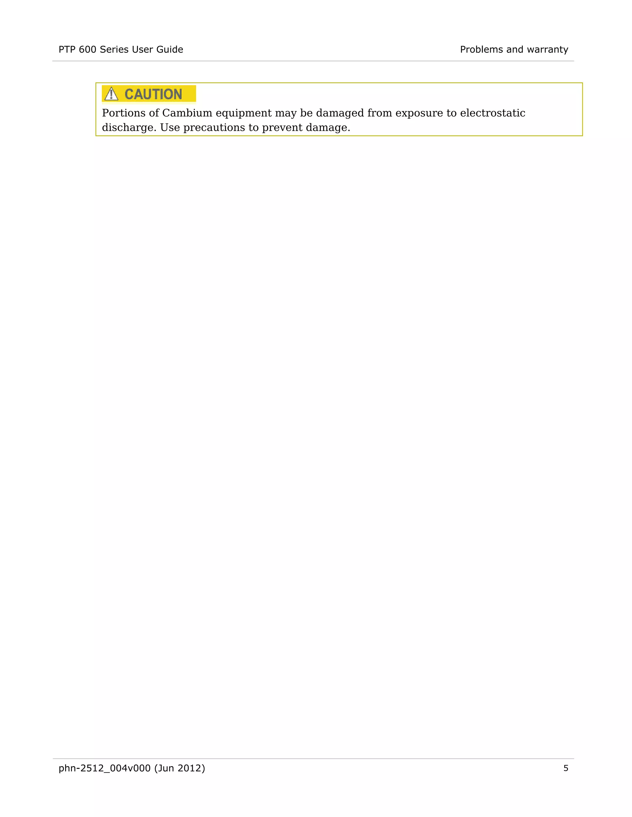
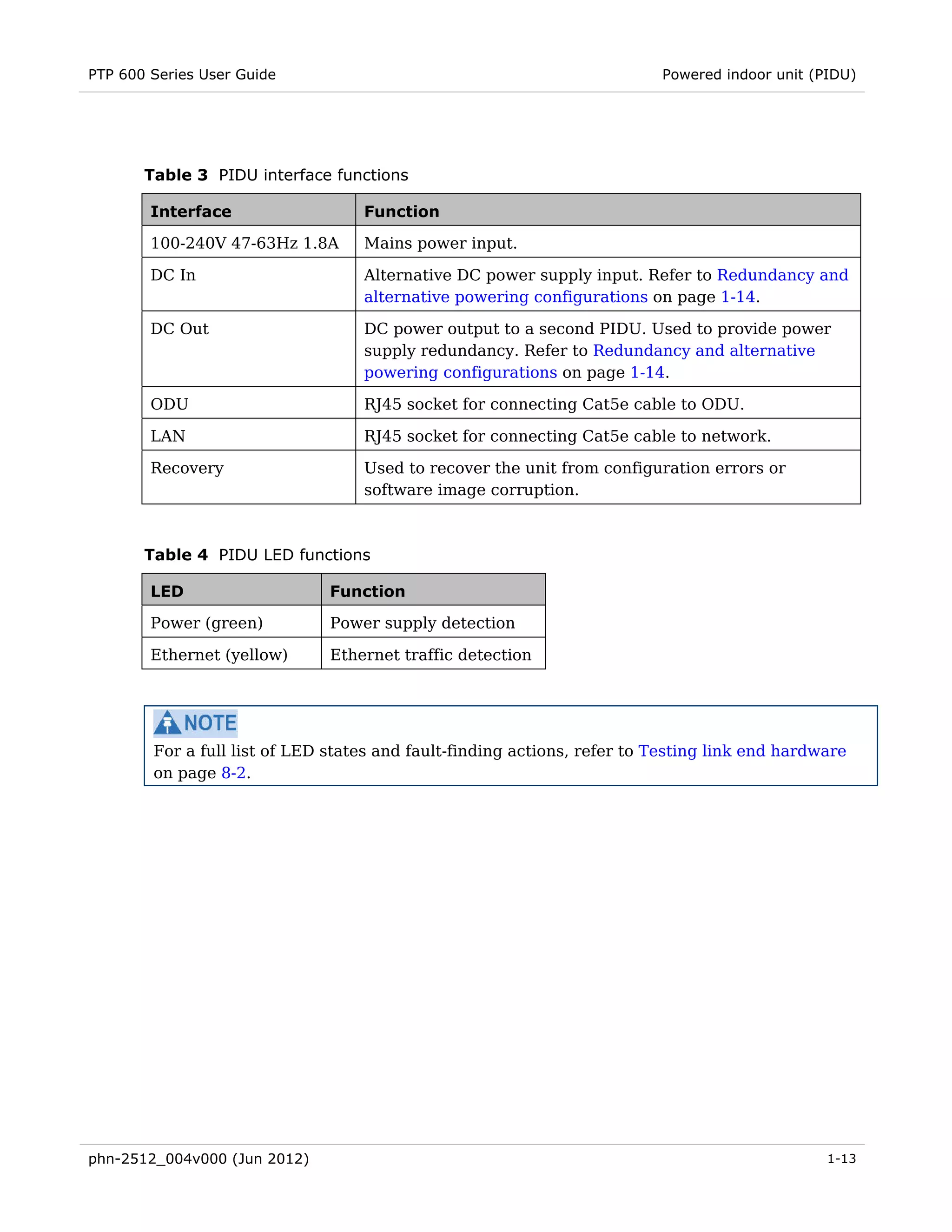
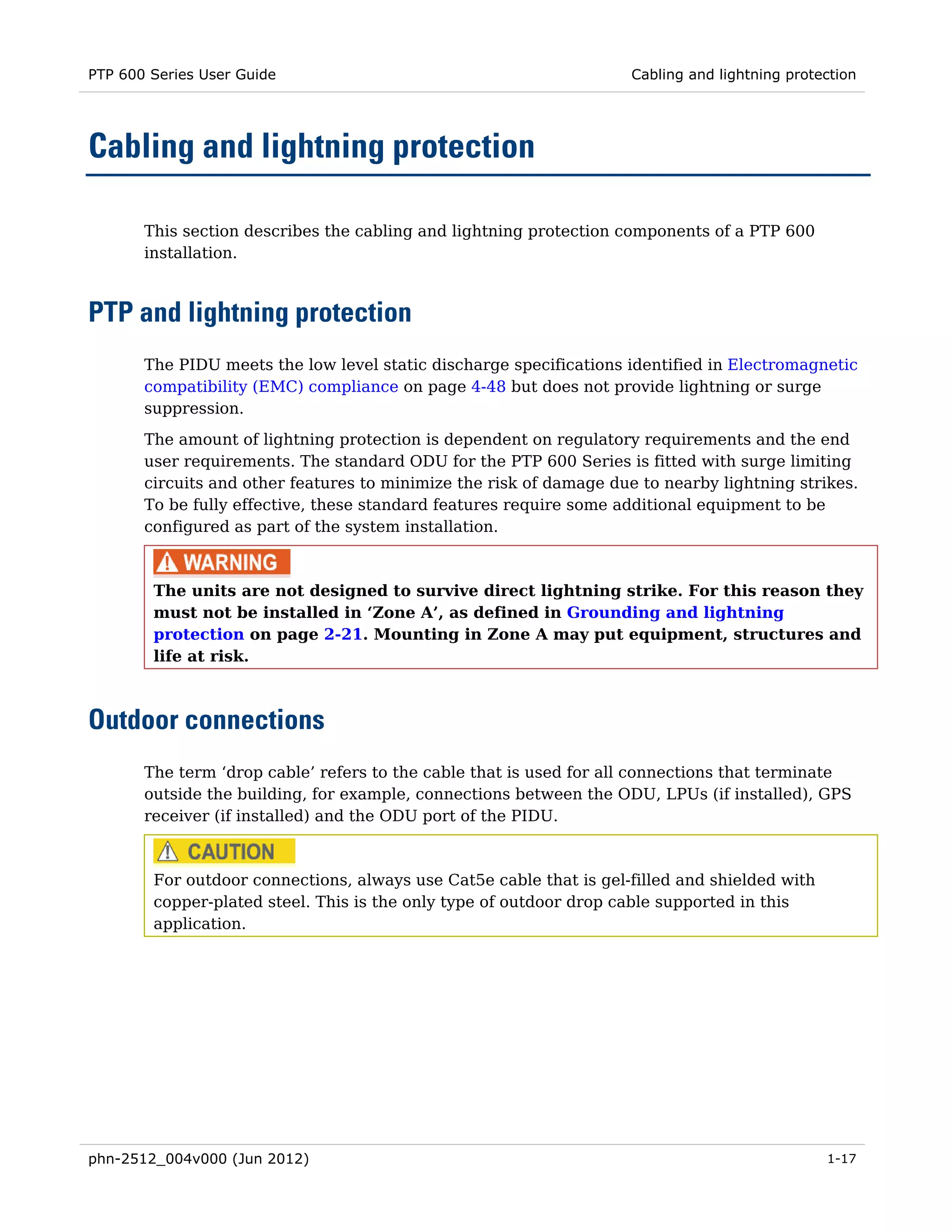
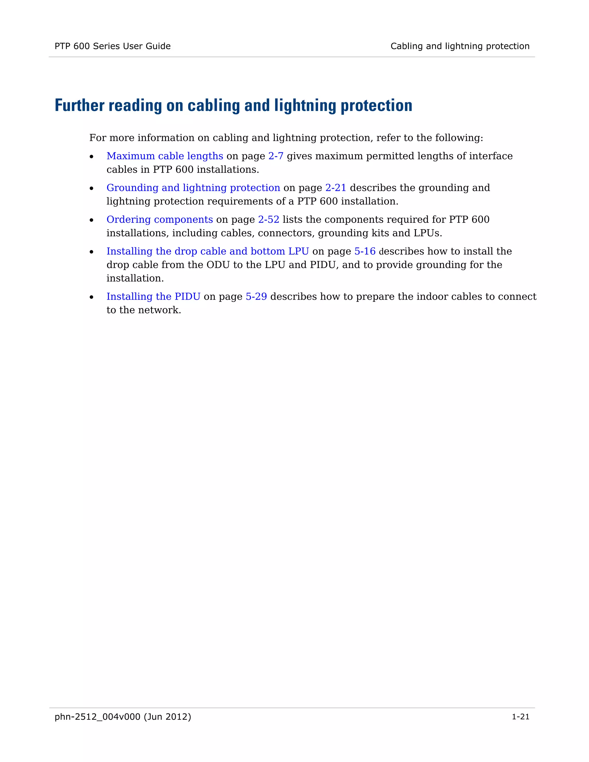
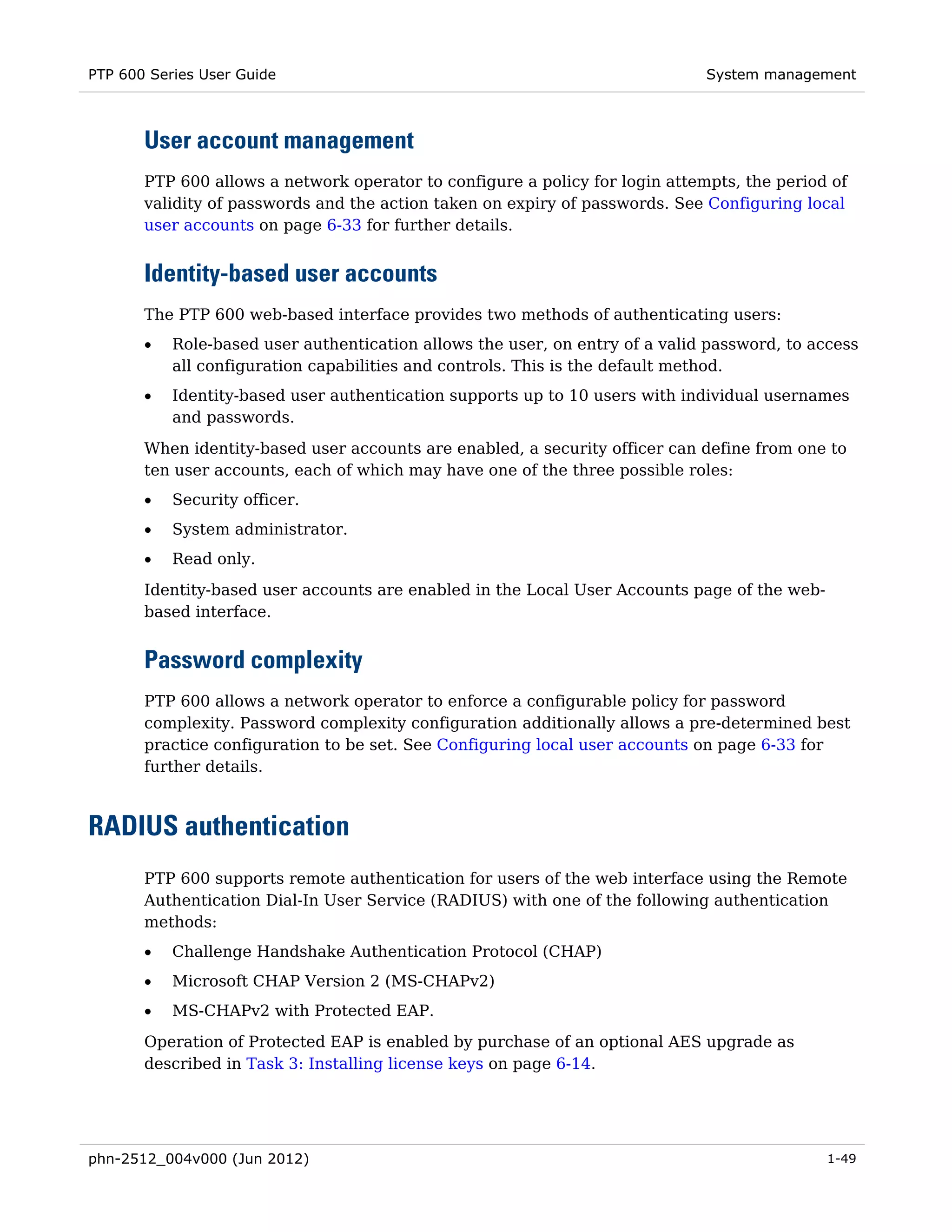
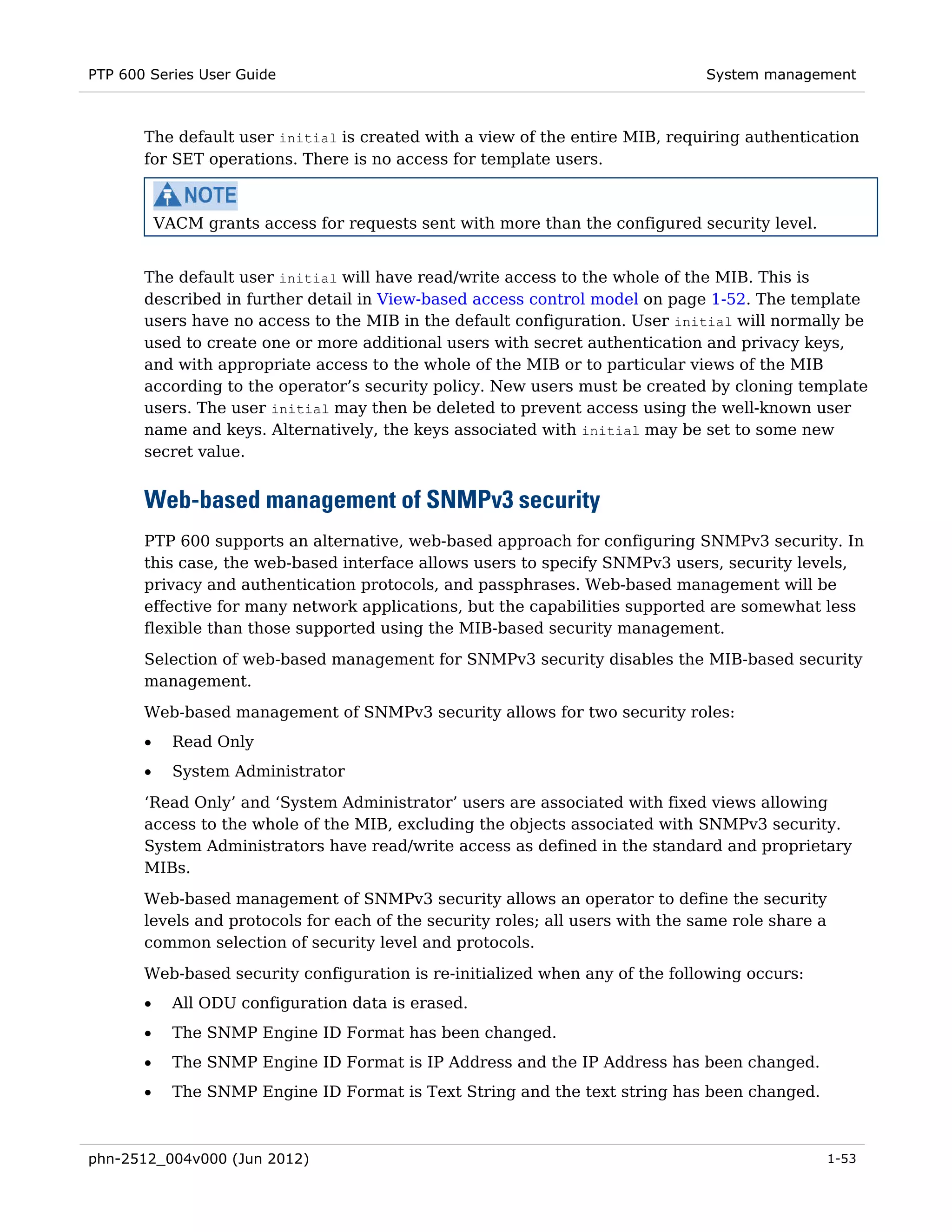
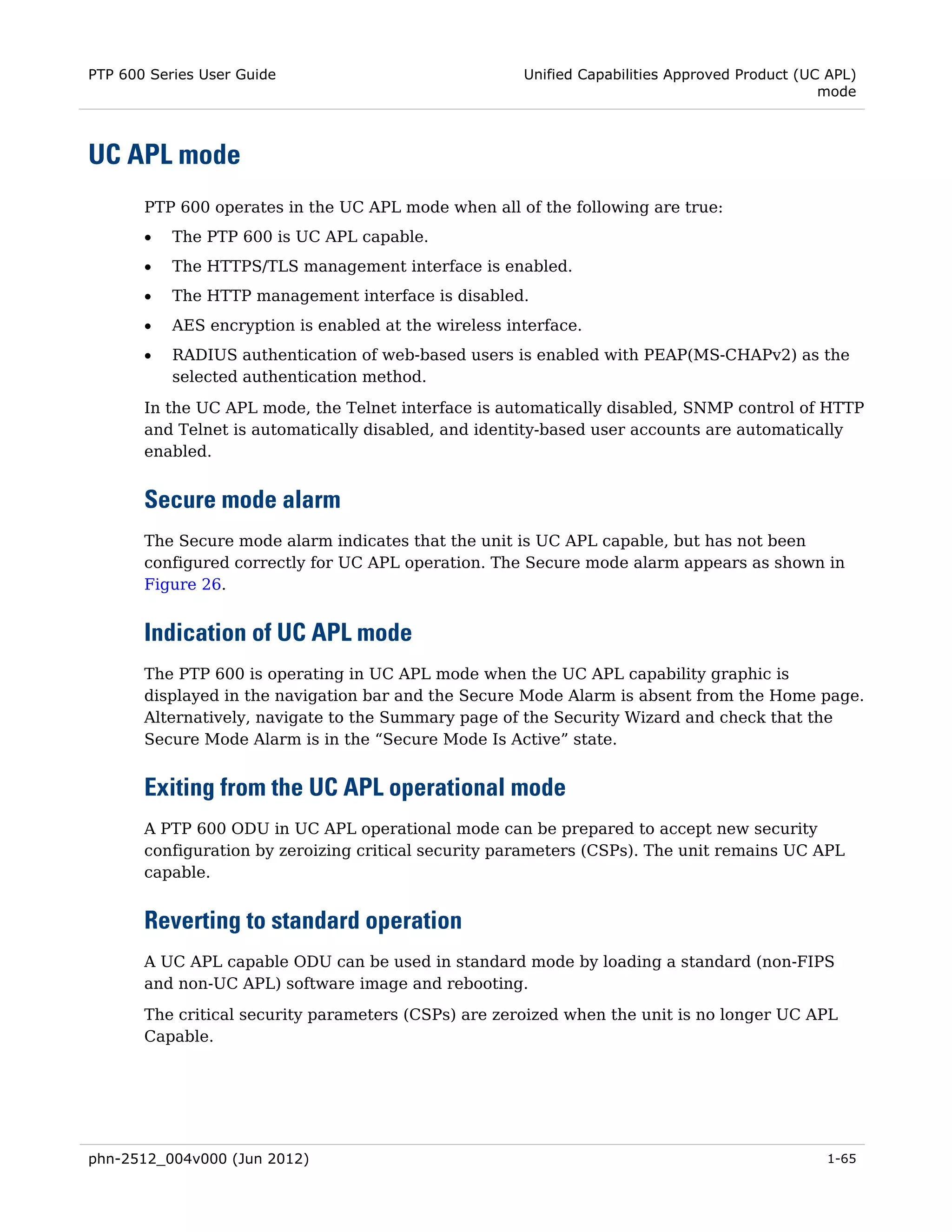
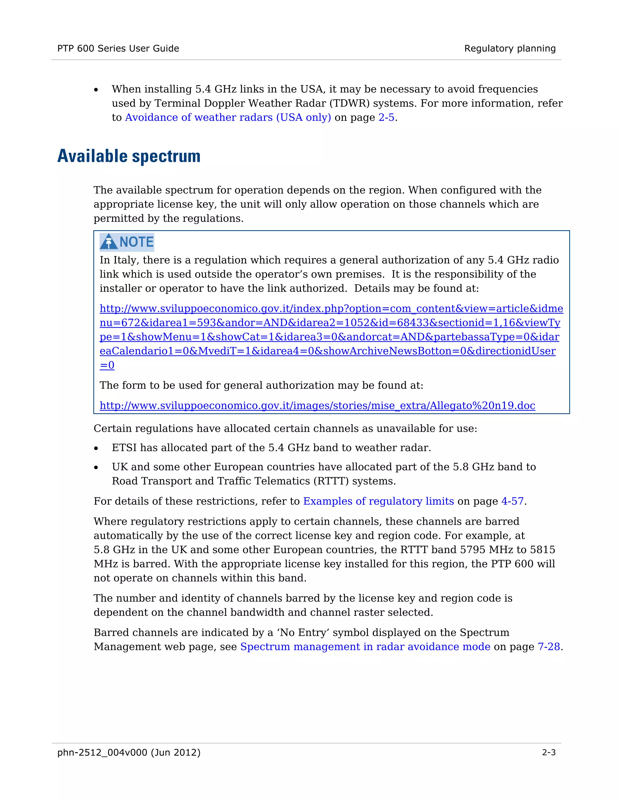
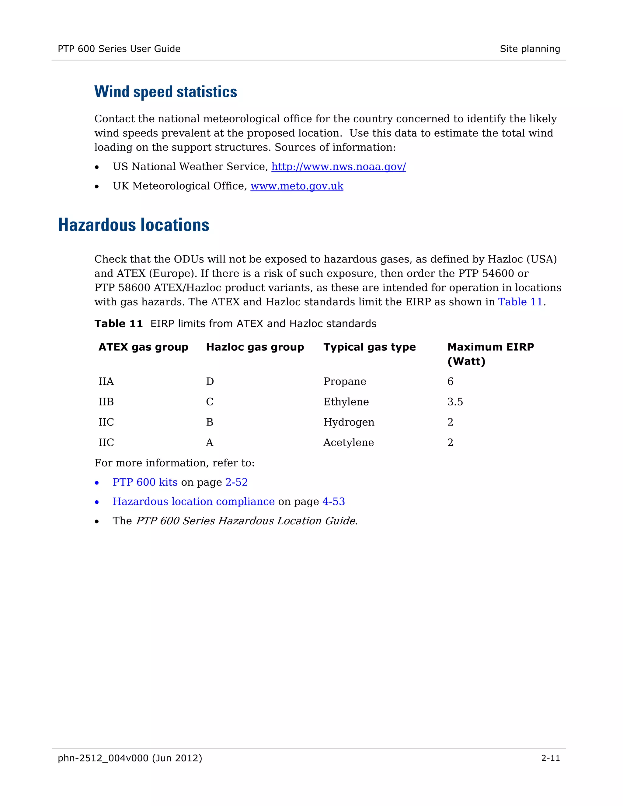
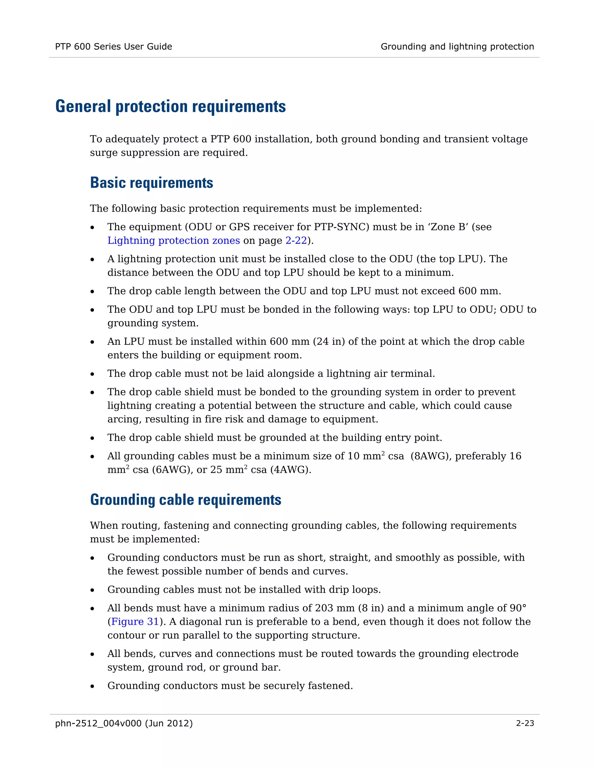
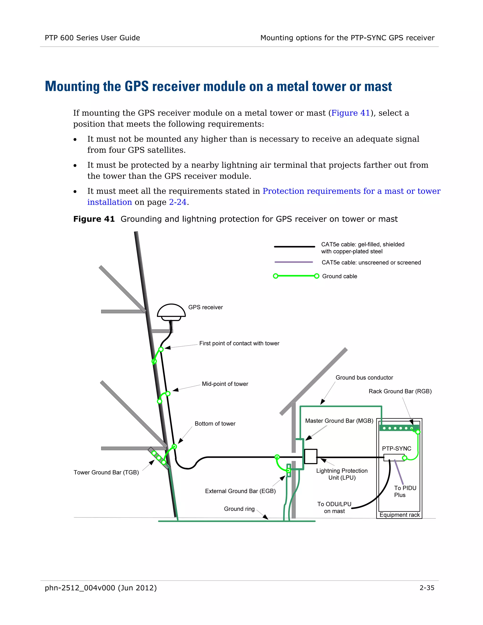
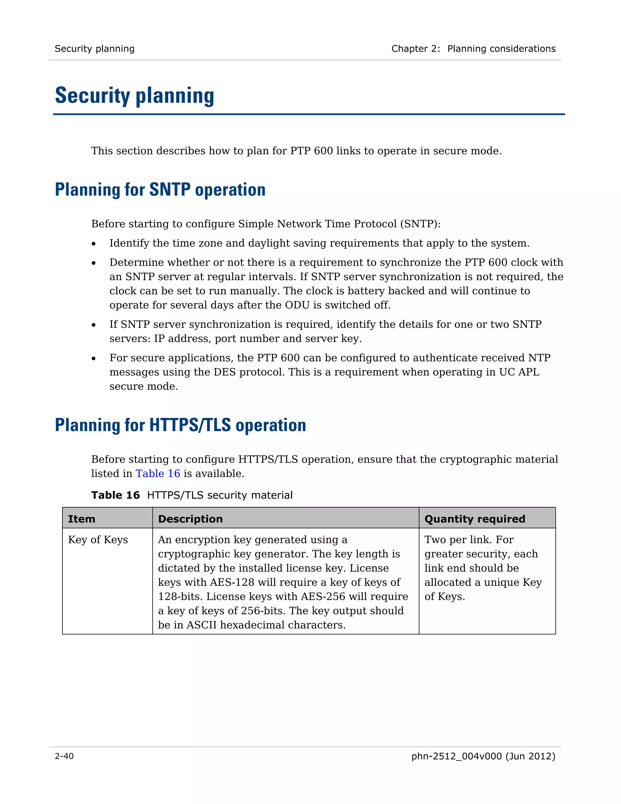
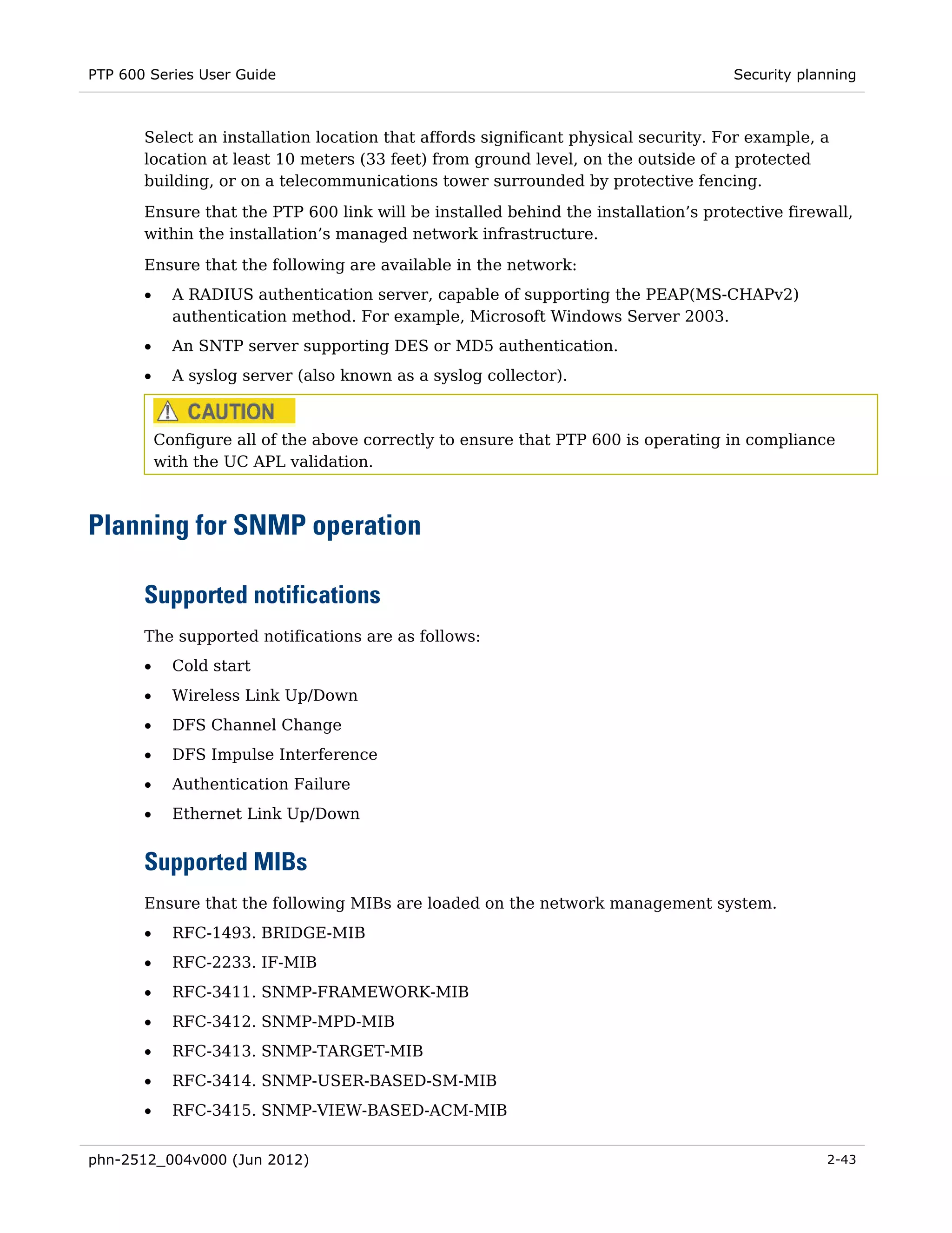
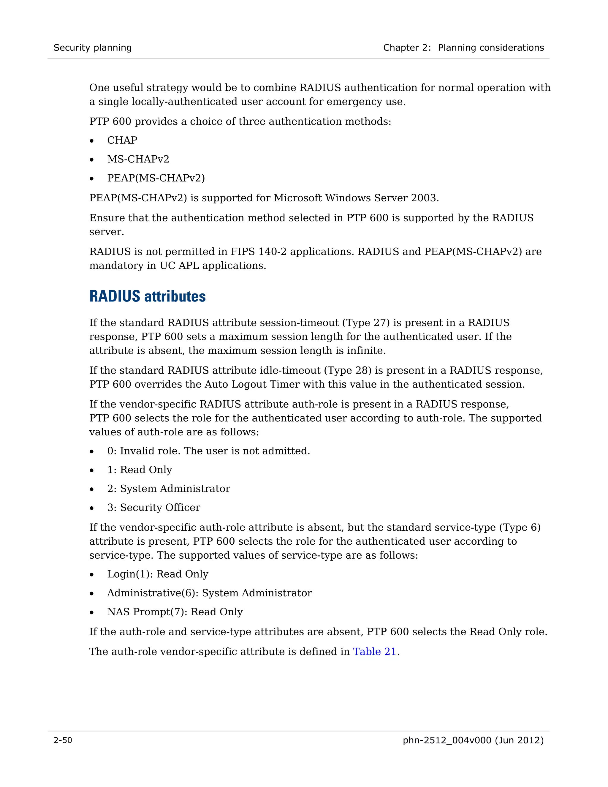
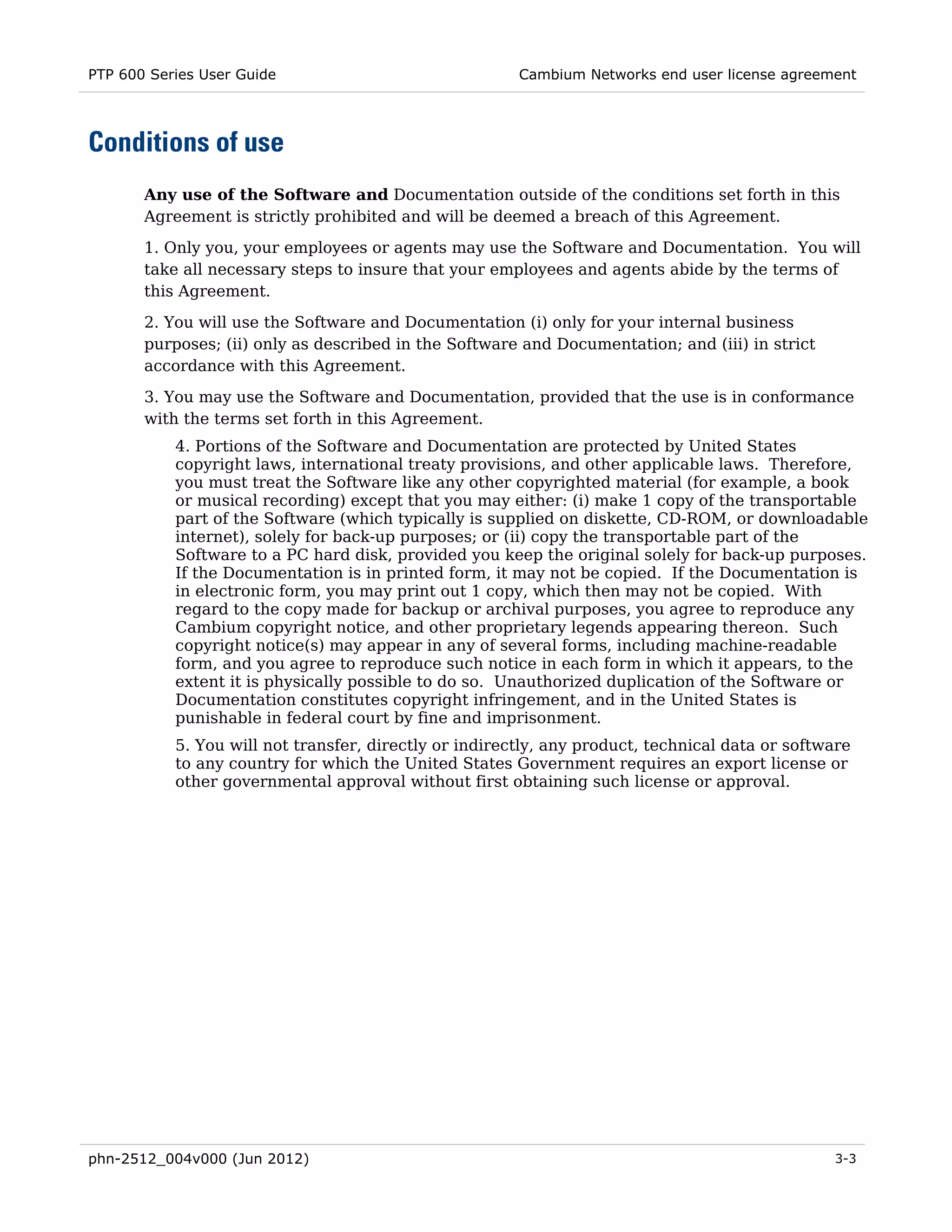
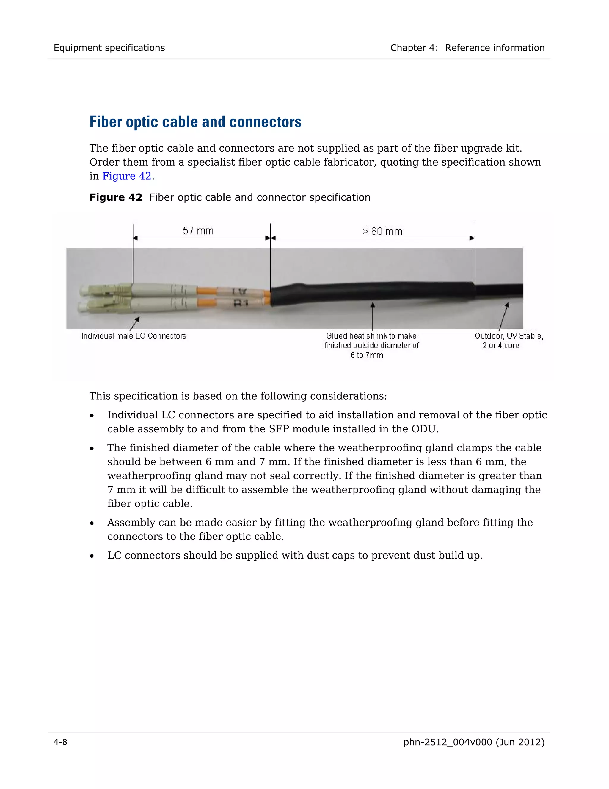
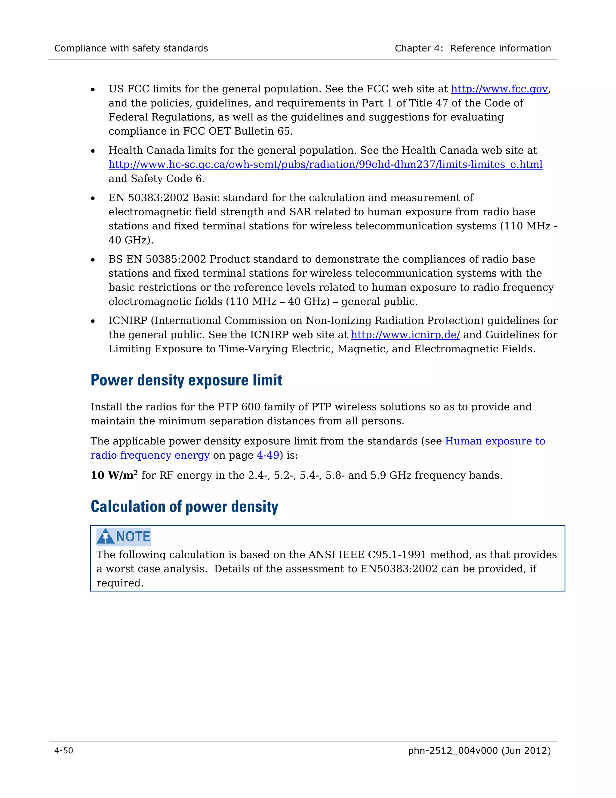
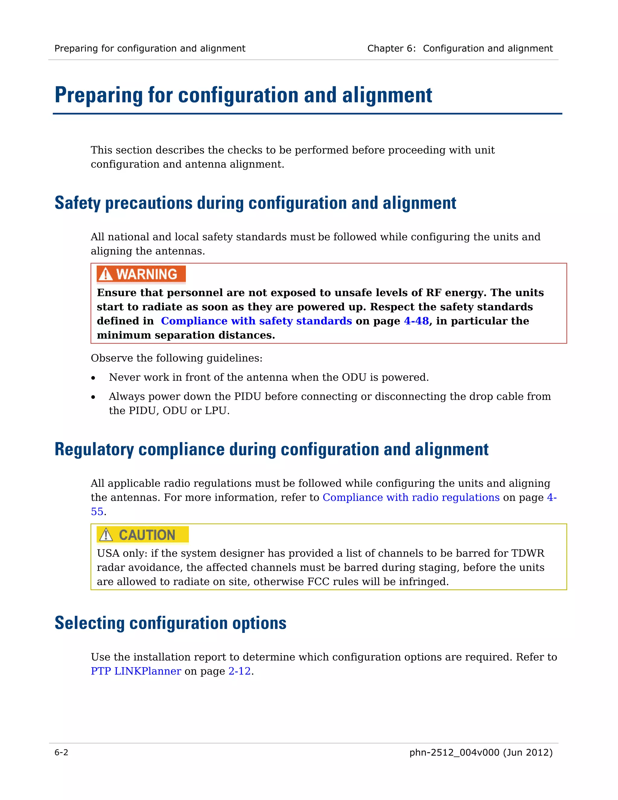
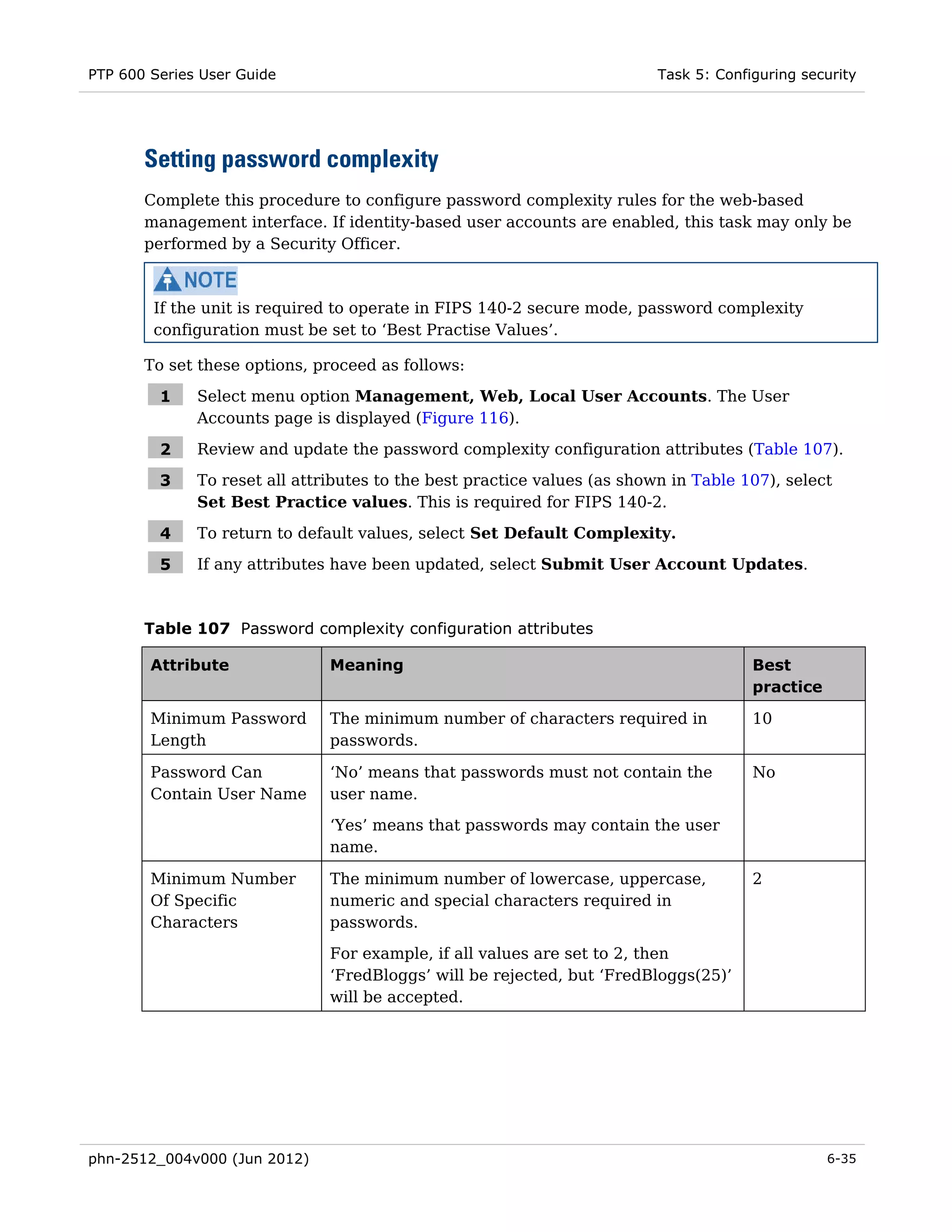
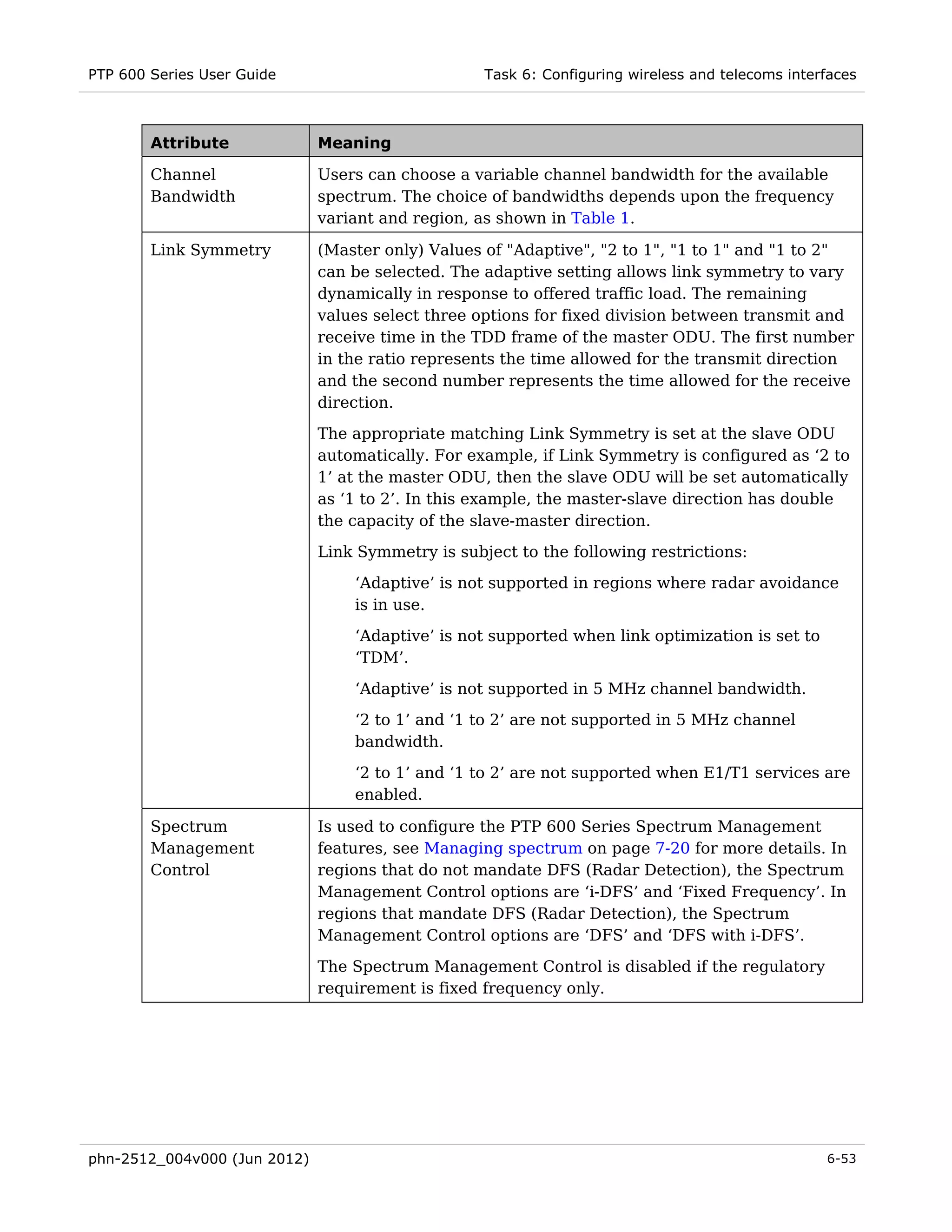
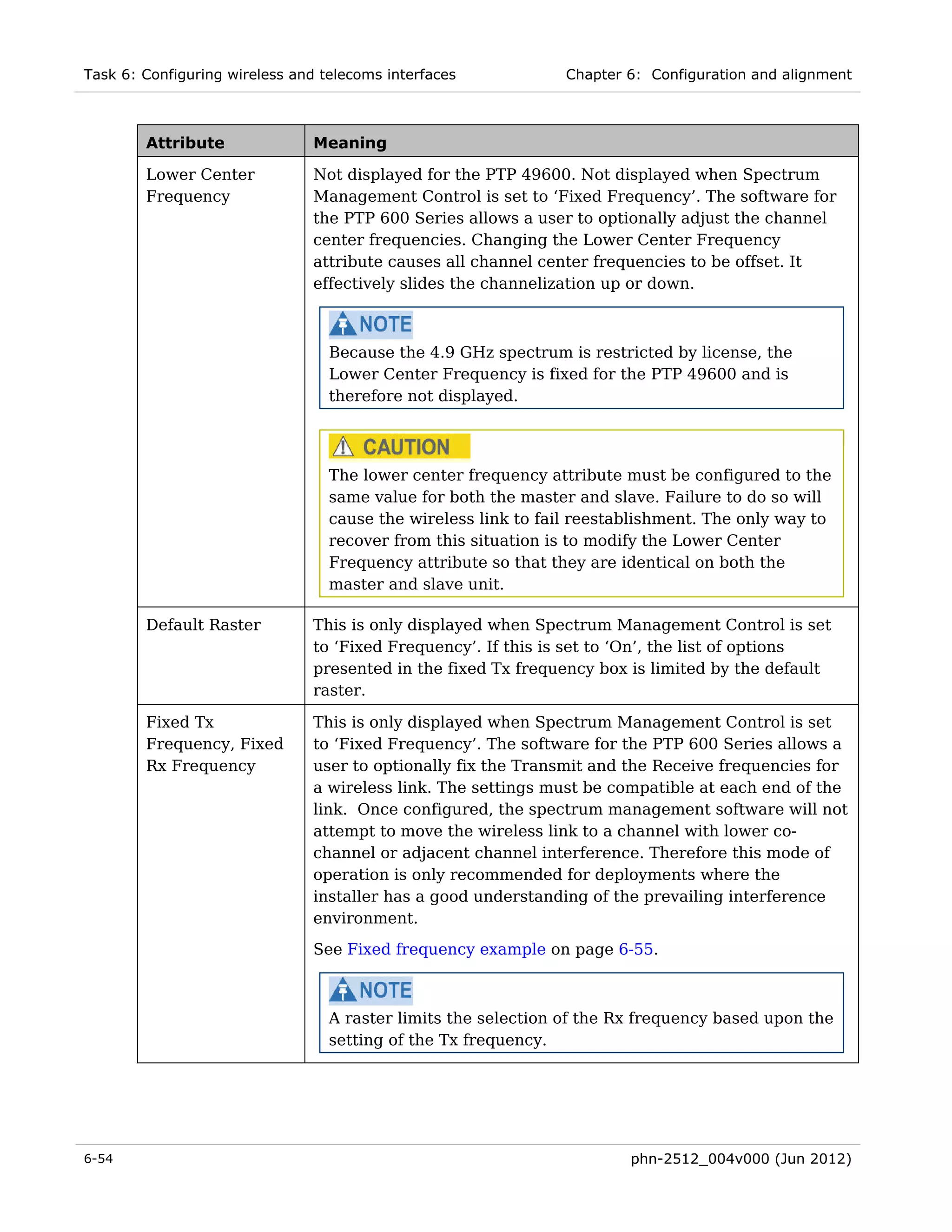
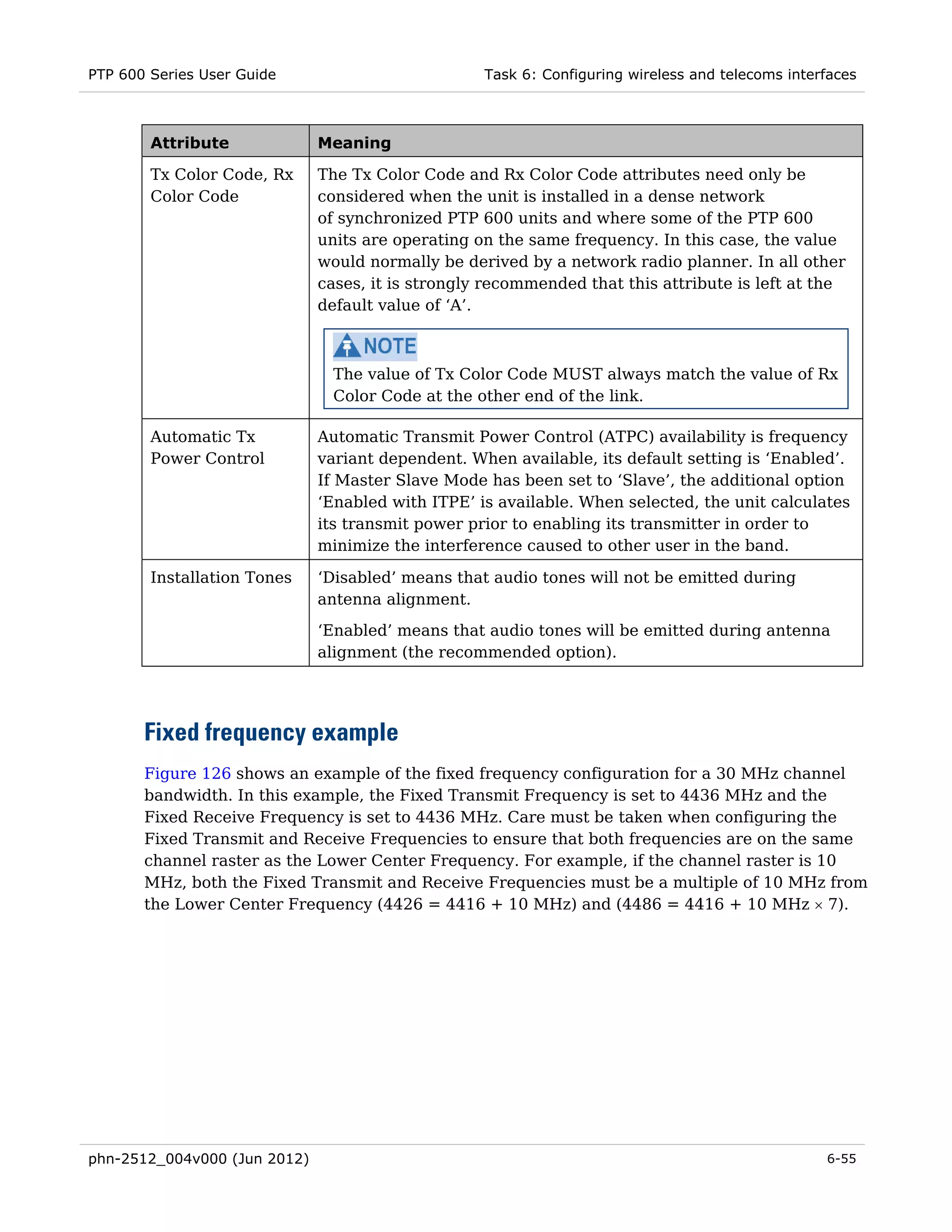
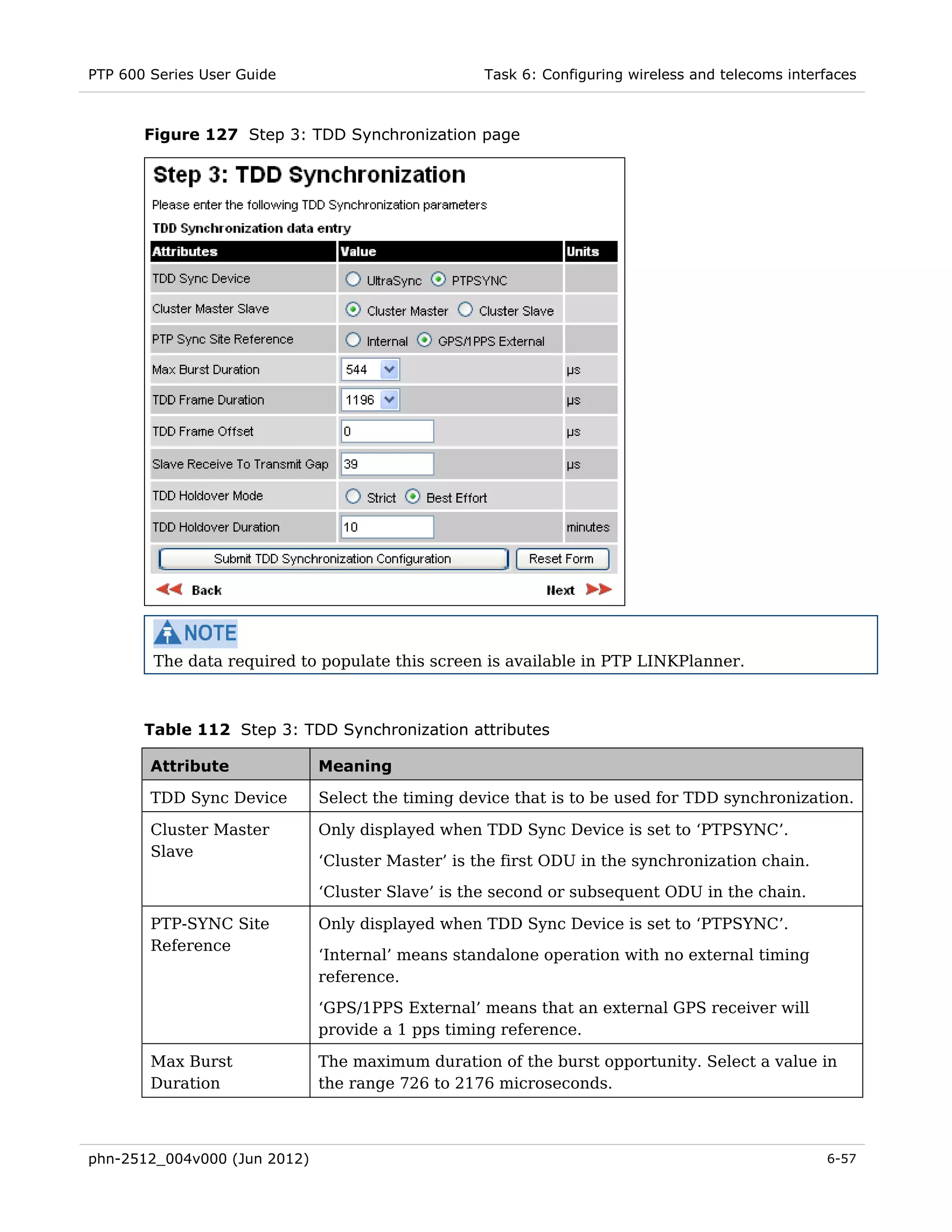
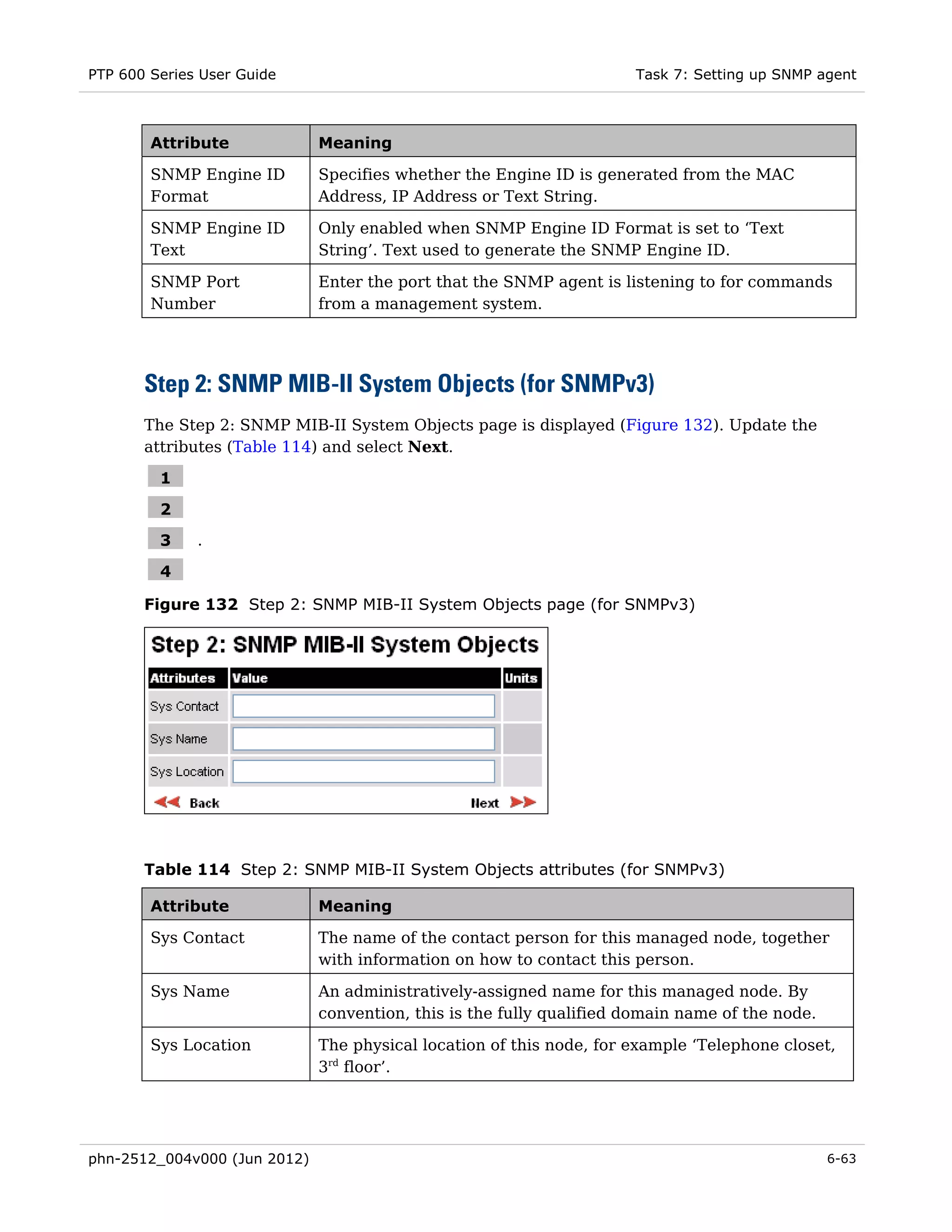
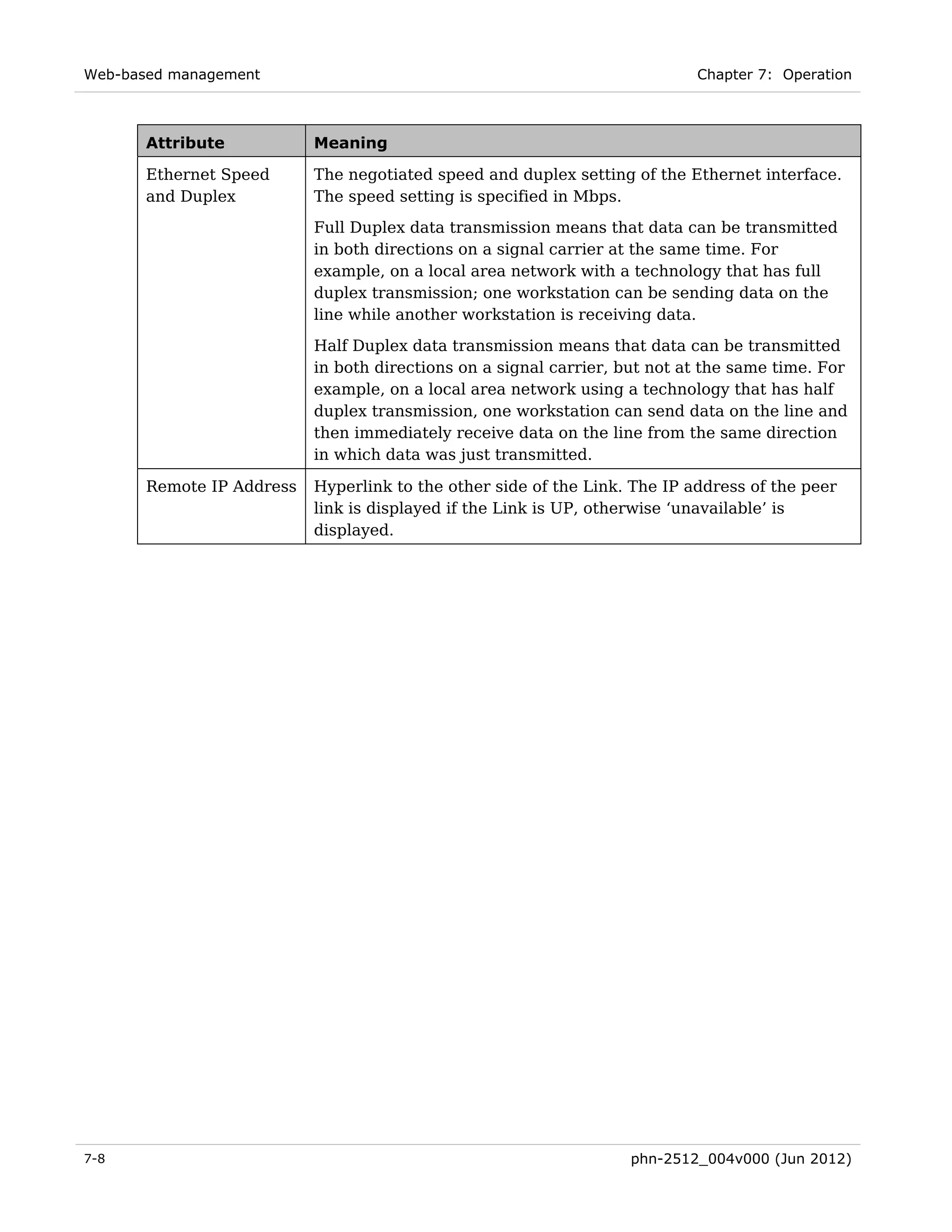
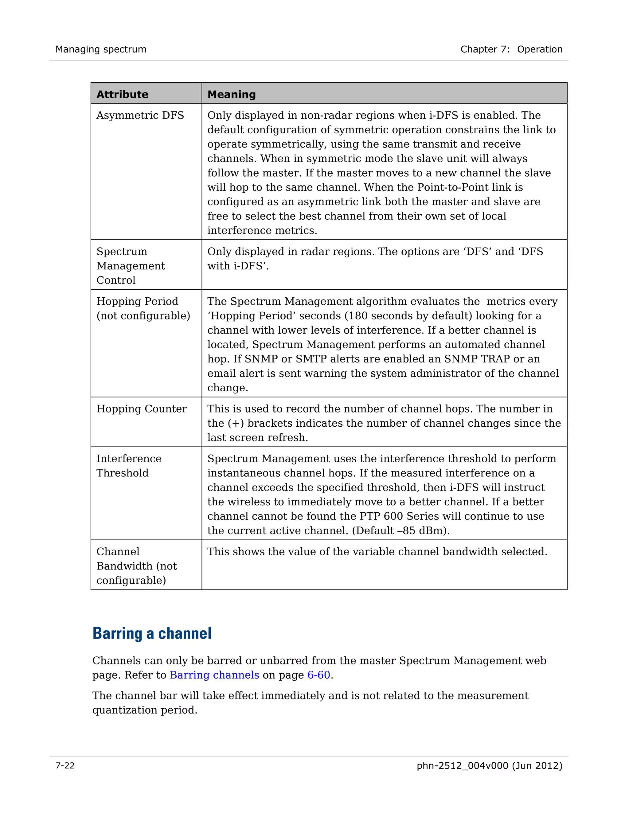
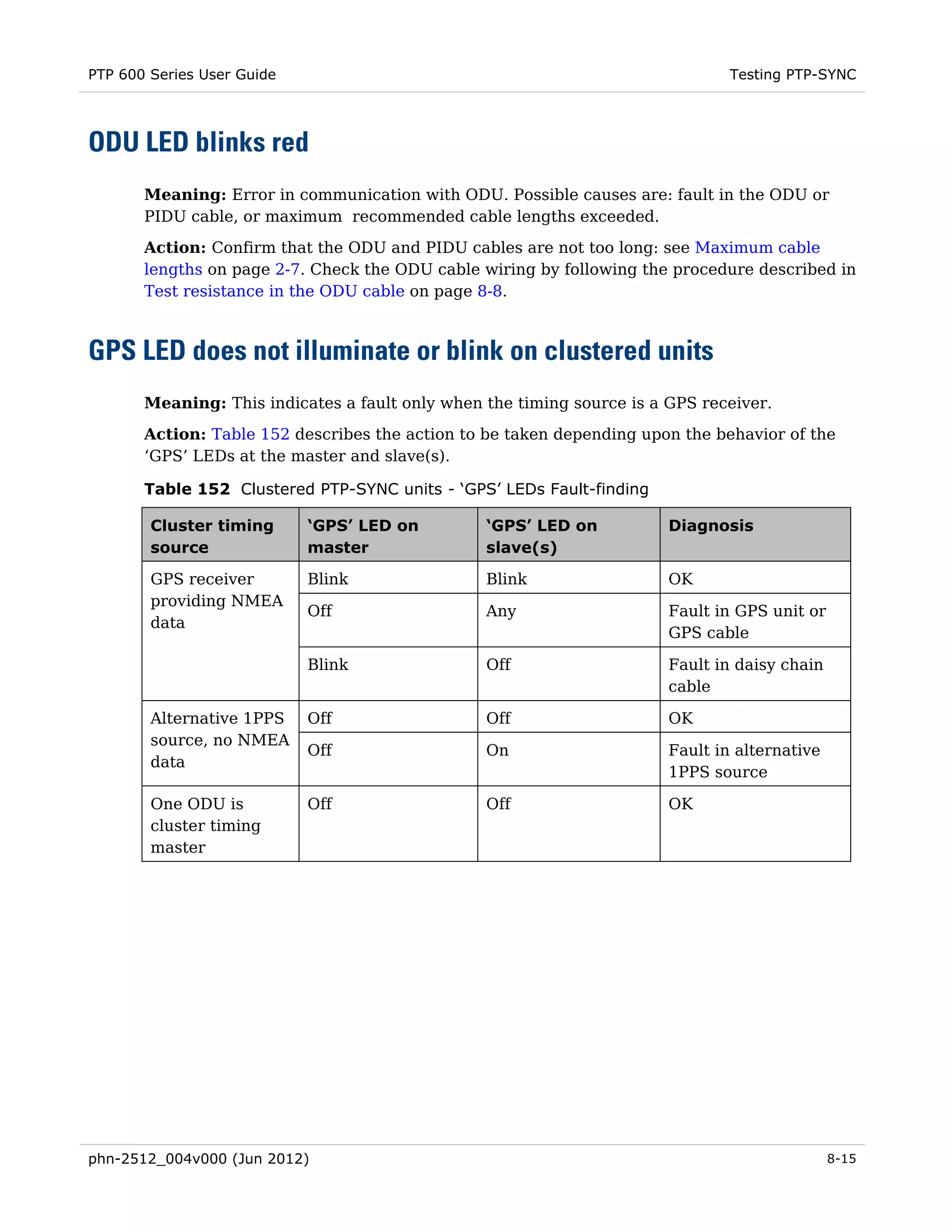
Table 111 Step 2: Wireless Configuration attributes
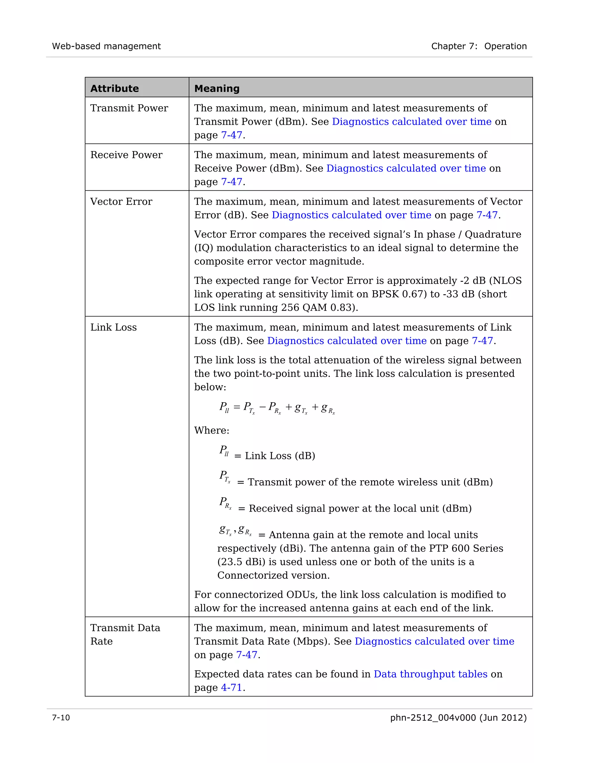
Attribute Meaning
Access Method ‘Link Access’ means that the link is established between a pre-
paired Master and Slave.
‘Link Name Access’ means that a link can only be established
between units that have identical Link Name attributes.
‘Group Access’ means that a link can only be established between
units that have identical Group ID attributes.
Link Name Only displayed when Access Method is set to ‘Link Name Access’. A
link can only be established between units that have identical Link
Names.
Link Name may consist of letters (A-Z and a-z), numbers (0-9),
spaces, and the following special characters:
(),-.,:<=>[]_{}
Group ID Only displayed when Access Method is set to ‘Group Access’. A link
can only be established between units that have identical Group
IDs.
Target MAC This is only displayed when Access Method is set to ‘Link Access’.
Address This is the MAC Address of the peer unit that will be at the other
end of the wireless link. This is used by the system to ensure the
unit establishes a wireless link to the correct peer. The MAC
Address can be found embedded within the serial number of the
unit. The last six characters of the serial number are the last three
bytes of the unit’s MAC address.
A PTP 600 Series system is shipped as a pair of units with pre-
loaded correct MAC addresses. Target MAC addresses will
only need to be entered if an existing unit has to be replaced in
the field, or the unit configuration has been erased.
Dual Payload This controls whether the link takes advantage of the channel
condition to increase the link throughput. If set to ‘Disable’, the
robustness of the link is improved. The default value is ‘Enabled’.
This control is automatically set to ‘Enabled’ if either E1 or T1 is
enabled and Lowest Telecoms Modulation Mode is set to a Dual
Payload modulation.
6-50 phn-2512_004v000 (Jun 2012)](https://image.slidesharecdn.com/ptp600userguidesystemrelease10-03-120727061124-phpapp01/75/Ptp600-user-guide-system-release-10-03-400-2048.jpg)


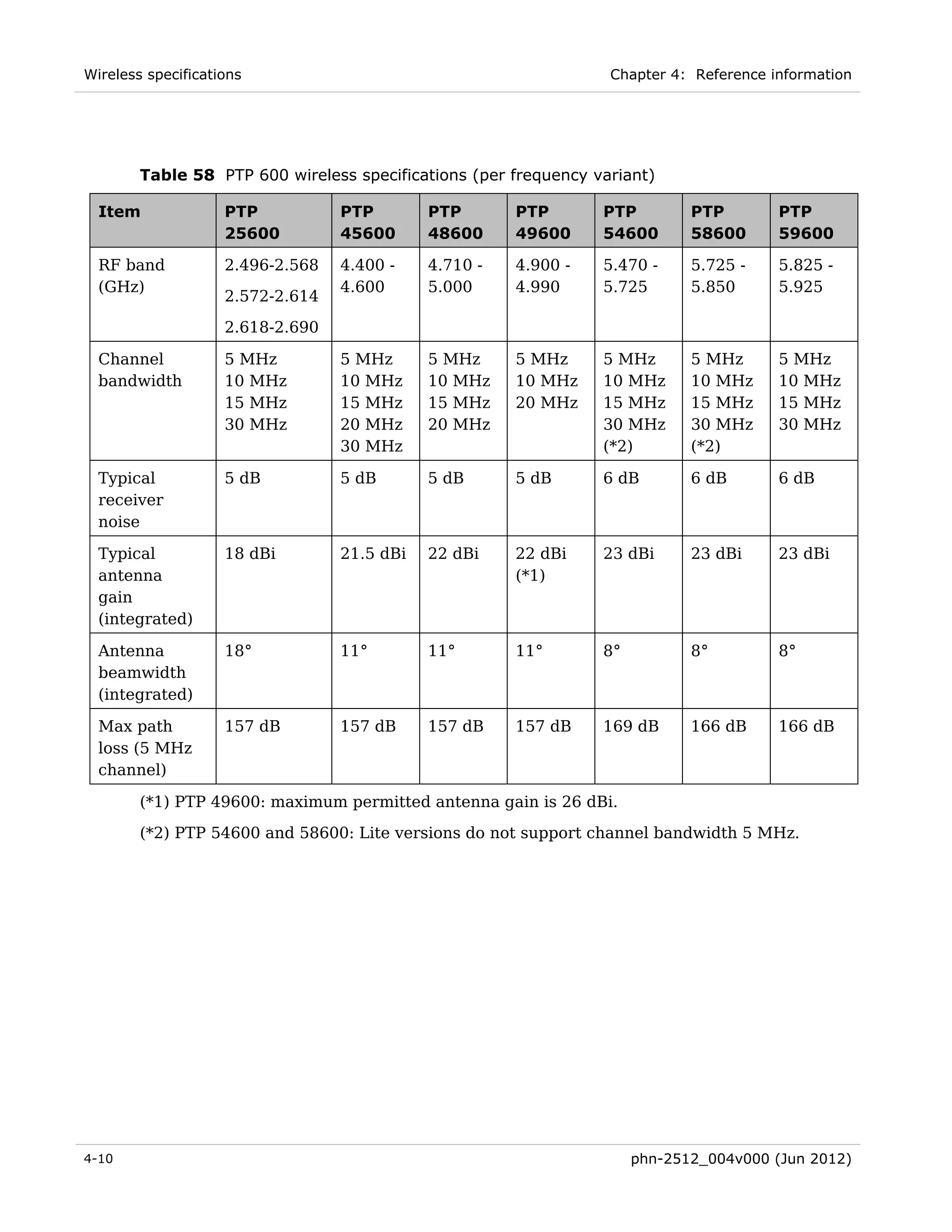
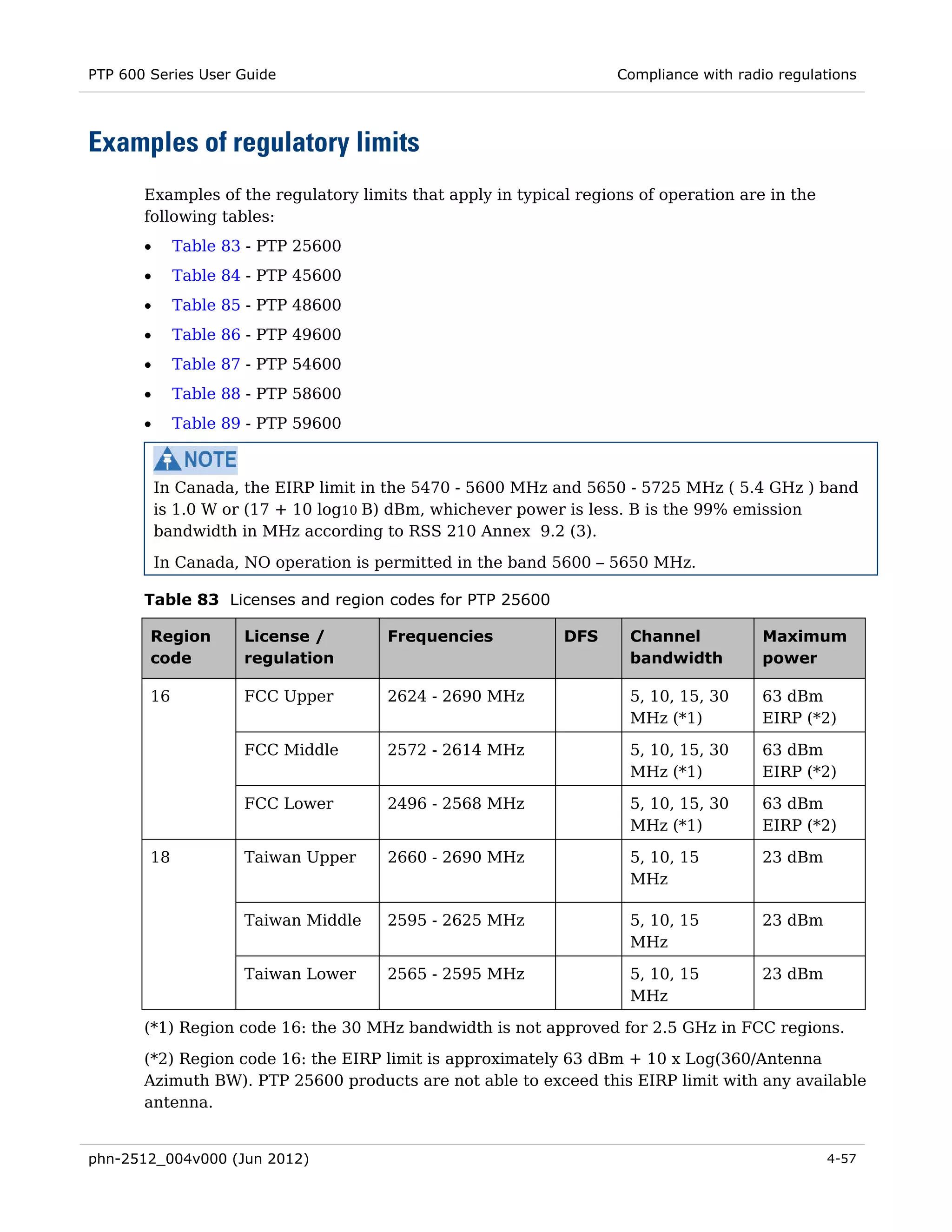
This document provides a summary of key safety and regulatory information for the Cambium PTP 600 Series product. It outlines important guidelines regarding working with power lines, at heights, and grounding and protective earth for the Outdoor Unit. It also describes regulatory requirements for unlicensed use of frequency bands and protecting radar systems from interference. The document emphasizes ensuring the correct license key and region code are set during commissioning.


