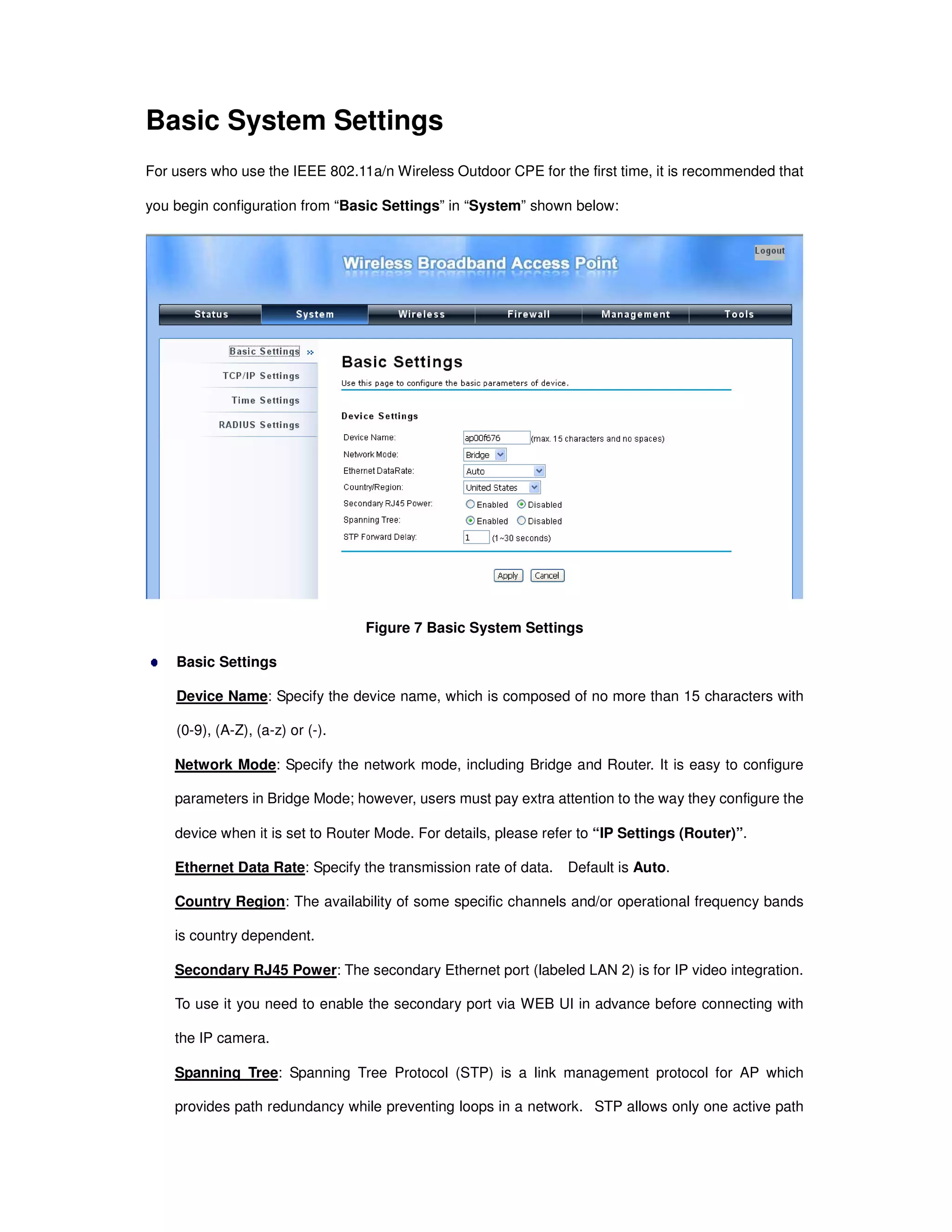
Here are the basic steps to configure the basic system settings:
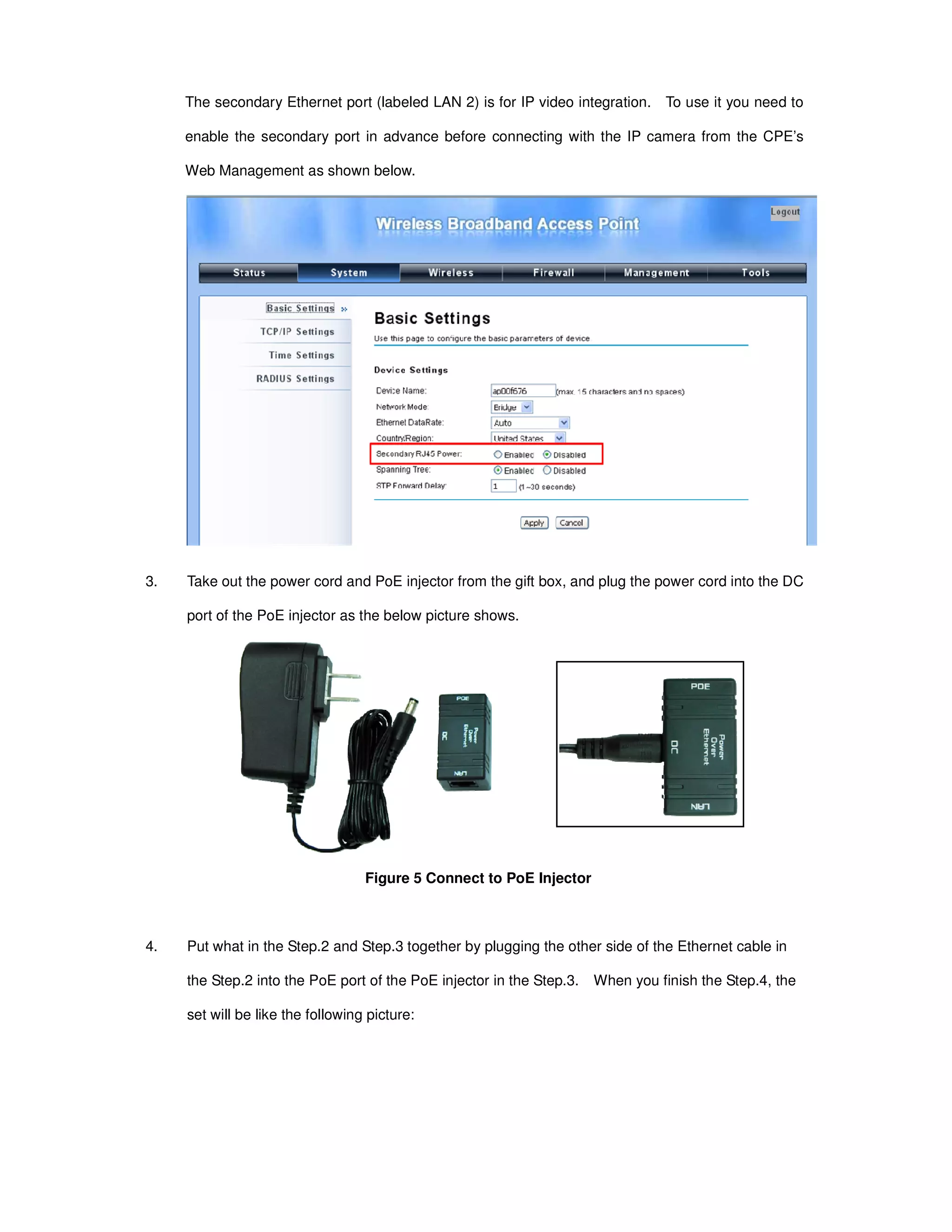
1. Specify a unique Device Name of your choice (e.g. "OutdoorAP1").
2. Select the desired Network Mode - either Bridge or Router.
3. Select the desired Ethernet Data Rate - either Auto, 10M Half, 10M Full, 100M Half, 100M Full.
4. Select your Country/Region from the dropdown list.
5. Enable or Disable the Secondary RJ45 Power as needed.
6. Click "Apply" to save the basic system settings.
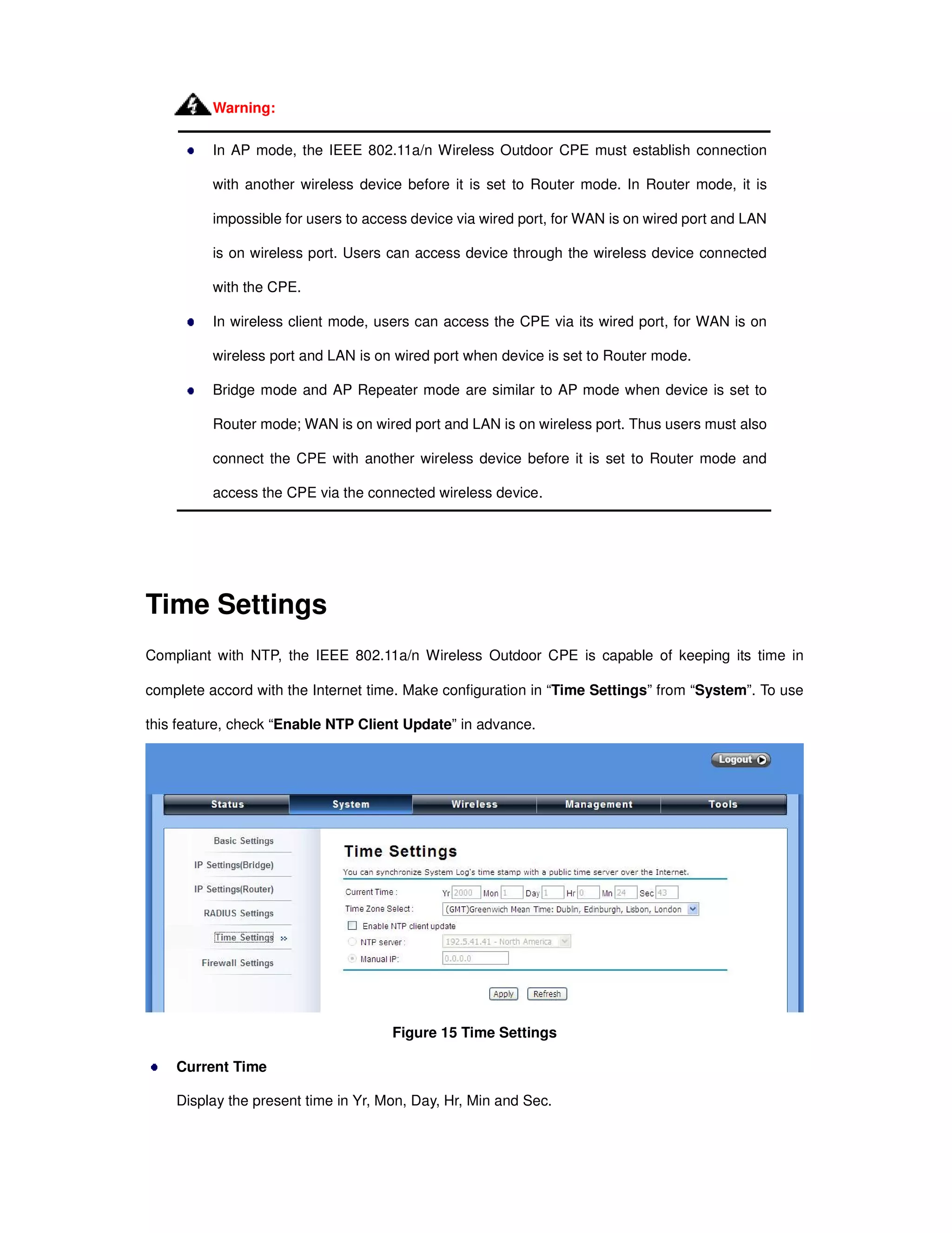
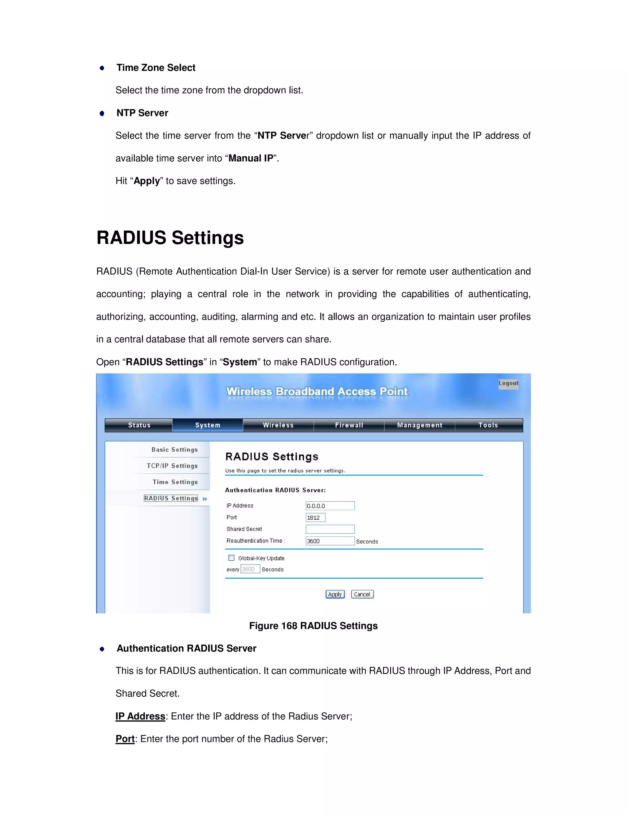
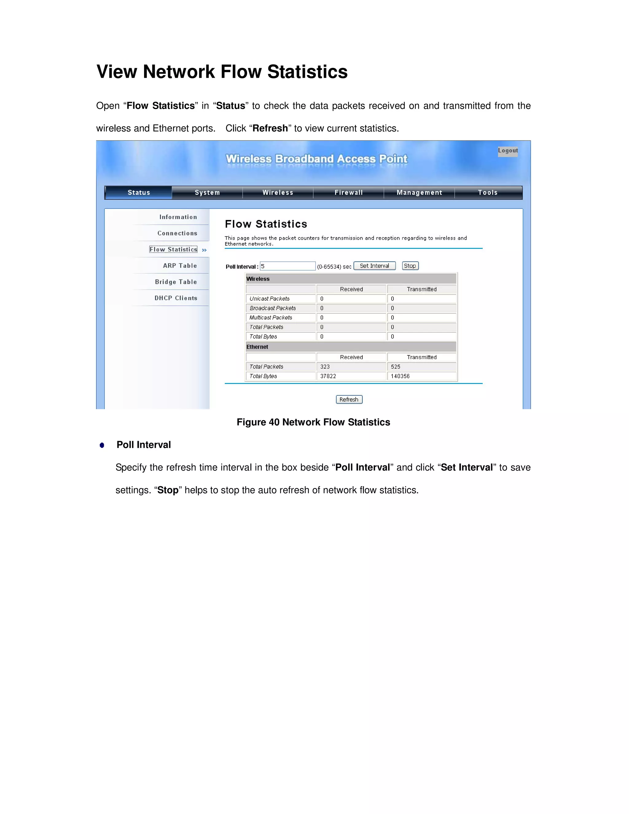
Time Settings
Time settings allow you to configure the system time of the CPE. It is recommended to synchronize the


![Appendix A. ASCII
WEP can be configured with a 64-bit, 128-bit or 152-bit Shared Key (hexadecimal number or ACSII).
As defined, hexadecimal number is represented by 0-9, A-F or a-f; ACSII is represented by 0-9, A-F,
a-f or punctuation. Each one consists of two-digit hexadecimal.
Table 2 ACSII
ASCII
Character
Hex
Equivalent
ASCII
Character
Hex
Equivalent
ASCII
Character
Hex
Equivalent
ASCII
Character
Hex
Equivalent
! 21 9 39 Q 51 i 69
" 22 : 3A R 52 j 6A
# 23 ; 3B S 53 k 6B
$ 24 < 3C T 54 l 6C
% 25 = 3D U 55 m 6D
& 26 > 3E V 56 n 6E
‘ 27 ? 3F W 57 o 6F
( 28 @ 40 X 58 p 70
) 29 A 41 Y 59 q 71
* 2A B 42 Z 5A r 72
+ 2B C 43 [ 5B s 73
, 2C D 44 5C t 74
- 2D E 45 ] 5D u 75
. 2E F 46 ^ 5E v 76
/ 2F G 47 _ 5F w 77
0 30 H 48 ` 60 x 78
1 31 I 49 a 61 y 79
2 32 J 4A b 62 z 7A
3 33 K 4B c 63 { 7B
4 34 L 4C d 64 | 7C
5 35 M 4D e 65 } 7D
6 36 N 4E f 66 ~ 7E
7 37 O 4F g 67
8 38 P 50 h 68](https://image.slidesharecdn.com/ieee802-140611132917-phpapp02/75/Manual-CPE-User-guide-56-2048.jpg)


![Computer Networks 01[1 using all terms].pptx](https://cdn.slidesharecdn.com/ss_thumbnails/computernetworks011-251214040533-327dd9f8-thumbnail.jpg?width=640&height=640&fit=bounds)


