Download to read offline


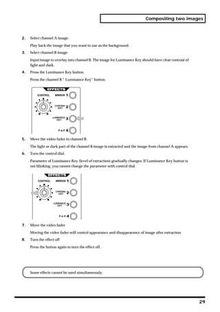
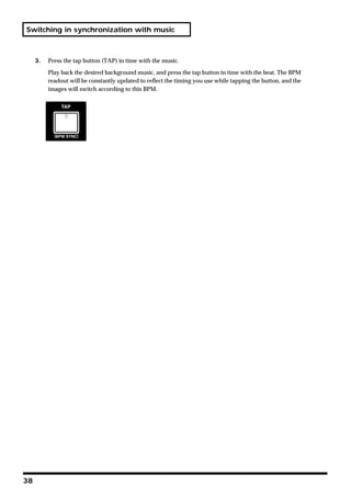
![Checking the inputs and outputs
3. Switch the output channel
Try switching the channel that is being output to the V-4’s preview monitor. Press the preview
select buttons (1 through 4 and OUTPUT) one after another, and verify that the image being output
to your TV monitor changes accordingly.
About the display on preview monitor
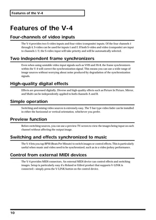
Information about settings of V-4 is displayed to the Preview Monitor as below.
Selection of preview output
Current position and
Settings of setting of Output Fader
BPM and TAP
Settings of Settings of
channel A effects channel B effects
Selection of
Transition Effect Channel selection
of video fader and
Setting of input selection
Transformers
• If name of the effect is highlighted, this is the effect selected
• If * mark is displayed after effect name, the effect parameter can be changed with the control dial.
• If ball mark is displayed aside highlighted effect names, it means the effect parameter can be changed
with the control dial.
You can add or reduce the information displayed on the preview monitor by changing the settings
of the V-4 as described on P. 75 or later.
• [**Preset**] is displayed when position 1 of Memory Dial is selected. The 1st setting is fixed to the
factory preset and cannot be changed.
• [*Protect On*] is displayed when Memory Protection is enabled. If this message appears, settings
cannot be changed.
21](https://image.slidesharecdn.com/v-4manual-110628090020-phpapp02/85/Roland-V-4-21-320.jpg)


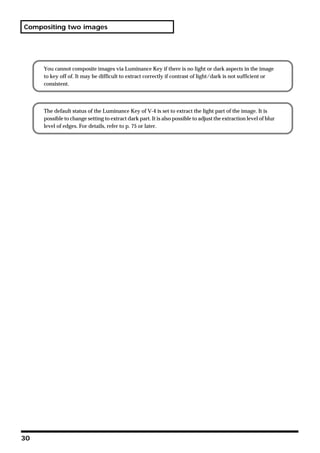


![Editing the front panel assignments
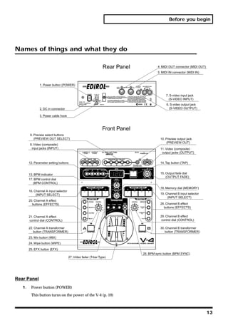
Changing the assignment of the mix button (MIX)
With the factory settings, mix (MIX: dissolve) is assigned to this button for all eight positions of the
memory dial. Here’s how to assign a different type of transition effect to the mix button for one of
the dial positions.
1. Set the memory dial to the number whose settings you want to change.
Set the memory dial to the number (2 through 8) whose settings you want to change.
2. Press the mix button(MIX)
The button lights up when pressed.
3. Press the menu button (MENU).
Press the menu button (MENU) located in the upper left of the panel. The settings edit menu will
appear on the TV screen connected to the preview output.
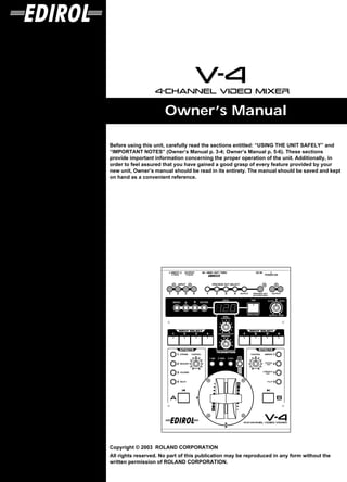
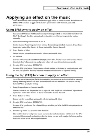
4. Select “MIX.”
Use the cursor buttons to select “Mix (Trans1).” It will blink when you select it. The memory dial
number you select is displayed following “Mix (Trans1).” If you have selected memory number 2,
this will indicate [Mem2].
5. Press the enter button (ENTER).
Press the enter button (located at the right of the cursor buttons) to make your selection. The
preview screen display will change.
42](https://image.slidesharecdn.com/v-4manual-110628090020-phpapp02/85/Roland-V-4-42-320.jpg)
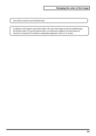
![Editing the front panel assignments
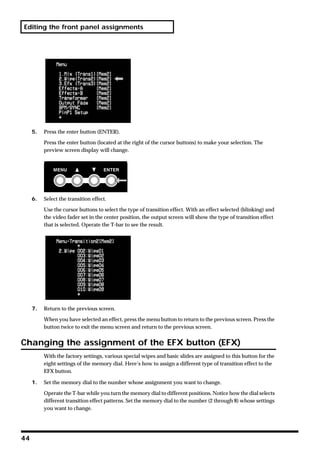
6. Select the transition effect.
Use the cursor buttons to select the type of transition effect. With an effect selected (blinking) and
the video fader set in the center position, the output screen will show the type of transition effect
that is selected. Operate the video fader to see the result.
7. Return to the previous screen.
When you have selected an effect, press the menu button to return to the previous screen. Press the
button twice to exit the menu screen and return to the previous screen.
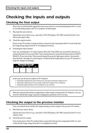
Changing the assignment of the wipe button (WIPE)
With the factory settings, eight basic wipes are assigned to this button for the eight settings of the
memory dial. Here’s how to assign a different type of transition effect to the wipe button.
1. Set the memory dial to the number whose assignment you want to change.
Operate the video fader while you turn the memory dial to different positions. Notice how the dial
selects different wipe patterns. Set the memory dial to the number (2 through 8) whose settings you
want to change.
2. Press the wipe button (WIPE)
The button lights up when pressed.
3. Press the menu button (MENU).
Press the menu button (MENU) located in the upper left of the panel. The settings edit menu will
appear on the TV screen connected to the preview output.
4. Select “WIPE.”
Use the cursor buttons to select “WIPE.” It will blink when you select it. The memory dial number
you select is displayed following “WIPE (Trans1).” If you have selected memory number 2, this
will indicate [Mem2].
43](https://image.slidesharecdn.com/v-4manual-110628090020-phpapp02/85/Roland-V-4-43-320.jpg)
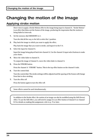
![Editing the front panel assignments
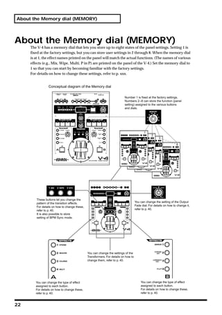
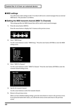
2. Press the EFX button (EFX)
The button lights up when pressed.
3. Press the menu button (MENU).
Press the menu button (MENU) located in the upper left of the panel. The settings edit menu will
appear on the TV screen connected to the preview output.
4. Select “EFX.”
Use the cursor buttons to select “EFX.” It will blink when you select it. The memory dial number
you select is displayed following “EFX.” If you have selected memory number 2, this will indicate
[Mem2].
5. Press the enter button (ENTER).
Press the enter button (located at the right of the cursor buttons) to make your selection. The
preview screen display will change.
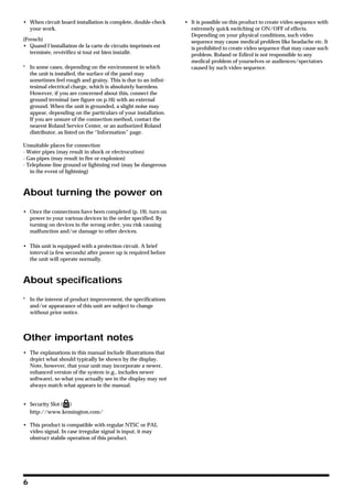
6. Select the transition effect.
Use the cursor buttons to select the type of transition effect. With an effect selected (blinking) and
the video fader set in the center position, the output screen will show the type of transition effect
that is selected. Operate the T-bar to see the result.
45](https://image.slidesharecdn.com/v-4manual-110628090020-phpapp02/85/Roland-V-4-45-320.jpg)
![Editing the front panel assignments
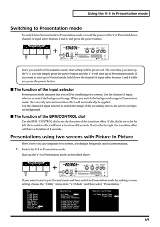
7. Return to the previous screen.
When you have selected an effect, press the menu button to return to the previous screen. Press the
button twice to exit the menu screen and return to the previous screen.
Changing the assignment of the output fade dial
(OUTPUT FADE)
With the factory settings, and when the memory dial is set to number 1, turning the output fade
dial toward the left will fade-to-black, and turning it toward the right will fade-to-white.
1. Set the memory dial to the number whose assignment you want to change.
Operate the output fade dial while you turn the memory dial to different positions. Set the memory
dial to the number (2 through 8) whose settings you want to change.
2. Press the menu button (MENU).
Press the menu button (MENU) located in the upper left of the panel. The settings edit menu will
appear on the TV screen connected to the preview output.
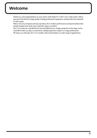
3. Select “Output Fade”.
Use the cursor buttons to select “Output Fade.” It will blink when you select it. The memory dial
number you select is displayed following “Output Fade.” If you have selected memory number 2,
this will indicate [Mem2].
46](https://image.slidesharecdn.com/v-4manual-110628090020-phpapp02/85/Roland-V-4-46-320.jpg)

![Editing the front panel assignments
Changing the assignments of the channel A and B effect
buttons (EFFECTS)
With the factory settings, effect buttons 1 through 4 of channels A and B are assigned the following
effects:
Channel A: 1 Strobe (STROBE)
2 Negative (NEGATIVE)
3 Colorize (COLORIZE)
4 Multi (MULTI)
Channel B: 1 Mirror (MIRROR)
2 Chroma key (CHROMA KEY)
3 Luminance key (LUMINANCE KEY)
4 Picture in picture (PinP)
1. Turn the memory dial.
Turn the memory dial to the number (2 through 8) whose assignment you want to change.
2. Choose the effect button whose assignment you want to change.
Press the effect button (channel A buttons 1-4, channel B buttons 1-4) whose assignment you want
to change. The effect will be applied.
3. Press the menu button (MENU).
Press the menu button (MENU) located in the upper left of the panel. The settings edit menu will
appear on the TV screen connected to the preview output.
4. Select either “Effects-A” or “Effects-B.”
Select “Effects-A” if you want to edit the channel A settings. Select “Effects-B” if you want to edit
the channel B settings. Use the cursor buttons to make your selection. The selection will blink. The
memory dial number you select is displayed following “Effects-A” or “Effects-B.” If you have
selected memory number 2, this will indicate [Mem2].
48](https://image.slidesharecdn.com/v-4manual-110628090020-phpapp02/85/Roland-V-4-48-320.jpg)

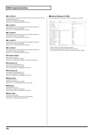
![Editing the front panel assignments
If you select an effect with the “*” mark after the effect name, the effect value can be changed with
the control dial.
8. Return to the previous screen.
When you have made your selection, press the menu button to return to the previous screen. Press
the button three times to exit the menu screen and return to the previous screen.
Changing the assignment of the BPM sync button (BPM
SYNC)
With the factory settings, and when the memory dial is set to 1, BPM sync is set to switch between
A and B by using a transition effect. The transition speed will be the BPM shown in the BPM
indicator.
1. Turn the memory dial.
Select the memory number (2 through 8) whose assignments you want to change.
2. Press the menu button (MENU).
Press the menu button (MENU) located in the upper left of the panel. The settings edit menu will
appear on the TV screen connected to the preview output.
3. Select “BPM/SYNC.”
Use the cursor buttons to select “BPM/SYNC.” The memory dial number you select is displayed
following “BPM/SYNC.” If you have selected memory number 2, this will indicate [Mem2].
4. Press the enter button (ENTER)
Press the enter button to proceed to the setting screen.
50](https://image.slidesharecdn.com/v-4manual-110628090020-phpapp02/85/Roland-V-4-50-320.jpg)

![Editing the front panel assignments
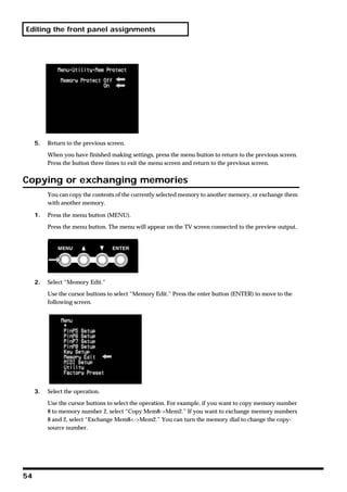
3. Select “Transformer.”
Use the cursor buttons to select “Transformer.” The memory dial number you select is displayed
following “Transformer.” If you have selected memory number 2, this will indicate [Mem2].
4. Press the enter button (ENTER).
Press the enter button (located at the right of the cursor buttons) to make your selection. The
preview screen display will change to a screen where you can choose the parameter to be assigned.
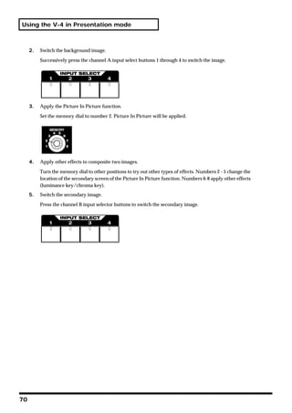
5. Select a pattern.
Select a pattern from the range of “01: none-none” to “36: Black-White.” If you select “01: none-
none,” the transformer buttons will have no effect; you will not be able to switch between images
A/B or fade to white/black by pressing these buttons. For details on the operation and times of
these parameters, refer to the menu list on p. 78.
6. Return to the previous screen.
When you have finished making the settings, press the menu button to return to the previous
screen. Press the button twice to exit the menu screen and return to the previous screen.
52](https://image.slidesharecdn.com/v-4manual-110628090020-phpapp02/85/Roland-V-4-52-320.jpg)

![Editing the front panel assignments
4. Press the enter button (ENTER).
When you have specified the operation, press the enter button. The display will indicate “Push
[ENTER]” so press the enter button once again. The selected operation will be executed.
5. Return to the previous screen.
After you have executed the operation, press the menu button to return to the previous screen.
Press the button twice to exit the menu screen and return to the previous screen.
Recalling the factory settings
You can recall factory settings with the following operation. Any change of settings or adjustments
you have made will be cleared with this operation. Do not execute this function if you want to
retain any of your saved settings. If it is necessary to execute the recall function, you should write
down the settings of your memory first.
1. Press the menu button (MENU).
Press the menu button. The menu will appear on the TV screen connected to the preview output.
2. Select “Factory Preset.”
Use the cursor buttons to select “Factory Preset.” Press the enter button (ENTER) to move to the
following screen.
3. Select “Yes[ENTER]SW.”
Use the cursor buttons to select “ Yes[ENTER]SW.”
55](https://image.slidesharecdn.com/v-4manual-110628090020-phpapp02/85/Roland-V-4-55-320.jpg)


![Calibrating the video fader
Calibrating the video fader
With the factory settings, moving the V-4’s video fader all the way to the A position will output
100% of channel A, and moving it all the way to the B position will output 100% of channel B. If for
some reason, moving the video fader all the way to A or B does not output 100% of the image, you
can use the following procedure to automatically calibrate the fader.
1. Move the video fader all the way to the A position.
First you will calibrate the channel A setting. Move the video fader all the way to the A position.
2. Press the menu button (MENU).
Press the menu button to display the menu in the preview screen.
3. Select “Utility.”
Use the cursor buttons to select “Utility.” Then press the enter button to display the “Utility”
settings.
4. Select “Video Fader Calibrate A.”
Use the cursor buttons to select “Video Fader Calibrate A.” The display will indicate “V Fader [A]
set [ENTER] SW.”
5. Press the enter button (ENTER).
Press the enter button. The channel A position will be calibrated automatically.
6. Move the video fader all the way to the B position.
Next, you will calibrate the channel B setting. Move the video fader all the way to the B position.
66](https://image.slidesharecdn.com/v-4manual-110628090020-phpapp02/85/Roland-V-4-66-320.jpg)
![Calibrating the video fader
7. Press the menu button (MENU).
Press the menu button to display the menu in the preview screen.
8. Select “Utility.”
Use the cursor buttons to select “Utility.” Then press the enter button to display the “Utility”
settings.
9. Select “Video Fader Calibrate B.”
Use the cursor buttons to select “Video Fader Calibrate B.” The display will indicate “V Fader [B]
set [ENTER] SW.”
10. Press the enter button (ENTER).
Press the enter button. The channel B position will be calibrated automatically.
11. Return to the previous screen.
When you are finished, press the menu button to return to the previous screen. If you press the
menu button twice, you will exit the menu screens and return to the previous screen.
67](https://image.slidesharecdn.com/v-4manual-110628090020-phpapp02/85/Roland-V-4-67-320.jpg)


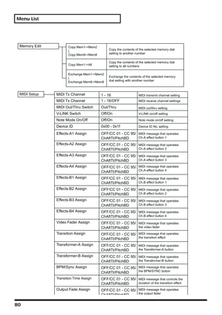
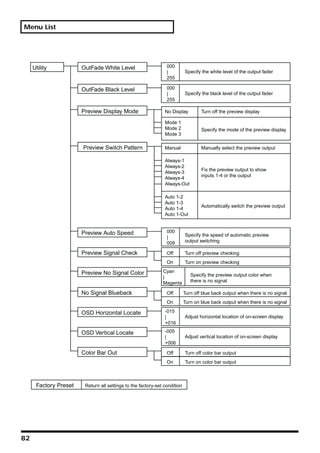
![Menu List
Menu List
Mix (Trans1) [Mem2-8] 001:Mix Mix(Dissolve)
Wipe (Trans2) [Mem2-8] 002:Wipe01
| Hard-edged wipes
Efx (Trans3) [Mem2-8]
073:Wipe72
074:SWipe01
| Soft-edged wipes
145:SWipe72
146:MWipe01
| Multi-border wipes
217:MWipe72
218:Key01 Transition effects
| using key extraction
221:Key04
222:Slide01
| Slide in/out
248:Slide27
Parameter of effects marked by an asterisk* can be varied by the control dial
Effects-A [Mem2-8] A-Efx1 01:STILL1 Still
A-Efx2 02:STILL2
A-Efx3 03:STROBE1
| Strobe
A-Efx4 12:STROBE
Effects-B [Mem2-8] B-Efx1 13:SHAKE1
| Shake
B-Efx2 16:SHAKE4
B-Efx3
17:NEGATIVE1
B-Efx4 | Negative (inverted
20:NEGATIVE brightness and color)
21:COLRIZE1
| Colorize (apply colors
29:COLRIZE to the image)
30:MONOCOLOR1
| Monochrome color filter
38:MONOCOLOR
39:POSTERIZE1 Posterize (vary the
| brightness gradations)
43:POSTERIZE
44:COLORPASS1 Make monochrome while
| leaving one color
52:COLORPASS (color pass)
53:W-LUMIKEY Luminance key
54:W-LUMIKEY (extract white)
55:B-LUMIKEY Luminance key
56:B-LUMIKEY (extract black)
75](https://image.slidesharecdn.com/v-4manual-110628090020-phpapp02/85/Roland-V-4-75-320.jpg)
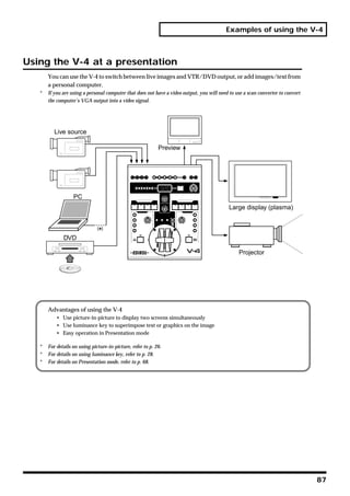
![Menu List
Parameter of effects marked by an asterisk* can be varied by the control dial
Effects-A [Mem2-8] A-Efx1
57:CHROMAKEY Chroma key
A-Efx2 58:CHROMAKEY
A-Efx3
59:MULTI-H1 Horizontally divided
A-Efx4 | multiscreen
63:MULTI-H
Effects-B [Mem2-8] B-Efx1
B-Efx2 64:MULTI-V1 Vertically divided
| multiscreen
B-Efx3 68:MULTI-V
B-Efx4
69:MULTI-HV1 Horizontally and vertically
| divided multiscreen
73:MULTI-HV
74:MIRROR-H1
| Horizontal mirroring
78:MIRROR-H
79:MIRROR-V1
| Vertical mirroring
83:MIRROR-V
84:MIRROR-HV1
| Horizontal and vertical
88:MIRROR-HV mirroring
White-LumiKey Level 000
Adjust the level of luminance
| key extraction (extract white)
255
White-LumiKey Edge 001
Adjust the edge blurring for
| luminance key (extract white)
015
Black-LumiKey Level 000
Adjust the level of luminance
| key extraction (extract black)
255
Black-LumiKey Edge 001
Adjust the edge blurring for
| luminance key (extract black)
015
ChromaKey Color Blue-Magenta
Specify the color for
| chroma key
Yellow-Red
ChromaKey Level 000
Adjust the level of chroma
| key extraction
255
ChromaKey Edge 001
Adjust the edge blurring for
| chroma key
015
76](https://image.slidesharecdn.com/v-4manual-110628090020-phpapp02/85/Roland-V-4-76-320.jpg)
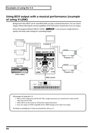
![Menu List
Effects-A [Mem2-8] A-Efx1
89:PinP-1
A-Efx2 | Picture In Picture
96:PinP-8
A-Efx3
A-Efx4
Effects-B [Mem2-8] B-Efx1
B-Efx2
B-Efx3
B-Efx4
PinP1-8 HPosi HPosi 000
| Adjust horizontal location of PinP
HPosi 153
PinP1-8 VPosi VPosi 000
| Adjust vertical location of PinP
VPosi 207
PinP1-8 4:3 HVSize 4:3 HVSize 000
Adjust size at fixed aspect ratio
|
of 4 (horizontal) :3 (vertical)
4:3 HVSize 110
PinP1-8 HSize HSize 000
| Adjust horizontal size of PinP
HSize 110
VSize 000
PinP1-8 VSize
| Adjust vertical size of PinP
VSize 220
PinP1-8 Border Border 000
| Select border width of PinP
Border 015
PinP1-8 BColor BColor 000
| Select border color of PinP
BColor 015
PinP1-8 Shadow Shadow 000
| Select distance of PinP shadow
Shadow 015
PinP1-8 SColor SColor 000
| Select color of PinP shadow
SColor 015
77](https://image.slidesharecdn.com/v-4manual-110628090020-phpapp02/85/Roland-V-4-77-320.jpg)
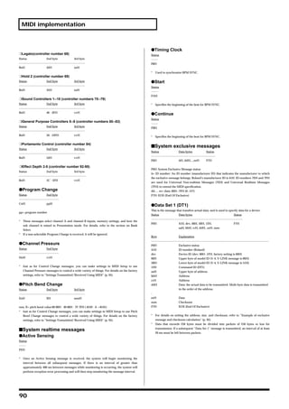
![Menu List
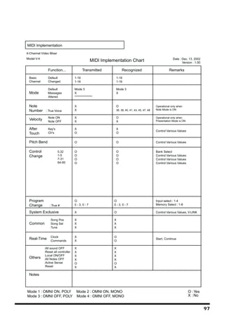
Transformer [Mem2-8] 01:none-none No function
02:Trans-Trans Output the image of pressed channel as long as button is held.
03:A<->9-9<->B
04:A<->8-8<->B
05:A<->7-7<->B
06:A<->6-6<->B
Switch between A and B each time you press the button.
07:A<->5-5<->B 0--9 indicates the duration of the transition.
08:A<->4-4<->B Higher numbers produce a longer transition.
09:A<->3-3<->B
10:A<->2-2<->B
11:A<->1-1<->B
12:A<->0-0<->B
13:A<-9 - 9->B
14:A<-8 - 8->B
15:A<-7 - 7->B
16:A<-6 - 6->B Switch to the image of the channel (A or B) you press.
17:A<-5 - 5->B 0--9 indicates the duration of the transition.
Higher numbers produce a longer transition.
18:A<-4 - 4->B
19:A<-3 - 3->B
20:A<-2 - 2->B
21:A<-1 - 1->B
22:A<-0 - 0->B
23:A->9 - 9<-B
24:A->8 - 8<-B
25:A->7 - 7<-B
26:A->6 - 6<-B Switch to the image of the opposite channel (A or B)
from the one you press.
27:A->5 - 5<-B
0--9 indicates the duration of the transition.
28:A->4 - 4<-B Higher numbers produce a longer transition.
29:A->3 - 3<-B
30:A->2 - 2<-B
31:A->1 - 1<-B
32:A->0 - 0<-B
33:White-White Fade both channels to white
34:Black-Black Fade both channels to black
35:White-Black Fade channel A to white/channel B to black
36:Black-White Fade channel A to black/channel B to white
Output Fade [Mem2-8] 01:No Control No function
02:Black-White Left: black/Right: fade to white
03:AutoB/W Auto fade
78](https://image.slidesharecdn.com/v-4manual-110628090020-phpapp02/85/Roland-V-4-78-320.jpg)
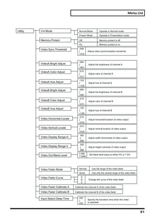
![Menu List
BPM Sync [Mem 2-8] Mode Direct A-B Transition by cut
Select BPM sync mode TransitionA-B Transition applying effect
Speed BPMx1/4 Transition at 1/4 speed of BPM
BPMx1/2 Transition at 1/2 speed of BPM
Specify BPM sync speed
BPMx1 Transition at speed of BPM
BPMx2 Transition at double speed of BPM
PinP1 Setup PinP1-8 HPosi HPosi 000
| Adjust horizontal location of PinP
PinP2 Setup HPosi 153
PinP3 Setup
PinP1-8 VPosi VPosi 000
PinP4 Setup | Adjust vertical location of PinP
PinP5 Setup VPosi 207
PinP6 Setup PinP1-8 4:3 HVSize 4:3 HVSize 000
Adjust size at fixed aspect ratio
|
PinP7 Setup of 4 (horizontal) :3 (vertical)
4:3 HVSize 110
PinP8 Setup PinP1-8 HSize HSize 000
| Adjust horizontal size of PinP
HSize 110
PinP1-8 VSize VSize 000
| Adjust vertical size of PinP
VSize 220
PinP1-8 Border Border 000
| Select border width of PinP
Border 015
PinP1-8 BColor BColor 000
| Select border color of PinP
BColor 015
PinP1-8 Shadow Shadow 000
| Select distance of PinP shadow
Shadow 015
PinP1-8 SColor SColor 000
| Select color of PinP shadow
SColor 015
Key Setup 000
White-LumiKey Level Adjust the level of luminance
|
255 key extraction (extract white)
White-LumiKey Edge 001
| Adjust the edge blurring for
015 luminance key (extract white)
Black-LumiKey Level 000
| Adjust the level of luminance
255 key extraction (extract black)
001
Black-LumiKey Edge Adjust the edge blurring for
|
015 luminance key (extract black)
ChromaKey Color Blue-Magenta
| Specify the color for
Yellow-Red chroma key
ChromaKey Level 000 Adjust the level of chroma
|
key extraction
255
001
ChromaKey Edge Adjust the edge blurring for
|
chroma key
015
79](https://image.slidesharecdn.com/v-4manual-110628090020-phpapp02/85/Roland-V-4-79-320.jpg)


The document is an owner's manual that provides important safety instructions and notes about operating the unit. It warns the user to read sections on safe use and important notes before operating the unit. Additionally, it recommends reading the entire manual to understand all features and keeping it handy for future reference. The manual contains over 150 safety rules, warnings, and precautions about installation, use, maintenance and technical specifications of the unit.