SlideShare a Scribd company logo
1 of 12
Download to read offline
Fan-coil valves
                          Series 2131 - 3131 - 4131


Main features

Complete range in the following versions :   - The 3-way version and the 3-way versions with
                                               4 ports can be used as diverting or mixing valves
• 2-way - DN: 1/2”, 3/4”, 1”                   of compact size and reduced weights.
• 3-way - DN: 1/2”, 3/4”, 1”                   The valves are motorized with actuators series
• 3-way with 4 ports - DN: 1/2”, 3/4”          22C or actuators with stroke 2.5 mm with
                                               ring nut M30x1.5.
FAN-COIL VALVES


    Description
    Fan-coil control valves series 2131, 3131, 4131 are used for controlling the flow of hot or cold water in heating
    and air conditioning systems. They are operated by electric actuators with max. stroke of 2.5 mm. such as
2   electrothermic actuator series 22C.

    As standard, the valves are available in the configuration with male thread in the following versions :

    • 2-way series 2131
    • 3-way series 3131
    • 3-way with 4 ports series 4131 with built-in by-pass.

    Operation of the valve plug is by electrothermic actuator series 22C, available in the following versions:

    • NO (normally open) 2-wire(Standard) or 4-wire (with auxiliary microswitch contact)
    • NC (normally closed) 2-wire (Standard) or 4-wire (with auxiliary microswitch contact)

    All actuators of the 22C series can easily be fastened to the valve body with a threaded ring nut. (M30x1.5).


                                   2131
                                    Two-way brass valve for fan-coils.
                                    ON/OFF operation with actuators series 22C.
                                    Max. operating temperature: 100°C. Disc stroke: 2.5 mm.
                                    Nominal pressure: 16 bar.
                                     Type            Part number           Dn                 Kvs             Weight (g)
                                     2131            213112                1/2" MM            1,7             200
                                     2131            213134                3/4" MM            2,8             200
                                     2131            21311                 1" MM              4,5             500


                                   3131
                                    Three-way brass valve for fan-coils. ON/OFF operation with actuators series 22C.
                                    Max. operating temperature: 100°C. Disc stroke: 2.5 mm. Can be used both as
                                    mixing and diverting valve, except for version 31311 which can only be used as
                                    diverting valve. Nominal pressure: 16 bar.

                                    The Kvs and by-pass Kvs values given in the table alongside refer to the valve
                                    used for diverting service.


                                     Type       Part number      Dn             Kvs         Kvs By-bass       Weight (g)
                                     3131       313112           1/2" MM        1,7         1,3               200
                                     3131       313134           3/4" MM        2,8         1,8               250
                                     3131       31311            1" MM          4,5         3,1               550


                                   VU
                                    Tee fitting for creating by-pass in valves series 3131 (Dn 1“).


                                     Type                 Part number                   Dn                    Weight (g)
                                     VU                   VU311                         1" MM                 250
FAN-COIL VALVES


                                4131
                                Three-way brass valve with 4 connections for fan-coils. ON/OFF operation with
                                actuators series 22C. Max. operating temperature: 100°C. Disc stroke: 2.5 mm.
                                Can be used both as mixing and diverting valve. Nominal pressure: 16 bar.               3

                                The Kvs and by-pass Kvs values given in the table alongside refer to the valve
                                used for diverting service.


                                 Type       Part number        Dn            Kvs       Kvs By-bass       Weight (g)
                                 4131       413112             1/2" MM       1,7       1,3               350
                                 4131       413134             3/4" MM       2,8       1,8               400


                                840
                                Soft sealed union with nut for zone valves series 2131, 3131, 4131.


                                 Type             Part number                 Dn                         Weight (g)
                                 840              8401212GAS                  1/2" x 1/2"                50
                                 840              8403434GAS                  3/4" x 3/4"                50
                                 840              84011GAS                    1" x 1"                    50


Application
The valves are used for shutting off (series 2131, two-way) or diverting/mixing (series 3131 - 4131, 3-way and
3-way with 4 ports size 1/2” e 3/4”), the heat transfer fluid to a heating or air conditioning system as required by
the room thermostat (or timing thermostat).

The 3-way fan-coil valves series 3131 or 3-way with 4 ports series 4131, thanks to the special configuration of
the plug controlling the by-pass flow, can be used equally well as diverting or mixing valves (thus optimizing to the
full the various plumbing requirements in assembly).


 Diverting
                                                 AB               A


                                                            B


 Mixing


                                                           B


                                                 AB              A
FAN-COIL VALVES


    Operation
    Operation of the fan-coil control valves 2131,3131,4131 is through the movement of the plug which shuts off the
    heat transfer fluid: the ON/OFF action of the plug is controlled by the actuator series 22C whose internal motor
4
    consists of a wax thermostatic element activated by a PTC thermistor against a signal sent by a room thermostat
    (or timing thermostat). The electrochemical actuator series 22C, in the 4-wire version, is provided with an
    auxiliary contact for additional controls (metering, control of pumps, fans or other equipment). The mechanical
    characteristic of the valves is of the Normally Open type. It can be adjusted or fully closed by manually turning the
    threaded plastic cap, provided on the valve. This threaded cap acts directly on the valve stem.

    When coupled to the 22C NC actuator, under rest conditions (actuator not energized), the valve becomes

    • normally closed (NC) (straight way closed and by-pass open if 3-way type); when the actuator is energized,
      the valve is opened.

    When coupled to the 22C NA actuator, under rest conditions (actuator not energized), the valve remains

    • normally open (NO) (straight way open and by-pass closed if 3-way type); when the actuator is energized,
      the valve is closed.

    The hydraulic flow rate and pressure drops characteristics of the valves are given in appropriate charts; instead,
    when coupled with the ON/OFF actuators, they assume the characteristics associated with such device.

    The three-way valves (or three-way valves with 4 ports) are designed and built to be used both as diverting valves
    (one inlet and two outlets) and mixing valves (two inlets and one outlet). It is recommended to observe the
    operating Pmax given in the table in order to avoid risk of malfunctions and/or noise.

    The reliability of the fan-coil control valves 2131, 3131, 4131 is guaranteed by the 100% testing on the
    production, which checks the hydraulic seals of the valve body and its components towards the outside and the
    seal of the plug in its flow shut-off function.


    Design features
    Body                                                                            Brass CW617N
    Stem                                                                            Brass with chemical nickel-plating
    Spring                                                                          Stainless steel
    Plug rubber                                                                     EPDM


    Technical features common to the entire range
    Max pressure, models w. constant Kv                                                 16 bar
    Max pressure, models w. variable Kv                                                 10 bar
    Min. fluid temperature                                                              4°C
    Max. fluid temperature                                                              110°C
    Liquids which can be used                                                          Water (with glycol 50%)
    Plug stroke                                                                        2.5 mm
    By-pass leakage                                                                       0,02 % Kvs
    Actuator connection                                                                Threaded ring nut M30 x 1.5


    Installation
    Choice of the fan-coil control valves depends on the type of plumbing systems as well as the required flow rate
    and pressure drop characteristics.
    In systems with 2-way control valves it is advisable to provide by-pass valves series 466 to ensure a minimum
    recirculation of the fluid.
    Before mounting the valves, make sure that the piping is clean, and free from welding slag or the like.

    It is recommended not to install the valve with the 22C actuator facing down.

    The valves can be connected by using the soft-sealed tailpieces series 840 with the range of single-piece
    or union fittings (3-piece).

    The 1” three-way valves can use the TEE fitting (part No. VU311 - DN 1”) for making the by-pass.
FAN-COIL VALVES


Hydraulic characteristics


                                                  Pre-setting (Kv adjustable)


                                                                                             Max. operation pressure


                                                                                                                                                                Close off with actuator


                                                                                                                                                                                                                                    Close off with actuator
                                                                                                                                                                                                                                                              5


                                                                                                                                          operation pressure.


                                                                                                                                                                                                              operation pressure.
         Valve part number


                                                                                                                                           (noise < 38 dBA)


                                                                                                                                                                                                               (noise < 38 dBA)
                                                                                                                                            Max. differential


                                                                                                                                                                                                                Max. differential
                                                                                                                                                                     22C NO/NC


                                                                                                                                                                                                                                         22C NO/NC
                                                                                                                             Kv by-pass


                                                                                                                                                                                                 Kv by-pass
                              DN Inches


                                                                                 Port size


                                                                                                    PN [bar]
                                          DN mm


                                                                                                                                                 Pmax


                                                                                                                                                                                                                     Pmax
                                                                                                                                                  [bar]


                                                                                                                                                                          [bar]


                                                                                                                                                                                                                      [bar]


                                                                                                                                                                                                                                              [bar]
                                                                                                                       Kvs


                                                                                                                                                                                          Kvs
                                                                                                                                                                            Ps


                                                                                                                                                                                                                                                Ps
    2 WAY VALVES
    213112     1/2"                       15                                    15A2            16                     1,7    -                0,8                   2,5                   -        -                -                     -
    213112P    1/2"                       15                                    15F2            16                     1,7    -                0,8                   2,5                   -        -                -                     -
    213112DP   1/2"                       15                                    15A2                                   1,7    -                0,8                    4                    -        -                -                     -
    213134     3/4"                       20                                    20A2            16                     2,8    -                0,7                   1,5                   -        -                -                     -
    213134P    3/4"                       20                                    20F2            16                     2,6    -                0,7                   1,5                   -        -                -                     -
    213134DP   3/4"                       20                                    20A2            16                     2,8    -                0,7                    4                    -        -                -                     -
    21311       1"                        25                                    25A2            16                     4,5    -                0,6                   0,7                   -        -                -                     -
    21311P      1"                        25                                    25F2            16                     4,5    -                0,6                   0,7                   -        -                -                     -
    21311DP     1"                        25                                    25A2            16                     4,5    -                0,6                    4                    -        -                -                     -

    3 WAY VALVES                                                                                                        Used as DIVERTER VALVE    Used as MIXING VALVE
    313112     1/2"                       15                                    15A3            16                     1,7 1,3    0,8     2,5  1,7 1,2    0,7        2
    313112P    1/2"                       15                                    15F3            16                     1,7 1,3    0,8     2,5  1,7 1,2    0,7        2
    313112DP   1/2"                       15                                    15A3            16                     1,7 1,3    0,8      4   1,7 1,2    0,7        4
    313134     3/4"                       20                                    20A3            16                     2,8 1,8    0,7     1,5  2,5 1,6    0,5        1
    313134P    3/4"                       20                                    20F3            16                     2,8 1,8    0,7     1,5  2,5 1,6    0,5        1
    313134DP   3/4"                       20                                    20A3            16                     2,8 1,8    0,7      4   2,5 1,6    0,5        1
    31311       1"                        25                                    25A3            16                     4,5 3,1    0,6     0,7  4,5 3,1    0,4       0,7
    31311P      1"                        25                                    25F3            16                     4,5 3,1    0,6     0,7  4,5 3,1    0,4       0,7
    31311DP     1"                        25                                    25A3            16                     4,5 3,1    0,6      4   4,5 3,1    0,4        4

    3 WAY VALVES 4 PORT                                                                                                 Used as DIVERTER VALVE                                                  Used as MIXING VALVE
    413112                   1/2"         15                                    15A4            16                     1,7   1,3               0,8                   2,5                  1,7    1,2               0,7                     2
    413112P                  1/2"         15                                    15F4            16                     1,7   1,3               0,8                   2,5                  1,7    1,2               0,7                     2
    41311240P                1/2"         15                                    15I4            16                     1,7   1,3               0,8                   2,5                  1,7    1,2               0,7                     2
    413112DP                 1/2"         15                                    15A4            16                     1,7   1,3               0,8                    4                   1,7    1,2               0,7                     4
    413134                   3/4"         20                                    20A4            16                     2,8   1,8               0,7                   1,5                  2,5    1,6               0,5                     1
    413134P                  3/4"         20                                    20F4            16                     2,6   1,8               0,7                   1,5                  2,5    1,6               0,5                     1
    413134DP                 3/4"         20                                    20A4            16                     2,8   1,8               0,7                    4                   2,5    1,6               0,5                     4
    41313440P                3/4"         20                                    20I4            16                     2,8   1,8               0,7                   1,5                  2,5    1,6               0,5                     1


• Red part numbers are standard versions


• KVs = nominal value of the flow in the main way of the valve in m3/h with the valve fully open at a pressure of
  1 bar and with water temperature at 20 °C

•      Pmax = maximum dynamic differential pressure at the ends of the fully open valve, without risk of noise
     ( < 38 dBA)

•      Ps= maximum static differential pressure at the ends of the valve against which the valve is able to be opened
     (through its internal spring for the three-way versions; through the actuator for the two-way versions)
FAN-COIL VALVES


    Overall dimensions (mm)


6   2131                                                         3131


                                                                                                     C
                                     C


                                                                                                     B
                                     D
                                     B


                                                                                                            D
                                                                     DN
       DN


                         A
                                                                                            A
    Part number   DN     A    B          C         D             Part number   DN          A    B    C      D
    213112        1/2”   52   29         13,5      51            313112        1/2”        52   29   13,5   68,5
    213112P       1/2”   52   29         13,5      51            313112P       1/2”        52   29   13,5   68,5
    213112DP      1/2”   52   29         13,5      51            313112DP      1/2”        52   29   13,5   68,5
    213134        3/4”   56   28         13,5      56            313134        3/4”        56   28   13,5   69,5
    213134P       3/4”   56   28         13,5      56            313134P       3/4”        56   28   13,5   69,5
    213134DP      3/4”   56   28         13,5      56            313134DP      3/4”        56   28   13,5   69,5
    21311         1”     82   30,5       13,5      77,5          31311         1”          82   38   13,5   92,5
    21311P        1”     82   30,5       13,5      77,5          31311P        1”          82   38   13,5   92,5
    21311DP       1”     82   30,5       13,5      77,5          31311DP       1”          82   38   13,5   92,5


                                 4131
                                                                         B C
                                     DN


                                                                               D
                                                                         E


                                                            A

                               Part number      DN     A    B     C        D          E
                               413112           1/2”   52   29    13,5     95,5       35
                               413112P          1/2”   52   29    13,5     95,5       35
                               413112DP         1/2”   52   29    13,5     95,5       35
                               41311240P        1/2”   52   29    13,5     100,5      40
                               41313440P        3/4”   56   28    13,5     102,5      40
                               413134           3/4”   56   28    13,5     112,5      50
                               413134P          3/4”   56   28    13,5     112,5      50
                               413134DP         3/4”   56   28    13,5     112,5      50
FAN-COIL VALVES


Connections dimensions (mm)


15F2                                                                          15A2                                                          7


                                                                                              Ø14.5 +0.1
                              Ø13.8 +0.1


                                                                                                     0
                                     0


                                                                                                                45°


                                                                                      G1/2
              G 1/2


                                                                                                            1.5
                                                                                                                                    12.7
                                                       10   17.2                                                      10


20F2                                                                          20A2
                                                                                                °
                                                                                             45
                                                                                             Ø20.5
                                                                                    G 3/4
     G 3/4

                      Ø19.5


                                                                                                            1.5
                                                                                                                                    14.5
                                                    12.5     18                                                       10


25A2                                                                          25F2


                   1.5


                                                °
                                           45
             Ø26
G1


                                                                              Ø24
                                                                         G1


                                                                  21.5                                     12                        21.5
                                           12
FAN-COIL VALVES


    15A3                                                                          15F3

8
                                  1.5
                 Ø14.5 +0.1
                        0


                                                                                                     Ø13.8 +0.1
                                                                                                            0
                                                                            45°


                                                                                          G 1/2
     G 1/2


                                                                                                                       10                   17.2


                                                 10               12.7


                                                                                                                              15.9
                                                       10


    20A3                                                                          20F3


                                      1.5


                                                                                                                       12.5
                              Ø20.5
         G 3/4


                                                                                                     Ø19.5
                                                                                       G 3/4


                                                 45°              14.5
                                                                                                                                               18
                                                                                                                                     14.1
                                                            9.5


                                                 10


         25A3                                                                     25F3

                      1.5


                                             °
             Ø26
    G1


                                                                                               Ø24
                                                                                  G1


                                        45


                                        12                               21.5                                     12                                21.5
                                                  12


                                                                                                                        12
FAN-COIL VALVES


 15A4                                                                         15F4

                                                   1.5
                       Ø14.5 +0.1
                              0                                                                                                                   9
                                            45°


                                                                                                   Ø13.8 +0.1
                                                                                                          0
         G 1/2


                                                                                        G 1/2
                                                                                                                               17.2
                                                   10        12.7


                                                                         35
                                                                                                                      10


                                                                                                                                       35
                                                   13.5      12.7


15I4                                                                          20A4
                          +0.1
                           0


                                                                                                                1.5
                          Ø13.8


                                                                                                         Ø20.5


                                                                                                                       45°
                                                                                        G 3/4
       G 1/2


                                                          17.2

                                                                                                                       10       14.5


                                                                                                                                        50
                                              10
                                                                    40


                                                                                                                        15      15


20F4                                                                          20I4
                                    Ø19.5
               G 3/4


                                                                                                Ø19.5
                                                                                G 3/4


                                              12.5         18
                                                                                                                                             40
                                                                    50


                                                                                                                  12.5         18
FAN-COIL VALVES


    Flow rate/pressure drop charts

8    2131 - 3131 - 4131                          Straight way Diverting + Mixing Kv 1,7
                                                                                                                                         DN 1/2"

                                                                  by-pass Diverting Kv 1,3


                              [ kPa ]                              by-pass Mixing Kv 1,2                         [ m bar ] [ mm c.a. ]
                                  20                                                                              200             2000


                                  10                                                                              100             1000
                                   8                                                                              80              800


                                   5                                                                              50              500
                                   4                                                                              40              400
                  PRESSURE DROP


                                   3                                                                              30              300


                                   2                                                                              20              200


                                   1                                                                              10              100
                                  0.8


                                  0.5                                                                             5               50


                                  0.3                                                                             3               30

                                  0.2                                                                             2               20


                                  0.1                                                                             1               10
                                        10     20   30      50        100     200   300   500   1000   2000 3000       [ l/h ]


                                                                                                                       [ m3/h ]
                                        0.01   0.02 0.03   0.05       0.1     0.2   0.3   0.5    1      2    3


                                                                            FLOW RATE


     2131 - 3131 - 4131                                             Straight way Diverting Kv 2,8                                        DN 3/4"
                                                                      Straight way Mxing Kv 2,5
                                                                    by-pass Diverting Kv 1,8

                              [ kPa ]                                 by-pass Mixing Kv 1,6                      [ m bar ] [ mm c.a. ]
                                  20                                                                              200             2000


                                  10                                                                              100             1000
                                   8                                                                              80              800


                                   5                                                                              50              500
                                   4                                                                              40              400
                  PRESSURE DROP


                                   3                                                                              30              300


                                   2                                                                              20              200


                                   1                                                                              10              100
                                  0.8


                                  0.5                                                                             5               50


                                  0.3                                                                             3               30

                                  0.2                                                                             2               20


                                  0.1                                                                             1               10
                                        10     20   30      50        100     200   300   500   1000   2000 3000       [ l/h ]


                                                                                                                       [ m3/h ]
                                        0.01   0.02 0.03   0.05       0.1     0.2   0.3   0.5    1      2    3


                                                                            FLOW RATE
FAN-COIL VALVES


Flow rate/pressure drop charts

 2131 - 3131                                                Straight Way Diverting - Mixing Kv 4,5
                                                                                                                                             DN 1"   9


                             [ kPa ]                                            by-pass Kv 3,1                [ m bar ] [ mm c.a. ]
                                 20                                                                            200             2000


                                 10                                                                            100             1000
                                  8                                                                            80              800


                                  5                                                                            50              500
                                  4                                                                            40              400
                 PRESSURE DROP


                                  3                                                                            30              300


                                  2                                                                            20              200


                                  1                                                                            10              100
                                 0.8


                                 0.5                                                                           5               50


                                 0.3                                                                           3               30

                                 0.2                                                                           2               20


                                 0.1                                                                           1               10
                                       10     20   30      50    100     200   300   500   1000   2000 3000         [ l/h ]


                                                                                                                    [ m3/h ]
                                       0.01   0.02 0.03   0.05   0.1     0.2   0.3   0.5    1        2    3


                                                                       FLOW RATE


          The descriptions and photographs contained in this brochure are supplied by way of information only and are not binding.
          Watts Industries reserves the right to carry out any technical and aesthetic modifications to its products without prior notice.
Product range Watts Industries

                                           -   System disconnectors                       -   Temperature control
                                           -   Backflow protection devices                -   Expansion vessels
                                           -   Check valves                               -   Process switches
                                           -   Safety units                               -   Fuel products
                                           -   Safety relief valves                       -   Gas products
                                           -   Pressure reducing valves                   -   Electronic controls
                                           -   Automatic control valves                   -   Installation protection products
                                           -   Butterfly valves                           -   Radiator valves
                                           -   Shut off valves                            -   System products
                                           -   Measuring gauges                           -   Manifolds and fittings
Re-order no. 69-0015-UK-IT/1-09-08-Rev.2


                                                                             Watts Industries Italia S.r.l.
                                                                 Via Brenno, 21 - 20046 Biassono (MI), Italia
                                                                 Ph. +39 039 4986.1 - Fax +39 039 4986.222
                                                          e-mail : info@wattsindustries.it - www.wattsindustries.com

More Related Content

Viewers also liked

9 cold import-jose luis ramirez-camaras frigorificas
9 cold import-jose luis ramirez-camaras frigorificas9 cold import-jose luis ramirez-camaras frigorificas
9 cold import-jose luis ramirez-camaras frigorificas
GIssell1207
 
Equipos y herramientas para Refrigeracion G4
Equipos y herramientas para Refrigeracion G4Equipos y herramientas para Refrigeracion G4
Equipos y herramientas para Refrigeracion G4
rseclen_b
 
Manual de mantenimiento del aire acondicionado
Manual de mantenimiento del aire acondicionadoManual de mantenimiento del aire acondicionado
Manual de mantenimiento del aire acondicionado
guest4709eb
 
LIBRO REFRIGERACION.pdf
LIBRO REFRIGERACION.pdfLIBRO REFRIGERACION.pdf
LIBRO REFRIGERACION.pdf
home
 

Viewers also liked (14)

Termostato Ext rcp-24 da Belimo
Termostato Ext rcp-24 da BelimoTermostato Ext rcp-24 da Belimo
Termostato Ext rcp-24 da Belimo
 
9 cold import-jose luis ramirez-camaras frigorificas
9 cold import-jose luis ramirez-camaras frigorificas9 cold import-jose luis ramirez-camaras frigorificas
9 cold import-jose luis ramirez-camaras frigorificas
 
Conceptos de sistemas de refrigeración
Conceptos de sistemas de refrigeraciónConceptos de sistemas de refrigeración
Conceptos de sistemas de refrigeración
 
Teclima - Presentación bni 20 01 2016
Teclima - Presentación bni 20 01 2016Teclima - Presentación bni 20 01 2016
Teclima - Presentación bni 20 01 2016
 
Descongelamento
Descongelamento   Descongelamento
Descongelamento
 
Equipos y herramientas para Refrigeracion G4
Equipos y herramientas para Refrigeracion G4Equipos y herramientas para Refrigeracion G4
Equipos y herramientas para Refrigeracion G4
 
HVAC: New chiller requirements
HVAC: New chiller requirementsHVAC: New chiller requirements
HVAC: New chiller requirements
 
Chilled water systems
Chilled water systemsChilled water systems
Chilled water systems
 
Hvac chilled water distribution schemes
Hvac chilled water distribution schemesHvac chilled water distribution schemes
Hvac chilled water distribution schemes
 
Manual de mantenimiento del aire acondicionado
Manual de mantenimiento del aire acondicionadoManual de mantenimiento del aire acondicionado
Manual de mantenimiento del aire acondicionado
 
01 General Control Valves Training.
01 General Control Valves Training.01 General Control Valves Training.
01 General Control Valves Training.
 
LIBRO REFRIGERACION.pdf
LIBRO REFRIGERACION.pdfLIBRO REFRIGERACION.pdf
LIBRO REFRIGERACION.pdf
 
Water Chilled Airconditioning
Water Chilled AirconditioningWater Chilled Airconditioning
Water Chilled Airconditioning
 
Control valve ppt
Control valve pptControl valve ppt
Control valve ppt
 

Similar to Watts 2131-3131-4131-serisi-fcu-vanalari

Msv s ball valve
Msv s ball valveMsv s ball valve
Msv s ball valve
logenatech
 

Similar to Watts 2131-3131-4131-serisi-fcu-vanalari (20)

M3015 SOV Catalogue.pdf
M3015 SOV Catalogue.pdfM3015 SOV Catalogue.pdf
M3015 SOV Catalogue.pdf
 
Msv f2 dn15-400
Msv f2 dn15-400Msv f2 dn15-400
Msv f2 dn15-400
 
TC end High Range Pressure Switches MG Series
TC end High Range Pressure Switches MG SeriesTC end High Range Pressure Switches MG Series
TC end High Range Pressure Switches MG Series
 
Valves and actuators.
Valves and actuators.Valves and actuators.
Valves and actuators.
 
Technical information-2016
Technical information-2016Technical information-2016
Technical information-2016
 
4006 eng
4006 eng4006 eng
4006 eng
 
Cataloge schneider cã´ng tắc &amp; ổ cắm-dienhathe.vn
Cataloge schneider cã´ng tắc &amp; ổ cắm-dienhathe.vnCataloge schneider cã´ng tắc &amp; ổ cắm-dienhathe.vn
Cataloge schneider cã´ng tắc &amp; ổ cắm-dienhathe.vn
 
Cataloge schneider 0
Cataloge schneider 0Cataloge schneider 0
Cataloge schneider 0
 
Cataloge schneider 0
Cataloge schneider 0Cataloge schneider 0
Cataloge schneider 0
 
Cataloge schneider 0
Cataloge schneider 0Cataloge schneider 0
Cataloge schneider 0
 
Cataloge schneider: công tắc, ổ cắm
Cataloge schneider: công tắc, ổ cắmCataloge schneider: công tắc, ổ cắm
Cataloge schneider: công tắc, ổ cắm
 
San Marco Coffee
San Marco CoffeeSan Marco Coffee
San Marco Coffee
 
Manual 8560
Manual 8560Manual 8560
Manual 8560
 
Rte 1 en
Rte 1 enRte 1 en
Rte 1 en
 
Máy bơm nước thải Matra DG 100/2G
Máy bơm nước thải Matra DG 100/2GMáy bơm nước thải Matra DG 100/2G
Máy bơm nước thải Matra DG 100/2G
 
Staf staf sg-en_main
Staf staf sg-en_mainStaf staf sg-en_main
Staf staf sg-en_main
 
Valve điền từ Baccara 24V AC G75 S 2"
Valve điền từ Baccara 24V AC G75 S 2"Valve điền từ Baccara 24V AC G75 S 2"
Valve điền từ Baccara 24V AC G75 S 2"
 
Vacuum Switch MN Series
Vacuum Switch MN SeriesVacuum Switch MN Series
Vacuum Switch MN Series
 
Msv s ball valve
Msv s ball valveMsv s ball valve
Msv s ball valve
 
Msv s ball valve
Msv s ball valveMsv s ball valve
Msv s ball valve
 

More from erdinc klima

Tlc temperature-limit-controller
Tlc temperature-limit-controllerTlc temperature-limit-controller
Tlc temperature-limit-controller
erdinc klima
 
T ex universal-controller
T ex universal-controllerT ex universal-controller
T ex universal-controller
erdinc klima
 
Tcx 14062-hrv-isi-ger-havalandirma-kontroloru
Tcx 14062-hrv-isi-ger-havalandirma-kontroloruTcx 14062-hrv-isi-ger-havalandirma-kontroloru
Tcx 14062-hrv-isi-ger-havalandirma-kontroloru
erdinc klima
 
Tcx 12062-universal-controller
Tcx 12062-universal-controllerTcx 12062-universal-controller
Tcx 12062-universal-controller
erdinc klima
 
Tcx2 40863 u-opa2-universal-controller
Tcx2 40863 u-opa2-universal-controllerTcx2 40863 u-opa2-universal-controller
Tcx2 40863 u-opa2-universal-controller
erdinc klima
 
Tci universal-controller
Tci universal-controllerTci universal-controller
Tci universal-controller
erdinc klima
 
M6000 t1-t2-an-air-conditione-controller
M6000 t1-t2-an-air-conditione-controllerM6000 t1-t2-an-air-conditione-controller
M6000 t1-t2-an-air-conditione-controller
erdinc klima
 
Fcc 01 free-coolin-controller
Fcc 01 free-coolin-controllerFcc 01 free-coolin-controller
Fcc 01 free-coolin-controller
erdinc klima
 
Ec 300-energy-controller
Ec 300-energy-controllerEc 300-energy-controller
Ec 300-energy-controller
erdinc klima
 
Tcy3 universa-controller
Tcy3 universa-controllerTcy3 universa-controller
Tcy3 universa-controller
erdinc klima
 
Kontrol vanası ve servomotorlar watts v2 bm-v3bm-lineer-vanalar
Kontrol vanası ve servomotorlar watts v2 bm-v3bm-lineer-vanalarKontrol vanası ve servomotorlar watts v2 bm-v3bm-lineer-vanalar
Kontrol vanası ve servomotorlar watts v2 bm-v3bm-lineer-vanalar
erdinc klima
 
Kontrol vanası ve servomotorlar gruner kureselmotorluvanalar225serisi
Kontrol vanası ve servomotorlar gruner kureselmotorluvanalar225serisiKontrol vanası ve servomotorlar gruner kureselmotorluvanalar225serisi
Kontrol vanası ve servomotorlar gruner kureselmotorluvanalar225serisi
erdinc klima
 
Kontrol vanası ve servomotorlar gruner kuresel motorluvanalar224-235serisi
Kontrol vanası ve servomotorlar gruner kuresel motorluvanalar224-235serisiKontrol vanası ve servomotorlar gruner kuresel motorluvanalar224-235serisi
Kontrol vanası ve servomotorlar gruner kuresel motorluvanalar224-235serisi
erdinc klima
 
Kontrol vanası ve servomotorlar esbe rotary-vana-motorlari-90-serisi
Kontrol vanası ve servomotorlar esbe rotary-vana-motorlari-90-serisiKontrol vanası ve servomotorlar esbe rotary-vana-motorlari-90-serisi
Kontrol vanası ve servomotorlar esbe rotary-vana-motorlari-90-serisi
erdinc klima
 
Kontrol vanası ve servomotorlar esbe rotary-kontrol-vanalari-3 f-serisi
Kontrol vanası ve servomotorlar esbe rotary-kontrol-vanalari-3 f-serisiKontrol vanası ve servomotorlar esbe rotary-kontrol-vanalari-3 f-serisi
Kontrol vanası ve servomotorlar esbe rotary-kontrol-vanalari-3 f-serisi
erdinc klima
 
Kontrol vanası ve servomotorlar esbe rotary-vana-motorlari-ara600-serisi
Kontrol vanası ve servomotorlar esbe rotary-vana-motorlari-ara600-serisiKontrol vanası ve servomotorlar esbe rotary-vana-motorlari-ara600-serisi
Kontrol vanası ve servomotorlar esbe rotary-vana-motorlari-ara600-serisi
erdinc klima
 
Duyar Elemanlar St fr ex-donma-termostat
Duyar Elemanlar St fr ex-donma-termostatDuyar Elemanlar St fr ex-donma-termostat
Duyar Elemanlar St fr ex-donma-termostat
erdinc klima
 
Duyar Elemanlar Sensi co px300-co-sensor
Duyar Elemanlar Sensi co px300-co-sensorDuyar Elemanlar Sensi co px300-co-sensor
Duyar Elemanlar Sensi co px300-co-sensor
erdinc klima
 
Duyar Elemanlar Vector sensorler
Duyar Elemanlar Vector sensorlerDuyar Elemanlar Vector sensorler
Duyar Elemanlar Vector sensorler
erdinc klima
 

More from erdinc klima (20)

Tlc temperature-limit-controller
Tlc temperature-limit-controllerTlc temperature-limit-controller
Tlc temperature-limit-controller
 
T ex universal-controller
T ex universal-controllerT ex universal-controller
T ex universal-controller
 
Tcx 14062-hrv-isi-ger-havalandirma-kontroloru
Tcx 14062-hrv-isi-ger-havalandirma-kontroloruTcx 14062-hrv-isi-ger-havalandirma-kontroloru
Tcx 14062-hrv-isi-ger-havalandirma-kontroloru
 
Tcx 12062-universal-controller
Tcx 12062-universal-controllerTcx 12062-universal-controller
Tcx 12062-universal-controller
 
Tcx2 40863 u-opa2-universal-controller
Tcx2 40863 u-opa2-universal-controllerTcx2 40863 u-opa2-universal-controller
Tcx2 40863 u-opa2-universal-controller
 
Tci universal-controller
Tci universal-controllerTci universal-controller
Tci universal-controller
 
M6000 t1-t2-an-air-conditione-controller
M6000 t1-t2-an-air-conditione-controllerM6000 t1-t2-an-air-conditione-controller
M6000 t1-t2-an-air-conditione-controller
 
Fcc 01 free-coolin-controller
Fcc 01 free-coolin-controllerFcc 01 free-coolin-controller
Fcc 01 free-coolin-controller
 
Ec 300-energy-controller
Ec 300-energy-controllerEc 300-energy-controller
Ec 300-energy-controller
 
Tcy3 universa-controller
Tcy3 universa-controllerTcy3 universa-controller
Tcy3 universa-controller
 
Kontrol vanası ve servomotorlar watts v2 bm-v3bm-lineer-vanalar
Kontrol vanası ve servomotorlar watts v2 bm-v3bm-lineer-vanalarKontrol vanası ve servomotorlar watts v2 bm-v3bm-lineer-vanalar
Kontrol vanası ve servomotorlar watts v2 bm-v3bm-lineer-vanalar
 
Kontrol vanası ve servomotorlar gruner kureselmotorluvanalar225serisi
Kontrol vanası ve servomotorlar gruner kureselmotorluvanalar225serisiKontrol vanası ve servomotorlar gruner kureselmotorluvanalar225serisi
Kontrol vanası ve servomotorlar gruner kureselmotorluvanalar225serisi
 
Kontrol vanası ve servomotorlar gruner kuresel motorluvanalar224-235serisi
Kontrol vanası ve servomotorlar gruner kuresel motorluvanalar224-235serisiKontrol vanası ve servomotorlar gruner kuresel motorluvanalar224-235serisi
Kontrol vanası ve servomotorlar gruner kuresel motorluvanalar224-235serisi
 
Kontrol vanası ve servomotorlar esbe rotary-vana-motorlari-90-serisi
Kontrol vanası ve servomotorlar esbe rotary-vana-motorlari-90-serisiKontrol vanası ve servomotorlar esbe rotary-vana-motorlari-90-serisi
Kontrol vanası ve servomotorlar esbe rotary-vana-motorlari-90-serisi
 
Kontrol vanası ve servomotorlar esbe rotary-kontrol-vanalari-3 f-serisi
Kontrol vanası ve servomotorlar esbe rotary-kontrol-vanalari-3 f-serisiKontrol vanası ve servomotorlar esbe rotary-kontrol-vanalari-3 f-serisi
Kontrol vanası ve servomotorlar esbe rotary-kontrol-vanalari-3 f-serisi
 
Kontrol vanası ve servomotorlar esbe rotary-vana-motorlari-ara600-serisi
Kontrol vanası ve servomotorlar esbe rotary-vana-motorlari-ara600-serisiKontrol vanası ve servomotorlar esbe rotary-vana-motorlari-ara600-serisi
Kontrol vanası ve servomotorlar esbe rotary-vana-motorlari-ara600-serisi
 
Duyar Elemanlar St fr ex-donma-termostat
Duyar Elemanlar St fr ex-donma-termostatDuyar Elemanlar St fr ex-donma-termostat
Duyar Elemanlar St fr ex-donma-termostat
 
Duyar Elemanlar Sensi co px300-co-sensor
Duyar Elemanlar Sensi co px300-co-sensorDuyar Elemanlar Sensi co px300-co-sensor
Duyar Elemanlar Sensi co px300-co-sensor
 
Duyar Elemanlar Vector sensorler
Duyar Elemanlar Vector sensorlerDuyar Elemanlar Vector sensorler
Duyar Elemanlar Vector sensorler
 
Damper Servomotorları Gruner d 238_en
Damper Servomotorları Gruner d 238_enDamper Servomotorları Gruner d 238_en
Damper Servomotorları Gruner d 238_en
 

Recently uploaded

00971508021841 حبوب الإجهاض في دبي | أبوظبي | الشارقة | السطوة |❇ ❈ ((![© ر
00971508021841 حبوب الإجهاض في دبي | أبوظبي | الشارقة | السطوة |❇ ❈ ((![©  ر00971508021841 حبوب الإجهاض في دبي | أبوظبي | الشارقة | السطوة |❇ ❈ ((![©  ر
00971508021841 حبوب الإجهاض في دبي | أبوظبي | الشارقة | السطوة |❇ ❈ ((![© ر
nafizanafzal
 
A BUSINESS PROPOSAL FOR SLAUGHTER HOUSE WASTE MANAGEMENT IN MYSORE MUNICIPAL ...
A BUSINESS PROPOSAL FOR SLAUGHTER HOUSE WASTE MANAGEMENT IN MYSORE MUNICIPAL ...A BUSINESS PROPOSAL FOR SLAUGHTER HOUSE WASTE MANAGEMENT IN MYSORE MUNICIPAL ...
A BUSINESS PROPOSAL FOR SLAUGHTER HOUSE WASTE MANAGEMENT IN MYSORE MUNICIPAL ...
prakheeshc
 
Obat Aborsi Malang 0851\7696\3835 Jual Obat Cytotec Di Malang
Obat Aborsi Malang 0851\7696\3835 Jual Obat Cytotec Di MalangObat Aborsi Malang 0851\7696\3835 Jual Obat Cytotec Di Malang
Obat Aborsi Malang 0851\7696\3835 Jual Obat Cytotec Di Malang
Obat Aborsi Jakarta Wa 085176963835 Apotek Jual Obat Cytotec Di Jakarta
 
What is paper chromatography, principal, procedure,types, diagram, advantages...
What is paper chromatography, principal, procedure,types, diagram, advantages...What is paper chromatography, principal, procedure,types, diagram, advantages...
What is paper chromatography, principal, procedure,types, diagram, advantages...
srcw2322l101
 
如何办理(SUT毕业证书)斯威本科技大学毕业证成绩单本科硕士学位证留信学历认证
如何办理(SUT毕业证书)斯威本科技大学毕业证成绩单本科硕士学位证留信学历认证如何办理(SUT毕业证书)斯威本科技大学毕业证成绩单本科硕士学位证留信学历认证
如何办理(SUT毕业证书)斯威本科技大学毕业证成绩单本科硕士学位证留信学历认证
ogawka
 
Shots fired Budget Presentation.pdf12312
Shots fired Budget Presentation.pdf12312Shots fired Budget Presentation.pdf12312
Shots fired Budget Presentation.pdf12312
LR1709MUSIC
 
NewBase 17 May 2024 Energy News issue - 1725 by Khaled Al Awadi_compresse...
NewBase   17 May  2024  Energy News issue - 1725 by Khaled Al Awadi_compresse...NewBase   17 May  2024  Energy News issue - 1725 by Khaled Al Awadi_compresse...
NewBase 17 May 2024 Energy News issue - 1725 by Khaled Al Awadi_compresse...
Khaled Al Awadi
 

Recently uploaded (20)

Top^Clinic ^%[+27785538335__Safe*Women's clinic//Abortion Pills In Harare
Top^Clinic ^%[+27785538335__Safe*Women's clinic//Abortion Pills In HarareTop^Clinic ^%[+27785538335__Safe*Women's clinic//Abortion Pills In Harare
Top^Clinic ^%[+27785538335__Safe*Women's clinic//Abortion Pills In Harare
 
Mastering The Art Of 'Closing The Sale'.
Mastering The Art Of 'Closing The Sale'.Mastering The Art Of 'Closing The Sale'.
Mastering The Art Of 'Closing The Sale'.
 
00971508021841 حبوب الإجهاض في دبي | أبوظبي | الشارقة | السطوة |❇ ❈ ((![© ر
00971508021841 حبوب الإجهاض في دبي | أبوظبي | الشارقة | السطوة |❇ ❈ ((![©  ر00971508021841 حبوب الإجهاض في دبي | أبوظبي | الشارقة | السطوة |❇ ❈ ((![©  ر
00971508021841 حبوب الإجهاض في دبي | أبوظبي | الشارقة | السطوة |❇ ❈ ((![© ر
 
A BUSINESS PROPOSAL FOR SLAUGHTER HOUSE WASTE MANAGEMENT IN MYSORE MUNICIPAL ...
A BUSINESS PROPOSAL FOR SLAUGHTER HOUSE WASTE MANAGEMENT IN MYSORE MUNICIPAL ...A BUSINESS PROPOSAL FOR SLAUGHTER HOUSE WASTE MANAGEMENT IN MYSORE MUNICIPAL ...
A BUSINESS PROPOSAL FOR SLAUGHTER HOUSE WASTE MANAGEMENT IN MYSORE MUNICIPAL ...
 
Moradia Isolada com Logradouro; Detached house with patio in Penacova
Moradia Isolada com Logradouro; Detached house with patio in PenacovaMoradia Isolada com Logradouro; Detached house with patio in Penacova
Moradia Isolada com Logradouro; Detached house with patio in Penacova
 
First Time Home Buyer's Guide - KM Realty Group LLC
First Time Home Buyer's Guide - KM Realty Group LLCFirst Time Home Buyer's Guide - KM Realty Group LLC
First Time Home Buyer's Guide - KM Realty Group LLC
 
Toyota Kata Coaching for Agile Teams & Transformations
Toyota Kata Coaching for Agile Teams & TransformationsToyota Kata Coaching for Agile Teams & Transformations
Toyota Kata Coaching for Agile Teams & Transformations
 
Obat Aborsi Malang 0851\7696\3835 Jual Obat Cytotec Di Malang
Obat Aborsi Malang 0851\7696\3835 Jual Obat Cytotec Di MalangObat Aborsi Malang 0851\7696\3835 Jual Obat Cytotec Di Malang
Obat Aborsi Malang 0851\7696\3835 Jual Obat Cytotec Di Malang
 
What is paper chromatography, principal, procedure,types, diagram, advantages...
What is paper chromatography, principal, procedure,types, diagram, advantages...What is paper chromatography, principal, procedure,types, diagram, advantages...
What is paper chromatography, principal, procedure,types, diagram, advantages...
 
Most Visionary Leaders in Cloud Revolution, Shaping Tech’s Next Era - 2024 (2...
Most Visionary Leaders in Cloud Revolution, Shaping Tech’s Next Era - 2024 (2...Most Visionary Leaders in Cloud Revolution, Shaping Tech’s Next Era - 2024 (2...
Most Visionary Leaders in Cloud Revolution, Shaping Tech’s Next Era - 2024 (2...
 
如何办理(SUT毕业证书)斯威本科技大学毕业证成绩单本科硕士学位证留信学历认证
如何办理(SUT毕业证书)斯威本科技大学毕业证成绩单本科硕士学位证留信学历认证如何办理(SUT毕业证书)斯威本科技大学毕业证成绩单本科硕士学位证留信学历认证
如何办理(SUT毕业证书)斯威本科技大学毕业证成绩单本科硕士学位证留信学历认证
 
The Vietnam Believer Newsletter_May 13th, 2024_ENVol. 007.pdf
The Vietnam Believer Newsletter_May 13th, 2024_ENVol. 007.pdfThe Vietnam Believer Newsletter_May 13th, 2024_ENVol. 007.pdf
The Vietnam Believer Newsletter_May 13th, 2024_ENVol. 007.pdf
 
How Bookkeeping helps you in Cost Saving, Tax Saving and Smooth Business Runn...
How Bookkeeping helps you in Cost Saving, Tax Saving and Smooth Business Runn...How Bookkeeping helps you in Cost Saving, Tax Saving and Smooth Business Runn...
How Bookkeeping helps you in Cost Saving, Tax Saving and Smooth Business Runn...
 
The Art of Decision-Making: Navigating Complexity and Uncertainty
The Art of Decision-Making: Navigating Complexity and UncertaintyThe Art of Decision-Making: Navigating Complexity and Uncertainty
The Art of Decision-Making: Navigating Complexity and Uncertainty
 
Unlocking Growth The Power of Outsourcing for CPA Firms
Unlocking Growth The Power of Outsourcing for CPA FirmsUnlocking Growth The Power of Outsourcing for CPA Firms
Unlocking Growth The Power of Outsourcing for CPA Firms
 
Shots fired Budget Presentation.pdf12312
Shots fired Budget Presentation.pdf12312Shots fired Budget Presentation.pdf12312
Shots fired Budget Presentation.pdf12312
 
Goal Presentation_NEW EMPLOYEE_NETAPS FOUNDATION.pptx
Goal Presentation_NEW EMPLOYEE_NETAPS FOUNDATION.pptxGoal Presentation_NEW EMPLOYEE_NETAPS FOUNDATION.pptx
Goal Presentation_NEW EMPLOYEE_NETAPS FOUNDATION.pptx
 
NewBase 17 May 2024 Energy News issue - 1725 by Khaled Al Awadi_compresse...
NewBase   17 May  2024  Energy News issue - 1725 by Khaled Al Awadi_compresse...NewBase   17 May  2024  Energy News issue - 1725 by Khaled Al Awadi_compresse...
NewBase 17 May 2024 Energy News issue - 1725 by Khaled Al Awadi_compresse...
 
Pitch Deck Teardown: Goodcarbon's $5.5m Seed deck
Pitch Deck Teardown: Goodcarbon's $5.5m Seed deckPitch Deck Teardown: Goodcarbon's $5.5m Seed deck
Pitch Deck Teardown: Goodcarbon's $5.5m Seed deck
 
Elevate Your Online Presence with SEO Services
Elevate Your Online Presence with SEO ServicesElevate Your Online Presence with SEO Services
Elevate Your Online Presence with SEO Services
 

Watts 2131-3131-4131-serisi-fcu-vanalari

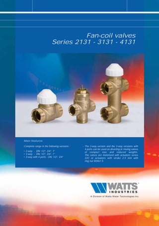
  • 1. Fan-coil valves Series 2131 - 3131 - 4131 Main features Complete range in the following versions : - The 3-way version and the 3-way versions with 4 ports can be used as diverting or mixing valves • 2-way - DN: 1/2”, 3/4”, 1” of compact size and reduced weights. • 3-way - DN: 1/2”, 3/4”, 1” The valves are motorized with actuators series • 3-way with 4 ports - DN: 1/2”, 3/4” 22C or actuators with stroke 2.5 mm with ring nut M30x1.5.
  • 2. FAN-COIL VALVES Description Fan-coil control valves series 2131, 3131, 4131 are used for controlling the flow of hot or cold water in heating and air conditioning systems. They are operated by electric actuators with max. stroke of 2.5 mm. such as 2 electrothermic actuator series 22C. As standard, the valves are available in the configuration with male thread in the following versions : • 2-way series 2131 • 3-way series 3131 • 3-way with 4 ports series 4131 with built-in by-pass. Operation of the valve plug is by electrothermic actuator series 22C, available in the following versions: • NO (normally open) 2-wire(Standard) or 4-wire (with auxiliary microswitch contact) • NC (normally closed) 2-wire (Standard) or 4-wire (with auxiliary microswitch contact) All actuators of the 22C series can easily be fastened to the valve body with a threaded ring nut. (M30x1.5). 2131 Two-way brass valve for fan-coils. ON/OFF operation with actuators series 22C. Max. operating temperature: 100°C. Disc stroke: 2.5 mm. Nominal pressure: 16 bar. Type Part number Dn Kvs Weight (g) 2131 213112 1/2" MM 1,7 200 2131 213134 3/4" MM 2,8 200 2131 21311 1" MM 4,5 500 3131 Three-way brass valve for fan-coils. ON/OFF operation with actuators series 22C. Max. operating temperature: 100°C. Disc stroke: 2.5 mm. Can be used both as mixing and diverting valve, except for version 31311 which can only be used as diverting valve. Nominal pressure: 16 bar. The Kvs and by-pass Kvs values given in the table alongside refer to the valve used for diverting service. Type Part number Dn Kvs Kvs By-bass Weight (g) 3131 313112 1/2" MM 1,7 1,3 200 3131 313134 3/4" MM 2,8 1,8 250 3131 31311 1" MM 4,5 3,1 550 VU Tee fitting for creating by-pass in valves series 3131 (Dn 1“). Type Part number Dn Weight (g) VU VU311 1" MM 250
  • 3. FAN-COIL VALVES 4131 Three-way brass valve with 4 connections for fan-coils. ON/OFF operation with actuators series 22C. Max. operating temperature: 100°C. Disc stroke: 2.5 mm. Can be used both as mixing and diverting valve. Nominal pressure: 16 bar. 3 The Kvs and by-pass Kvs values given in the table alongside refer to the valve used for diverting service. Type Part number Dn Kvs Kvs By-bass Weight (g) 4131 413112 1/2" MM 1,7 1,3 350 4131 413134 3/4" MM 2,8 1,8 400 840 Soft sealed union with nut for zone valves series 2131, 3131, 4131. Type Part number Dn Weight (g) 840 8401212GAS 1/2" x 1/2" 50 840 8403434GAS 3/4" x 3/4" 50 840 84011GAS 1" x 1" 50 Application The valves are used for shutting off (series 2131, two-way) or diverting/mixing (series 3131 - 4131, 3-way and 3-way with 4 ports size 1/2” e 3/4”), the heat transfer fluid to a heating or air conditioning system as required by the room thermostat (or timing thermostat). The 3-way fan-coil valves series 3131 or 3-way with 4 ports series 4131, thanks to the special configuration of the plug controlling the by-pass flow, can be used equally well as diverting or mixing valves (thus optimizing to the full the various plumbing requirements in assembly). Diverting AB A B Mixing B AB A
  • 4. FAN-COIL VALVES Operation Operation of the fan-coil control valves 2131,3131,4131 is through the movement of the plug which shuts off the heat transfer fluid: the ON/OFF action of the plug is controlled by the actuator series 22C whose internal motor 4 consists of a wax thermostatic element activated by a PTC thermistor against a signal sent by a room thermostat (or timing thermostat). The electrochemical actuator series 22C, in the 4-wire version, is provided with an auxiliary contact for additional controls (metering, control of pumps, fans or other equipment). The mechanical characteristic of the valves is of the Normally Open type. It can be adjusted or fully closed by manually turning the threaded plastic cap, provided on the valve. This threaded cap acts directly on the valve stem. When coupled to the 22C NC actuator, under rest conditions (actuator not energized), the valve becomes • normally closed (NC) (straight way closed and by-pass open if 3-way type); when the actuator is energized, the valve is opened. When coupled to the 22C NA actuator, under rest conditions (actuator not energized), the valve remains • normally open (NO) (straight way open and by-pass closed if 3-way type); when the actuator is energized, the valve is closed. The hydraulic flow rate and pressure drops characteristics of the valves are given in appropriate charts; instead, when coupled with the ON/OFF actuators, they assume the characteristics associated with such device. The three-way valves (or three-way valves with 4 ports) are designed and built to be used both as diverting valves (one inlet and two outlets) and mixing valves (two inlets and one outlet). It is recommended to observe the operating Pmax given in the table in order to avoid risk of malfunctions and/or noise. The reliability of the fan-coil control valves 2131, 3131, 4131 is guaranteed by the 100% testing on the production, which checks the hydraulic seals of the valve body and its components towards the outside and the seal of the plug in its flow shut-off function. Design features Body Brass CW617N Stem Brass with chemical nickel-plating Spring Stainless steel Plug rubber EPDM Technical features common to the entire range Max pressure, models w. constant Kv 16 bar Max pressure, models w. variable Kv 10 bar Min. fluid temperature 4°C Max. fluid temperature 110°C Liquids which can be used Water (with glycol 50%) Plug stroke 2.5 mm By-pass leakage 0,02 % Kvs Actuator connection Threaded ring nut M30 x 1.5 Installation Choice of the fan-coil control valves depends on the type of plumbing systems as well as the required flow rate and pressure drop characteristics. In systems with 2-way control valves it is advisable to provide by-pass valves series 466 to ensure a minimum recirculation of the fluid. Before mounting the valves, make sure that the piping is clean, and free from welding slag or the like. It is recommended not to install the valve with the 22C actuator facing down. The valves can be connected by using the soft-sealed tailpieces series 840 with the range of single-piece or union fittings (3-piece). The 1” three-way valves can use the TEE fitting (part No. VU311 - DN 1”) for making the by-pass.
  • 5. FAN-COIL VALVES Hydraulic characteristics Pre-setting (Kv adjustable) Max. operation pressure Close off with actuator Close off with actuator 5 operation pressure. operation pressure. Valve part number (noise < 38 dBA) (noise < 38 dBA) Max. differential Max. differential 22C NO/NC 22C NO/NC Kv by-pass Kv by-pass DN Inches Port size PN [bar] DN mm Pmax Pmax [bar] [bar] [bar] [bar] Kvs Kvs Ps Ps 2 WAY VALVES 213112 1/2" 15 15A2 16 1,7 - 0,8 2,5 - - - - 213112P 1/2" 15 15F2 16 1,7 - 0,8 2,5 - - - - 213112DP 1/2" 15 15A2 1,7 - 0,8 4 - - - - 213134 3/4" 20 20A2 16 2,8 - 0,7 1,5 - - - - 213134P 3/4" 20 20F2 16 2,6 - 0,7 1,5 - - - - 213134DP 3/4" 20 20A2 16 2,8 - 0,7 4 - - - - 21311 1" 25 25A2 16 4,5 - 0,6 0,7 - - - - 21311P 1" 25 25F2 16 4,5 - 0,6 0,7 - - - - 21311DP 1" 25 25A2 16 4,5 - 0,6 4 - - - - 3 WAY VALVES Used as DIVERTER VALVE Used as MIXING VALVE 313112 1/2" 15 15A3 16 1,7 1,3 0,8 2,5 1,7 1,2 0,7 2 313112P 1/2" 15 15F3 16 1,7 1,3 0,8 2,5 1,7 1,2 0,7 2 313112DP 1/2" 15 15A3 16 1,7 1,3 0,8 4 1,7 1,2 0,7 4 313134 3/4" 20 20A3 16 2,8 1,8 0,7 1,5 2,5 1,6 0,5 1 313134P 3/4" 20 20F3 16 2,8 1,8 0,7 1,5 2,5 1,6 0,5 1 313134DP 3/4" 20 20A3 16 2,8 1,8 0,7 4 2,5 1,6 0,5 1 31311 1" 25 25A3 16 4,5 3,1 0,6 0,7 4,5 3,1 0,4 0,7 31311P 1" 25 25F3 16 4,5 3,1 0,6 0,7 4,5 3,1 0,4 0,7 31311DP 1" 25 25A3 16 4,5 3,1 0,6 4 4,5 3,1 0,4 4 3 WAY VALVES 4 PORT Used as DIVERTER VALVE Used as MIXING VALVE 413112 1/2" 15 15A4 16 1,7 1,3 0,8 2,5 1,7 1,2 0,7 2 413112P 1/2" 15 15F4 16 1,7 1,3 0,8 2,5 1,7 1,2 0,7 2 41311240P 1/2" 15 15I4 16 1,7 1,3 0,8 2,5 1,7 1,2 0,7 2 413112DP 1/2" 15 15A4 16 1,7 1,3 0,8 4 1,7 1,2 0,7 4 413134 3/4" 20 20A4 16 2,8 1,8 0,7 1,5 2,5 1,6 0,5 1 413134P 3/4" 20 20F4 16 2,6 1,8 0,7 1,5 2,5 1,6 0,5 1 413134DP 3/4" 20 20A4 16 2,8 1,8 0,7 4 2,5 1,6 0,5 4 41313440P 3/4" 20 20I4 16 2,8 1,8 0,7 1,5 2,5 1,6 0,5 1 • Red part numbers are standard versions • KVs = nominal value of the flow in the main way of the valve in m3/h with the valve fully open at a pressure of 1 bar and with water temperature at 20 °C • Pmax = maximum dynamic differential pressure at the ends of the fully open valve, without risk of noise ( < 38 dBA) • Ps= maximum static differential pressure at the ends of the valve against which the valve is able to be opened (through its internal spring for the three-way versions; through the actuator for the two-way versions)
  • 6. FAN-COIL VALVES Overall dimensions (mm) 6 2131 3131 C C B D B D DN DN A A Part number DN A B C D Part number DN A B C D 213112 1/2” 52 29 13,5 51 313112 1/2” 52 29 13,5 68,5 213112P 1/2” 52 29 13,5 51 313112P 1/2” 52 29 13,5 68,5 213112DP 1/2” 52 29 13,5 51 313112DP 1/2” 52 29 13,5 68,5 213134 3/4” 56 28 13,5 56 313134 3/4” 56 28 13,5 69,5 213134P 3/4” 56 28 13,5 56 313134P 3/4” 56 28 13,5 69,5 213134DP 3/4” 56 28 13,5 56 313134DP 3/4” 56 28 13,5 69,5 21311 1” 82 30,5 13,5 77,5 31311 1” 82 38 13,5 92,5 21311P 1” 82 30,5 13,5 77,5 31311P 1” 82 38 13,5 92,5 21311DP 1” 82 30,5 13,5 77,5 31311DP 1” 82 38 13,5 92,5 4131 B C DN D E A Part number DN A B C D E 413112 1/2” 52 29 13,5 95,5 35 413112P 1/2” 52 29 13,5 95,5 35 413112DP 1/2” 52 29 13,5 95,5 35 41311240P 1/2” 52 29 13,5 100,5 40 41313440P 3/4” 56 28 13,5 102,5 40 413134 3/4” 56 28 13,5 112,5 50 413134P 3/4” 56 28 13,5 112,5 50 413134DP 3/4” 56 28 13,5 112,5 50
  • 7. FAN-COIL VALVES Connections dimensions (mm) 15F2 15A2 7 Ø14.5 +0.1 Ø13.8 +0.1 0 0 45° G1/2 G 1/2 1.5 12.7 10 17.2 10 20F2 20A2 ° 45 Ø20.5 G 3/4 G 3/4 Ø19.5 1.5 14.5 12.5 18 10 25A2 25F2 1.5 ° 45 Ø26 G1 Ø24 G1 21.5 12 21.5 12
  • 8. FAN-COIL VALVES 15A3 15F3 8 1.5 Ø14.5 +0.1 0 Ø13.8 +0.1 0 45° G 1/2 G 1/2 10 17.2 10 12.7 15.9 10 20A3 20F3 1.5 12.5 Ø20.5 G 3/4 Ø19.5 G 3/4 45° 14.5 18 14.1 9.5 10 25A3 25F3 1.5 ° Ø26 G1 Ø24 G1 45 12 21.5 12 21.5 12 12
  • 9. FAN-COIL VALVES 15A4 15F4 1.5 Ø14.5 +0.1 0 9 45° Ø13.8 +0.1 0 G 1/2 G 1/2 17.2 10 12.7 35 10 35 13.5 12.7 15I4 20A4 +0.1 0 1.5 Ø13.8 Ø20.5 45° G 3/4 G 1/2 17.2 10 14.5 50 10 40 15 15 20F4 20I4 Ø19.5 G 3/4 Ø19.5 G 3/4 12.5 18 40 50 12.5 18
  • 10. FAN-COIL VALVES Flow rate/pressure drop charts 8 2131 - 3131 - 4131 Straight way Diverting + Mixing Kv 1,7 DN 1/2" by-pass Diverting Kv 1,3 [ kPa ] by-pass Mixing Kv 1,2 [ m bar ] [ mm c.a. ] 20 200 2000 10 100 1000 8 80 800 5 50 500 4 40 400 PRESSURE DROP 3 30 300 2 20 200 1 10 100 0.8 0.5 5 50 0.3 3 30 0.2 2 20 0.1 1 10 10 20 30 50 100 200 300 500 1000 2000 3000 [ l/h ] [ m3/h ] 0.01 0.02 0.03 0.05 0.1 0.2 0.3 0.5 1 2 3 FLOW RATE 2131 - 3131 - 4131 Straight way Diverting Kv 2,8 DN 3/4" Straight way Mxing Kv 2,5 by-pass Diverting Kv 1,8 [ kPa ] by-pass Mixing Kv 1,6 [ m bar ] [ mm c.a. ] 20 200 2000 10 100 1000 8 80 800 5 50 500 4 40 400 PRESSURE DROP 3 30 300 2 20 200 1 10 100 0.8 0.5 5 50 0.3 3 30 0.2 2 20 0.1 1 10 10 20 30 50 100 200 300 500 1000 2000 3000 [ l/h ] [ m3/h ] 0.01 0.02 0.03 0.05 0.1 0.2 0.3 0.5 1 2 3 FLOW RATE
  • 11. FAN-COIL VALVES Flow rate/pressure drop charts 2131 - 3131 Straight Way Diverting - Mixing Kv 4,5 DN 1" 9 [ kPa ] by-pass Kv 3,1 [ m bar ] [ mm c.a. ] 20 200 2000 10 100 1000 8 80 800 5 50 500 4 40 400 PRESSURE DROP 3 30 300 2 20 200 1 10 100 0.8 0.5 5 50 0.3 3 30 0.2 2 20 0.1 1 10 10 20 30 50 100 200 300 500 1000 2000 3000 [ l/h ] [ m3/h ] 0.01 0.02 0.03 0.05 0.1 0.2 0.3 0.5 1 2 3 FLOW RATE The descriptions and photographs contained in this brochure are supplied by way of information only and are not binding. Watts Industries reserves the right to carry out any technical and aesthetic modifications to its products without prior notice.
  • 12. Product range Watts Industries - System disconnectors - Temperature control - Backflow protection devices - Expansion vessels - Check valves - Process switches - Safety units - Fuel products - Safety relief valves - Gas products - Pressure reducing valves - Electronic controls - Automatic control valves - Installation protection products - Butterfly valves - Radiator valves - Shut off valves - System products - Measuring gauges - Manifolds and fittings Re-order no. 69-0015-UK-IT/1-09-08-Rev.2 Watts Industries Italia S.r.l. Via Brenno, 21 - 20046 Biassono (MI), Italia Ph. +39 039 4986.1 - Fax +39 039 4986.222 e-mail : info@wattsindustries.it - www.wattsindustries.com