
Recommended
More Related Content
What's hot
What's hot (20)
Similar to Rte 1 en
Similar to Rte 1 en (20)
More from Oliverh Kalprit
More from Oliverh Kalprit (20)
Recently uploaded
Recently uploaded (20)
Rte 1 en
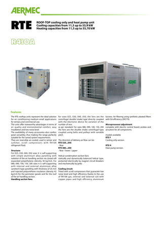
- 1. ROOF-TOP cooling only and heat pump unit Cooling capacities from 11,3 up to 55,9 kW Heating capacities from 11,5 up to 55,70 kWRTE The RTE rooftop units represent the ideal solution for air conditioning medium-small applications for tertiary and commercial use. The units offer noteworthy advantages in terms of air quality and environmental comfort, easy installation and low noise level. The availability of many accessories also confers great versatility, thus making the range perfectly suitable for the varied system requirements. They are reversible air-cooled, used in winter and summer, scroll compressors with R410A refrigerant fluid. Structure: For 025, 030, 040, 050 sizes it is self-supporting with simple aluminium alloy panelling with isolation of the air handling section via closed cell expanded polyethylene (density 30 kg/m3). For 080, 090, 100, 150, 200 sizes it is self-supporting with internal and external aluminium alloy sandwich-type panelling with thickness of 25 mm and injected polyurethane insulation (density 42 kg/m3) for the perimeter panels and for the roof of the air handling section. Handling section fans: for sizes 025, 030, 040, 050, the fans are the centrifugal double intake type directly coupled with the electronic device for variation of the number of revs as per standard. For sizes 080, 090, 100, 150, 200 the fans are the double intake centrifugal type coupled using belts and pulleys with variable pitch. The direction of delivery air flow can be: RTE 020...050 - Rear RTE 080...200 - Rear / lower / upper Helical condensation section fans: statically and dynamically balanced helical type, protected electrically by magnet circuit breakers and mechanically by grids. Cooling circuit: Fitted with scroll compressors that guarantee low noise level and high efficiency thanks to the use of R410A gas, internal and external coil with copper pipes and high efficiency aluminium louvers. Air filtering using synthetic pleated filters with G4 efficiency (EN779). Microprocessor adjustment complete with electric control board, probes and actuators for all components. models available RTE F Cooling only version. RTE H Heat pump version. Features
- 2. SM - Mixing chamber 2 dampers. Including damper servocontrols and rain-proof hoods. SM3P - Mixing chamber 3 dampers. 3-damper mixing chamber with return fan and rear intake, including damper servocontrols, rain-proof hoods and management of the free-cooling for tempe- rature. SM3I - Mixing chamber 3 dampers. 3-damper mixing chamber with return fan and lower intake, including damper servocontrols, rain-proof hoods and management of the free-cooling for tempe- rature. SCSM - Mixing chamber 2 dampers. Including servocontrols with dampers spring return and rain-proof hoods. SCSM3P - Mixing chamber 3 dampers. 3-damper mixing chamber with return fan and rear intake, including spring return servocontrols, dampers, rain-proof hoods and management of the free-cooling for temperature. SCSM3I - Mixing chamber 3 dampers. 3-damper mixing chamber with return fan and lower intake, including spring return servocontrols, dampers, rain-proof hoods and management of the free-cooling for temperature. P - filters pressure switch. BRT2 - 2 row water coils . Water coils for two row heating. BRT3 - 3 row water coils Water coil for three row post-heating. BRE - Electric coils. Electric coil. See the table below. TP - Pressure transducers. As per standard on all heat pump models. DCPR - PRESSURE CONTROL device. Extends the functioning range of the rooftop in the summer cycle (minimum temperature of the external air up to 10 °C) and in the winter cycle in heat pump mode (maximum temperature of the external air up to 25 °C). Moreover, it makes functioning silent with par- tial loads. A regulation circuit board varies the number of the motor condensing fan revs on the basis of the condensation pressure, read by the relevant transdu- cers, thus guaranteeing correct power supply of the thermostatic valve. DP - dehumidification and post-heating kit. Kit for management of dehumidification and post-hea- ting. It can be coupled with the PUC accessory (Humidification contact). FCH - enthalpy freecooling. Only for models from 100 to 200 and the 3-damper mixing chamber, if present. It can be coupled with: - the DP accessory (dehumidification and post-heating management kit) only in presence of the 3-shutter mixing chamber and water or electric coil. - the PUC accessory (Humidification contact) only with 3-damper mixing chamber. puc - humidification contact Only for 100, 150, 200 models. ON/OFF contact (normally open) for humidification consent. In this case, the unit is complete with one humidity probe positioned in the environment air return. A humidity probe is also supplied to be positio- ned downstream from the humidification section. sqa Air quality probe. Only for 100, 200 models. PR2 - REMOTE panel. Allows to control the rooftop at a distance. GP - protection grid. Protects the external coil from blows and to prevents access to the underlying area where the compressors and the chiller circuit are housed. VT - Rubber anti-vibration mounts. Rubber anti-vibration mounts. Select the VT model from the compatibility table. AVX - Spring anti-vibration mounts. Spring anti-vibration mounts. Select the AVX model from the compatibility table. RC Roof-curb. Only for models from 080 to 200. Attention: The standard configuration control is howe- ver able to manage the following accessories, which can also be added at a later date, SM, PF, SSV (supervi- sor), PR2, TP. For any other accessory, change the elec- tric control board. Independently from the type of control, GP , VT, AVX, RC can be supplied at a later date. Accessories (1) Only if 3-damper mixing chamber and water or electric coil present. (2) Only with 3-damper mixing chamber. (3) Only if electric or water coil present. (4) BRE103 = electric coils, the first indicates the stages, the last two characters indicate the power (e.g.: 1 stage, 3 kW). Mod. 25 30 40 50 80 90 100 150 200 SM • • • • • • • • • SM3P • • • • • • • • • SM3I • • • • • SCSM • • • • • • • • • SCSM3P • • • • • • • • • SCSM3I • • • • • PF • • • • • • • • • BRT2 • • • • • • • • • BRT3 • • • • • • • • • BRE103 (4) • • • • BRE106 • • • • BRE109 • • • • BRE107 • • BRE112 • • BRE118 • • BRE212 • • • BRE218 • • • BRE224 • • • BRE236 • • • TP • • • • • • • • • DCPR • • • • • • • • • DP • • • • • • • • • DP+FCH (1) • • • PUC+FCH (2) • • • PUC+DP (3) • • • FCH • • • PUC • • • SQA • • • PR2 • • • • • • • • • GP • • • • • • • • • VT • • • • • • • • • AVX • • • • • • • • • RC • • • • •
- 3. Technical data RTE F 25 30 40 50 80 90 100 150 200 Cooling capacity kW 11,3 13,2 17,2 20,9 25,5 29,7 39,7 48,8 55,9 Sensitive nominal cooling capacity kW 6,8 8,2 10,3 12,4 15,7 18,8 24 29,6 32,8 Compressor input power kW 2,4 2,9 3,2 3,8 5,4 6,2 8,1 10,7 11,8 EER W/W 4,71 4,55 5,38 5,50 4,72 4,79 4,90 4,56 4,74 RTE H 25 30 40 50 80 90 100 150 200 Cooling capacity kW 11,1 13,2 16,7 20,3 25,1 29,5 39,4 48,3 55,5 Sensitive nominal cooling capacity kW 6,7 8,2 10,2 12,2 15,5 18,7 23,8 29,4 32,5 Compressor input power kW 2,4 3 3,3 4 5,4 6,2 8,1 10,7 11,80 EER W/W 4,63 4,40 5,06 5,08 4,65 4,76 4,86 4,51 4,70 Heating capacity kW 11,5 12,5 17,1 19,3 25,3 29,1 39,1 48,6 55,70 Compressor input power kW 2,3 2,3 3,1 3,3 4,6 5,6 6,9 8,8 10,40 COP W/W 5,00 5,43 5,52 5,85 5,50 5,20 5,67 5,52 5,36 Nominal air flow rate internal fans m3/h 1.500 1.900 2.400 2.900 4.000 4.500 6.000 8.000 9.000 Minimum air flow for the handling section m3/h 1.275 1.615 2.040 2.465 3.400 3.825 5.100 6.800 7.650 Maximum air flow for the handling section m3/h 1.725 2.185 2.760 3.400 4.600 5.175 6.900 9.200 10.350 Compressors type Scroll n° 1 1 1 1 1 1 1 1 1 Cooling circuits n° 1 1 1 1 1 1 1 1 1 Fans type Axial External fans n° 1 1 1 1 1 1 4 4 4 Internal fans n° 1 1 1 1 2 2 2 2 2 Air filters type G4 Thickness mm 50 Evaporator type 1 Maximum available pressure Pa 315 275 345 287 350 330 365 360 330 Water coil heating capacity * kW 16,3 19,2 22,5 25,5 36,1 39 57 68,9 74,4 22,5 27 32,2 37,1 52,1 56,8 81,8 100,4 109,3 Electric coil heating capacity kW 3/6/9 3/6/9 3/6/9 6/12/18 6/12/18 12/18/24/36 12/18/24/36 12/18/24/36 12/18/24/36 Sound pressure level dB(A) 58 58 61 61 64 64 67 67 67 Electrical power supply V/Ph/Hz 400/3+N/50 Cooling capacity RH 50% (Twb 19°C), Text 35°C RH 50%; Operation with 30% of ambient air and expelled (version with mixing chamber with three dampers SM3). Nominal air flow. Heating capacity Heating capacity Tin 20°C RH 50%, Text 7°C RH 70%. Operation with 30% of ambient air and expelled (version with mixing chamber with three dampers SM3). Nominal air flow. Sound pressure: Sound pressure in free field, at 10 m distance from the external surface of the unit (in accor- dance with UNI EN ISO 3744) * Room air 20°C d.b., water 80/70°C.
- 4. Aermec S.p.A. Via Roma, 996 - 37040 Bevilacqua (VR) - Italy Tel. 0442633111 - Telefax 044293577 www.aermec.com Aermec reserves the right to make all modification deemed necessary for improving the product at any time with any modification of technical data. Code:SRTE025_200UY.02/1301 Dimensional data (mm) Dimensions and weights of the basic set-up unit. C A B A B C A B C 025 - 030 040 - 050 080 - 200 RTE 25 30 40 50 80 90 100 150 200 Height A mm 1.040 1.040 1.040 1.040 1.175 1.175 1.500 1.500 1.500 Width B mm 1.175 1.175 1.175 1.175 1.240 1.240 1.510 1.510 1.510 Depth C mm 1.155 1.155 1.155 1.155 1.805 1.805 2.710 2.710 2.710 RTE F weight kg 235 250 270 285 435 450 650 675 735 RTE H weight kg 245 260 280 300 455 470 690 710 770