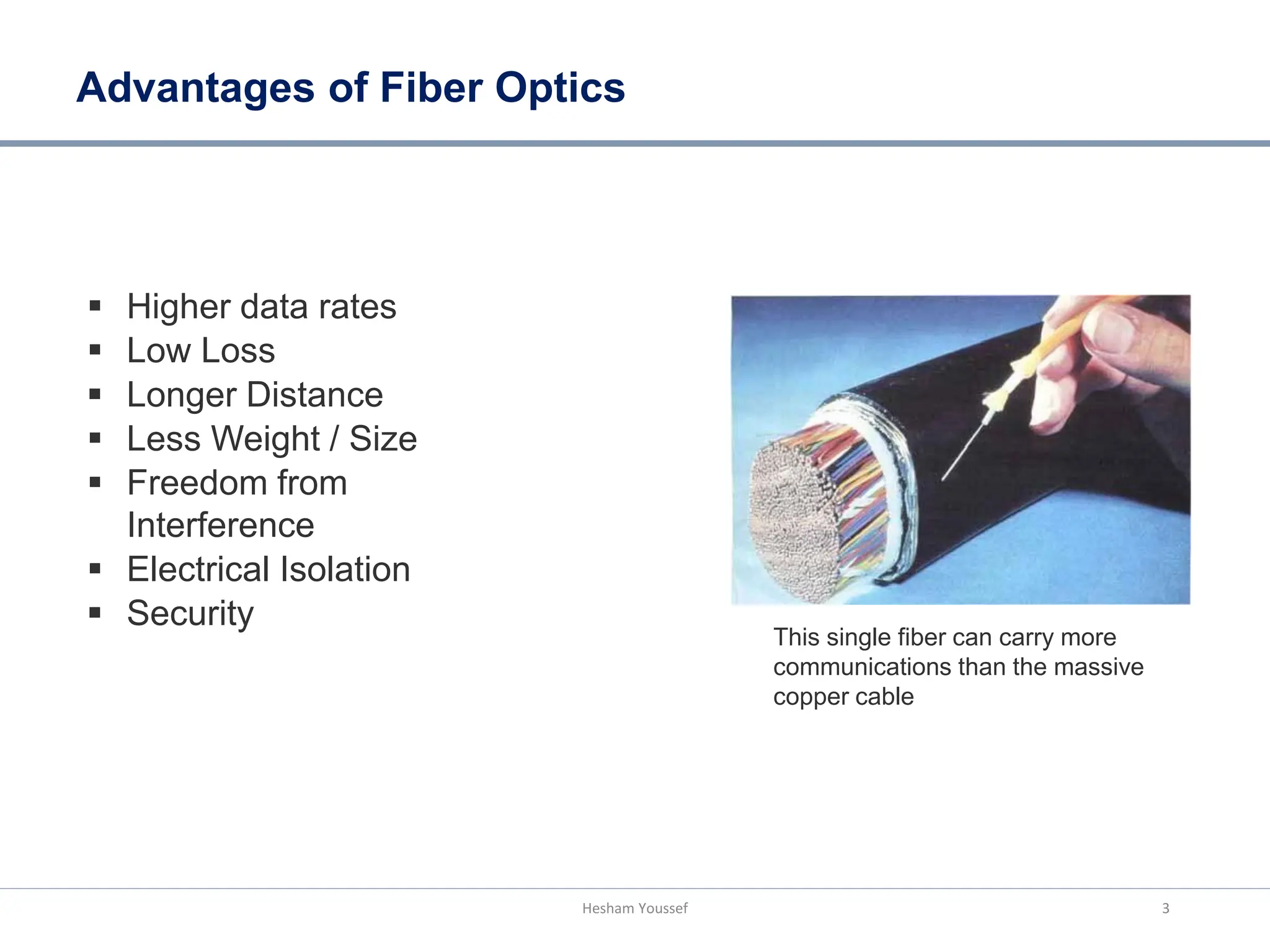
By: Hesham Youssef
Optical Fiber Transmission
What is Fiber Optics?
Cladding
Core
Buffer
Fiber Structure
Transmission of communication
signals in the form of light over thin
glass or plastic (Fiber).
Pulses of infrared light guided through
glass fibers move huge blocks of data
over long or short distances
n1
n2
Propagation of Light
inside the Fiber
2
Hesham Youssef
Advantages of Fiber Optics
 Higher data rates
 Low Loss
 Longer Distance
 Less Weight / Size
 Freedom from
Interference
 Electrical Isolation
 Security
This single fiber can carry more
communications than the massive
copper cable
3
Hesham Youssef
Bandwidth Demand
4
250
Data
200
Data Traffic overtakes Voice Traffic
100
150
Voice
Voice Traffic  13 %
Data Traffic  300 %
1996 1999
50
And at the same time number of
users also increasing
1990 1993
Voice-centric
2002 2005
Data-centric
* Source: Cisco Systems White Paper
Hesham Youssef
Options for Increasing the Bandwidth
More Fibers Installing new fibers (Fiber Bundle)
Same bit rate, more fibers
Estimated cost is about $70,000 per mile
Increasing the bit rate
Higher bit rate, same fiber
Expensive and Complex Electronics
WDM
Increasing the number of wavelengths
Same fiber, bit rate, more wavelengths
• By using TDM and WDM, the effective capacity of the existing fiber
will increase.
Faster Electronics
(TDM)
5
Hesham Youssef
Wavelength Division Multiplexing (WDM)
6
• Multiplexing several optical signals having different wavelengths and transmitting
simultaneously over a single fiber is known as wavelength division multiplexing.
• WDM increases the carrying capacity of the physical Fiber using a completely
different method from TDM
Hesham Youssef
TDM
MUX
2.5 Gb/s
Fiber 10 Gb/s (λ1)
TDM
MUX
2.5 Gb/s
Fiber 10 Gb/s (λ3)
TDM
MUX
2.5 Gb/s
Fiber 10 Gb/s (λ2)
WDM
MUX
Fiber 30 Gb/s
Fiber Attenuation Vs Wavelength
O = Original
E = Extended
S = Short
C = Conventional
L = Long
U = Ultra-long
1530-1565
C-band
1565-1625
L-band
1460-1530
S-band
1360-1460
E-band
1260-1360
O-band
10
1625-1675
U-band
1.0
Attenuation
(dB/km)
Standard fiber
0.1
1000 1100 Wavelength (nm)
1200 1300 1400 1500 1600 1700
Attenuation (Loss) per kilometer (dB/km)
0.40 dB/km at 1310 nm
0.25 dB/km at 1550 nm
*Source: commtel networks
Hesham Youssef 7
Evolution of transmission capacity
8
[P. Winzer et al., IEEE JLT, Dec. 2012]
Hesham Youssef

PLC3.pdf

  • 1.
    By: Hesham Youssef OpticalFiber Transmission
  • 2.
    What is FiberOptics? Cladding Core Buffer Fiber Structure Transmission of communication signals in the form of light over thin glass or plastic (Fiber). Pulses of infrared light guided through glass fibers move huge blocks of data over long or short distances n1 n2 Propagation of Light inside the Fiber 2 Hesham Youssef
  • 3.
    Advantages of FiberOptics  Higher data rates  Low Loss  Longer Distance  Less Weight / Size  Freedom from Interference  Electrical Isolation  Security This single fiber can carry more communications than the massive copper cable 3 Hesham Youssef
  • 4.
    Bandwidth Demand 4 250 Data 200 Data Trafficovertakes Voice Traffic 100 150 Voice Voice Traffic  13 % Data Traffic  300 % 1996 1999 50 And at the same time number of users also increasing 1990 1993 Voice-centric 2002 2005 Data-centric * Source: Cisco Systems White Paper Hesham Youssef
  • 5.
    Options for Increasingthe Bandwidth More Fibers Installing new fibers (Fiber Bundle) Same bit rate, more fibers Estimated cost is about $70,000 per mile Increasing the bit rate Higher bit rate, same fiber Expensive and Complex Electronics WDM Increasing the number of wavelengths Same fiber, bit rate, more wavelengths • By using TDM and WDM, the effective capacity of the existing fiber will increase. Faster Electronics (TDM) 5 Hesham Youssef
  • 6.
    Wavelength Division Multiplexing(WDM) 6 • Multiplexing several optical signals having different wavelengths and transmitting simultaneously over a single fiber is known as wavelength division multiplexing. • WDM increases the carrying capacity of the physical Fiber using a completely different method from TDM Hesham Youssef TDM MUX 2.5 Gb/s Fiber 10 Gb/s (λ1) TDM MUX 2.5 Gb/s Fiber 10 Gb/s (λ3) TDM MUX 2.5 Gb/s Fiber 10 Gb/s (λ2) WDM MUX Fiber 30 Gb/s
  • 7.
    Fiber Attenuation VsWavelength O = Original E = Extended S = Short C = Conventional L = Long U = Ultra-long 1530-1565 C-band 1565-1625 L-band 1460-1530 S-band 1360-1460 E-band 1260-1360 O-band 10 1625-1675 U-band 1.0 Attenuation (dB/km) Standard fiber 0.1 1000 1100 Wavelength (nm) 1200 1300 1400 1500 1600 1700 Attenuation (Loss) per kilometer (dB/km) 0.40 dB/km at 1310 nm 0.25 dB/km at 1550 nm *Source: commtel networks Hesham Youssef 7
  • 8.
    Evolution of transmissioncapacity 8 [P. Winzer et al., IEEE JLT, Dec. 2012] Hesham Youssef