Download to read offline


![12
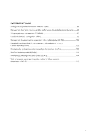
work. When the animations have been defined
for each assembly phase, the whole assem-
bly process can be simulated. The user can
see any animated assembly work phase or the
whole animated assembly work.
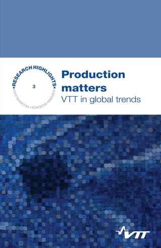
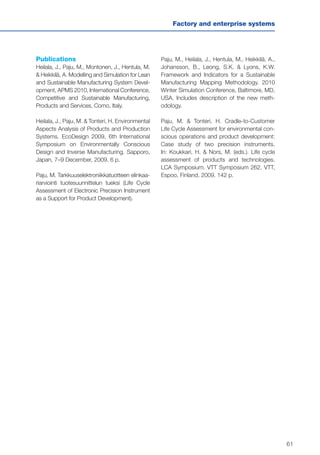
In the ‘Visualization’ phase, the user can
see animations that demonstrate the assem-
bly work of a device (Figure 2). The 3D model
of each assembly part is in a separate file and
the assembly order, animation definitions,
assembly instructions and references to the
part files are contained in another file.
In this project, a standard USB webcam
and markers are used for tracking 3D models
in the real environment.
Results
In this project, we have developed a method-
ology for applying 3D product data created
in commercial CAD systems to AR applica-
tions and then to the AR instructions [1]. The
data pipeline exploits the STEP data protocol
available in practically all CAD systems. The
data pipeline is tested in a real industry case,
in the assembly of the power unit of a tractor
accessory at the Finnish tractor factory Valtra
Plc. The project also examined how modern
smartphones could be used in augmented
reality devices. Currently, the biggest lack of
use of AR technology is on the hardware side.
Head-mounted displays felt uncomfortable
(weight, screen alignment of the eye, wires).
Students carried out the assembly work
of the hydraulic block in spring 2008 at Tam-
pere University of Technology. Eighty-nine per-
sons (74 men and 15 women) participated in
this experiment over three weeks. The assem-
bly work of the hydraulic block was carried out
using the paper instructions (assembly draw-
ing, parts list, assembly instructions) and the
AR-based instructions. In the test, the paper
instructions were compared with the assem-
bly AR instructions, including the assembly time
and the number of errors. The results were sig-
nificant. The assembly work was accelerated by
15% and the number of errors reduced by 84%.
Users generally admired that the AR tech-
nology was visual and easy to understand.
The AR technology was considered excellent.
Tough things were simple and clear with the
help of the AR animations. In fact, the work
seemed straightforward and fun. In sum-
mary, it could be said that the AR technology
enhanced work, showing a part/component of
the assembly in the right place. Unproductive
contemplation will end. Showing the correct
order of the work phase will also accelerate
the work.
Discussion and conclusions
Future research should explore whether the
described augmentation process for assem-
bly instructions improves assembly planning
and whether the process might reveal errors in
the assembly process earlier than in the prod-
uct design process when design changes are
easier and less expensive to make.
Exploitation potential
AR technology is a new interactive way of man-
machine interaction. Digital information can be
displayed to the user, combined with the right
environment. The information may be text data,
images, 3D models or any other visualized
material. With AR technology, the information
can be direct in a real environment and just to
the right point, for example, the information of
the part shown on the part etc. AR systems will
reduce assembly times, accelerate learning of
the assembly tasks and provide more quality
assurance on the factory floor.
Augmented reality may be used in many
other fields, such as education, training, weld-
ing, service, packaging and maintenance. For
example, the employee typically does certain
maintenance work only once. The AR-based
guidance would then really help him/her. Simi-
larly, the AR instructions in the training are very
visual and effective.](https://image.slidesharecdn.com/vttresearchhighlights3fgfissuuversio-140319040805-phpapp02/85/Production-matters-VTT-in-global-trends-12-320.jpg)
![13
Manufacturing methods
Acknowledgements
This contract-based research project is
funded by Tekes, the Finnish Agency for Tech-
nology and Innovation. VTT and key industrial
companies also partially covered the costs of
this work. The research team is grateful for the
contributions.
Publications
Pyykkö, T. Lisätyn todellisuuden hyö-
dyntäminen kokoonpanossa, Master’s thesis.
Tampere University of Technology, Tampere,
Finland, 2008. (In Finnish.)
Salonen, T., Sääski, J., Woodward, C.,
Hakkarainen, M., Korkalo, O. & Rainio, K. Aug-
mented assembly – Ohjaava kokoonpano. VTT
Working Papers 138. VTT, Espoo, Finland,
2008. 32 p. + app. 36 p. (In Finnish.)
Sääski, J., Salonen, T., Liinasuo, M. Kuu-
tion kokoaminen AR-teknologian avulla. VTT
Working Papers 89. VTT, Espoo, Finland,
2008. 27 p. + app. 1 p. (In Finnish.)
References
[1] Salonen, T., Sääski, J., Woodward, C.,
Korkalo, O., Marstio, I. & Rainio, K. Data
Pipeline from Cad to AR Based Assem-
bly Instructions. Proceedings of the 2009
World Conference of Innovative Virtual
Reality, WINVR09. 25–26 February, 2009,
Chaton-sur-Chaone, France.](https://image.slidesharecdn.com/vttresearchhighlights3fgfissuuversio-140319040805-phpapp02/85/Production-matters-VTT-in-global-trends-13-320.jpg)
![14
Transferable and reconfigurable production
systems (LIIKU)
Timo Salmi
Introduction
Today, production faces increasing require-
ments for flexibility and productivity: product
life cycles are shortening, variety is increasing
and production volumes are fluctuating, while
production costs should be reduced. The com-
petition puts pressure on automation, while, at
the same time, the flexibility needs make auto-
mation more difficult. Transferable or mobile
production machines have been suggested as
a potential solution to flexible and cost-effective
production with the following advantages:
• Enabling reconfiguring of production
systems, lines and workshops, and fast
ramp-ups of new lines.
• Automation can be used according to the
current needs.
• In the case of a varying production load,
the capacity can be transferred where it
is needed.
• The investment risks are reduced when
the capacity is easily transferred and used
somewhere else.
• When processing big products, the nec-
essary large movements are achieved by
mobile devices and the production devices
are transferred instead of the product.
• Transferable production systems offer
possibilities to make the product on site
or near the customer through tailoring
with industrial methods.
The aim of our research was to develop meth-
ods and tools that enable fast building and
transfer of production capacity according to the
changing production situations and to develop
concept solutions for different application areas.
Our approach was to find practical, cost-
efficient solutions to industrial environments
and situations in which production volumes
vary and the number of diverse products and
variants is high. Our aim was to cover different
types of flexibilities, from pure volume increase
to one-of-a-kind type production [1].
Methods
This project has a mostly constructive research
approach, a concept development with analytic
reasoning. The project started with an analy-
sis of different application areas in order to find
the solutions with most potential for transfer-
able robotic systems and their restrictions and
to define the requirements. The second phase
was a survey of potential enabling technolo-
gies and the selection of the building blocks for
the concept. The main focus has been on the
development of the different technological solu-
tions for the concept of the transferable robotic
system. A practical touch of real industrial needs
was obtained in case studies.
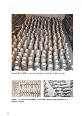
Results
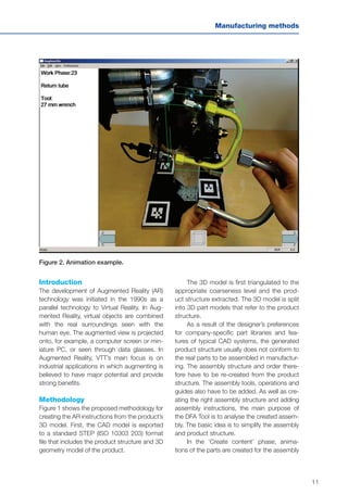
Our research found the solutions with most
potential for the transferable robotic systems
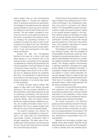
to be:
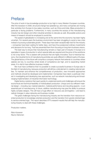
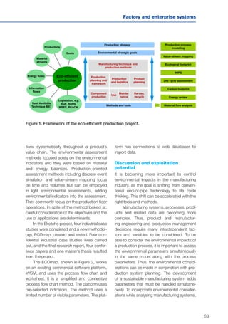
• easily transferable ready-to-use produc-
tion cells
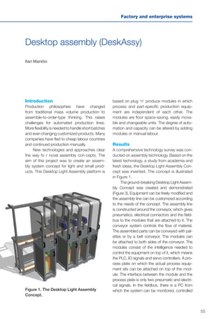
• a transferable universal robotic mod-
ule/platform for the material handling of
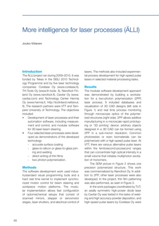
machine tools; see Figure 1](https://image.slidesharecdn.com/vttresearchhighlights3fgfissuuversio-140319040805-phpapp02/85/Production-matters-VTT-in-global-trends-14-320.jpg)
![15
Manufacturing methods
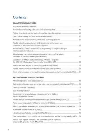
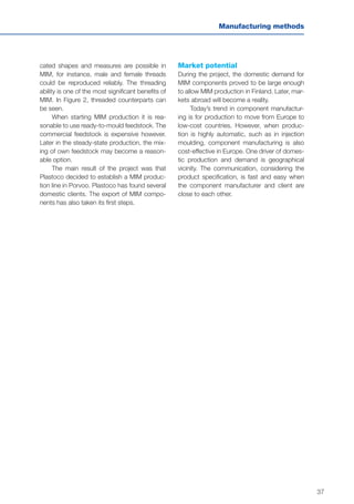
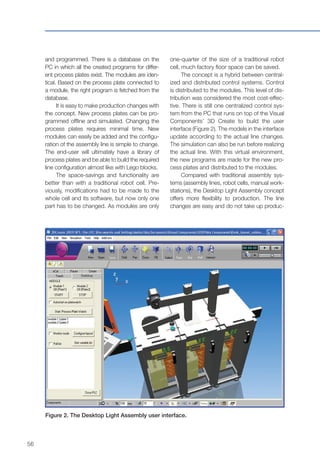
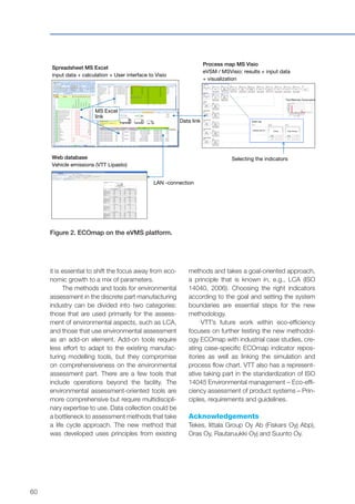
• welding or other processing tasks of big
products with a transferable robot sys-
tem; see Figure 2.
It seems that the requirements of the main
application areas are quite congruent while the
focus varies from case to case:
• well-functioning, fast calibration routines,
adaptability to inac-curacies
• ability to produce different products – ver-
satility
• non-part-specific mechanics – especially
in material handling
• the ability to adapt new products
• easy programming of new products –
especially in process applications
• transferability and compact design
• easily made interconnections, integration
to other systems
• easily transferable safety arrangements
• reconfigurability.
According to our technology survey, the
required functions can be achieved using a
variety of advanced technologies:
• a robot is a basic system component
• calibration methods and different sensor
technologies are essential components:
2D and 3D machine vision, seam-tracking
and other types of intelligent sensors
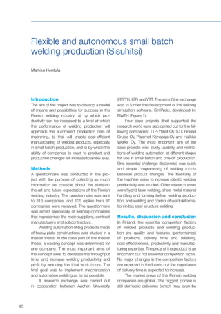
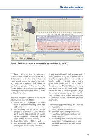
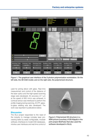
Figure 1. A conceptual picture of a trans-
ferable universal robotic platform for the
material handling of machine tools.
Figure 2. A conceptual picture of a freely
transformable robot platform used in a
welding application.
• versatile technologies for material han-
dling, e.g. servo grippers for a large
variety of parts and sensor-based mate-
rial handling methods
• advanced programming methods to
achieve easier new product implemen-
tation, at least partly automated off-line
programming, e.g. CAD or module-based
or parametric programming or sensor-
based program creation, task-oriented
programming or guiding
• a compact, integrated, easy-to-transfer
platform using a modular structure in the
mechanics, control system hardware and
software could achieve reconfigurability
• instead, the self-navigation or self-move-
ment functions are not the preliminary needs
• new types of safety sensors, laser scan-
ners or vision-based safety systems are
able to be integrated into the transferable
platform, and with the new safety robot
controllers it is possible to build space-
saving, fenceless, intelligent and dynamic
safety areas.
Many of the building blocks have similarities with
those of modular ultra-flexible production units
presented as Automation Islands [2]. The devel-
opment work focused on several areas, e.g. the
safety design met complicated challenges.](https://image.slidesharecdn.com/vttresearchhighlights3fgfissuuversio-140319040805-phpapp02/85/Production-matters-VTT-in-global-trends-15-320.jpg)
![16
As a result, the project introduced two con-
ceptual solutions with several stages according
to the needs of the applications.
Discussion, conclusions and
exploitation potential
Transferable robotic systems offer new pos-
sibilities to minimize investment risks and to
find a new type of cost-effective solution to
change the production environment. There
are also several challenges to be solved, but
application areas were found where this type
of solutions has special potential. As a result,
some concept solutions have been presented.
The development work also has meaning in a
wider perspective: most results are relevant
in production systems in which flexibility,
changeability and reactability are favourable.
The concept has combined the approaches of
Reconfigurable Manufacturing Systems (RMS)
and Flexible Manufacturing systems (FMS) [3].
The work is still in progress and the final
results will be published during 2012.
Acknowledgements
This project was part of the National Research
Programme SISU 2010 – Innovative Manu-
facture. The project was funded by Tekes, the
Finnish Funding Agency for Technology and
Innovation, VTT Technical Research Centre of
Finland and several industrial partners.
References
[1] Salmi, T., Heikkilä, T., Leino, K. & Väätäinen,
O. Transferable and reconfigurable robot-
based production units. Proceedings of the
3rd International Conference on Changeable,
Agile, Reconfigurable and Virtual Production,
CARV 2009, Munich, Germany. 10 p.
[2] Salmi, T., Haataja, K., Sallinen, M., Göös, J. &
Voho, P. Automation Islands – Requirements
and solutions for a highly flexible concept
of robotic systems. The 2nd International
Conference on Changeable, Agile, Reconfig-
urable and Virtual Production, CARV 2007,
Toronto, Canada. 10 p.
[3] ElMaraghy, H.A. Flexible and reconfigurable
manufacturing systems paradigms. Inter-
national Journal of Flexible Manufacturing
Systems, Special Issue on Reconfigurable
Manufacturing Systems 17, October 2005,
pp. 261–276.](https://image.slidesharecdn.com/vttresearchhighlights3fgfissuuversio-140319040805-phpapp02/85/Production-matters-VTT-in-global-trends-16-320.jpg)
![18
their own algorithms, which work nicely on cer-
tain workpieces. 3ideo’s Pick3D provides tools
for bin picking. The 3D data are fed into the
Pick3D and it returns the place and orienta-
tion of the part to be picked. MVTec’s Halcon
is a machine vision library with many 3D algo-
rithms. Two of the most interesting algorithms,
which can be used in bin picking, are shape-
based matching and surface-based matching.
Shape-based matching will read the CAD model
of the picked part and try to find such parts in
the analysed image (Figure 2). Shape-based
matching needs optimal lighting conditions and
takes quite a long time. Accuracy-wise it is best
if the camera is mounted on the robot to obtain
images from as close a range as possible even
though the cycle time will be reduced drastically.
Surface-based matching is a robust algorithm to
localize parts from a point cloud. It works in a
similar manner to Pick3D. The cycle time is good
but it needs good 3D data. Most of the time is
taken by the actual scanning process.
In most cases, the most cost-effective
way is to use standard grippers. Great atten-
tion should be paid to good gripper design.
The accuracy is often no better than a couple
of millimetres and the gripper should be able
to cope with that. Different gripping positions in
the workpiece should also be considered. If a
vacuum gripper is an option, it should be used.
It can pick from the top and will avoid collisions
with siding parts. If there are different parts, the
picked gripper should be designed accordingly.
Conclusions
As a rule of thumb: do not use bin picking if
you do not have to. It is still quite laborious
to realize bin picking and thus expensive. One
step towards flexibility by dedicated feeders is
the flexible feeder with which parts are fed to
a lit surface and localized with machine vision.
Bin picking is a functional technology, but
there are still some limitations part-wise and
cycle-time-wise. In some cases, it can signifi-
cantly reduce the need for manual labour.
Future research will continue in this area.
Some research institutes are researching the
possibilities of using cheap sensors like Micro-
Figure 1. Tests in Binar, Sweden.
Figure 2. Halcon shape-based matching.
soft Kinect for bin picking. More and more indus-
trial applications are popping up and speeding
up the development in providing companies.
More information can be found in the final
report of the project [1].
Publications
Final report of the project: Sekaisin olevien
kappaleiden käsittely konenäön avustamana
– Bin-Picking. (Picking of randomly oriented
parts with machine vision – BinPicking.) Avail-
able on request. (In Finnish.)
References
[1] Sekaisin olevien kappaleiden käsittely
konenäön avustamana – Bin-Picking.
(Picking of randomly oriented parts with
machine vision – BinPicking.) Available on
request. (In Finnish.)](https://image.slidesharecdn.com/vttresearchhighlights3fgfissuuversio-140319040805-phpapp02/85/Production-matters-VTT-in-global-trends-18-320.jpg)
![19
Manufacturing methods
Direct colour marking of metals with fibre
lasers (DIME)
Petri Laakso
Introduction
In most applications, laser marking is the fast-
est and cheapest method. The flexibility of
laser marking is based on writing with a laser
beam without the need for chemicals or tools.
Laser marking has had its limitations produc-
ing graphics and colours. Colour marking on
stainless steel and titanium has been avail-
able for some time but has not yet been used
widely in consumer products. There have
been some industrial applications however.
New fibre lasers allow independent tuning
of the pulse width, and the marking process
can be optimized to produce colours with
better quality and visual appearance. In this
study, the visual appearance of laser-marked
surfaces was optimized by varying the pulse
width, laser power, pulse energy and scanning
velocity. The aim was to create uniform oxide
layers on the surface that would appear as
high-quality colour markings.
Methods
In the beginning, the laser equipment used
in the project was the IPG 20W pulsed fibre
laser. A more tunable SPI-pulsed fibre laser
was used in most of the tests. As a reference,
a 20W Nd:YVO4
laser was tested to see the
difference between traditional and fibre lasers.
The surface characterization included surface
roughness, oxide thickness measurements
and an elementary analysis.
The materials tested were AISI grade
304L. The surface quality was 2B and the thick-
nesses 1 and 2 mm. Another selected material
was titanium of commercial purity 1 grade. The
thickness was 0.5 mm. The actual grade was
ASTM B265-99 G1/ASTM F67-00 G1.
Three different instruments were used to
measure the colours of the laser-marked sam-
ples. First, the spectrophotometer was used
to measure the total reflectance of the sam-
ples. Second, the fibre spectrometer was
used to measure the reflectance in multian-
gle measurements. Third, the spectral camera
was used to measure spectral images through
a microscope.
Results
Laser colour marking of metals has been used
for more than ten years with a variety of differ-
ent laser sources [1, 2, 3, 4].
The typical laser of choice for marking is
a q-switched crystal laser, which produces
pulses in the nanosecond regime. These
lasers do not allow independent adjustment
of the processing parameters, but the pulse
width is dependent on the repetition frequency
and as the frequency changes so does the
pulse width. Lasers that allow adjustment of
the pulse width regardless of the frequency
may therefore give an advantage in marking.
Some metals can be marked so that the
surface appears coloured. This is based on
oxidation and the following thin film effect. In
order to create a uniform and high quality mark,
the laser used must have good enough beam
quality and stability. A high quality mark results
in a smooth and uniform oxide layer. Oxide
formation during the laser process involves,
among other things, transport of oxygen from
the medium to the solid surface, adsorption of](https://image.slidesharecdn.com/vttresearchhighlights3fgfissuuversio-140319040805-phpapp02/85/Production-matters-VTT-in-global-trends-19-320.jpg)
![20
molecular oxygen and electric field-enhanced
diffusion of species through the oxide layer [5].
The laser-induced temperature rise enhances
the diffusion flux and the reaction rate within
the scanned area.
From the look of the laser-marked sam-
ples (Figure 1), it is not possible to say whether
they are good or bad in terms of corrosion.
The smooth oxide surface may look good, but
in the wear test, the oxide may be seriously
damaged. Roughness measurements do not
reveal any explanation of which surface may
be good or bad. It is therefore not easy to pre-
dict which colour or parameter setup will lead
to a good combination of all the properties.
When some colour is wanted on the sur-
face, the laser parameter may have to be set to
a particular parameter range and there may not
be any alternative parameters for doing this if
speed has to be maximized. If a slightly slower
marking speed is used, it is easier to tune the
parameters and different marking strategies to
also keep wear and corrosion in mind.
During the project, a wide variety of differ-
ent lasers were used. Commercially available
lasers kept improving during the project.
Conclusions
In this project, laser colour marking was further
developed and the marked areas were exam-
ined for wear, corrosion and colour. Before this
project, colour marking was available but the
colours could only be produced in a limited
way with one laser system, and another laser
might have been needed for other colours.
Good beam properties and tunability of the
laser make high quality marking with afford-
able equipment possible.
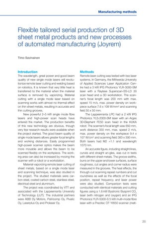
During the project, a wide variety of col-
ours was found. Almost all colours can be
marked on a stainless steel surface, though
Figure 1. Sample with different colours
marked on it.
the different shades of a colour may be chal-
lenging. From the corrosion results, we can
see that the marking speed has a big effect
on corrosion resistance, even if the heat input
remains the same. The wear tests clearly
showed that the laser colour marking param-
eters have a significant influence on the wear
behaviour of both the colour-marked stainless
steel surface and the counterpart surface.
The colours of the surfaces can be
explained by the thin film interference. The
thickness of the film together with the illumi-
nation angle determines the visible colour.
According to the results of the modelling, it
can be concluded that the thin film is com-
posed of chromium oxide, Cr2
O3
. Colours are
best defined if they are measured spectrally
under some CIE standard geometries.](https://image.slidesharecdn.com/vttresearchhighlights3fgfissuuversio-140319040805-phpapp02/85/Production-matters-VTT-in-global-trends-20-320.jpg)
![21
Manufacturing methods
Publications
Laakso, P., Pantsar, H., Leinonen, H. & Helle,
A. Preliminary study on corrosion and wear
properties of laser color marked stainless
steel. Proceedings of the 27th International
Congress on Applications of Lasers and
Electro-Optics, ICALEO, Temecula, CA, USA,
20–23 October, 2008. The Laser Institute of
America (LIA). Orlando, USA, pp. 212–221.
Laakso, P., Pantsar, H. & Mehtälä, V. Mark-
ing decorative features to stainless steel with
fiber laser. Advanced Laser Applications Con-
ference and Exposition, 1–3 October, 2008,
Minneapolis, MN, USA. The International
Laser Users Council (ILUC), Saline, Michigan,
pp. 29–36.
Laakso, P., Ruotsalainen, S., Leinonen, H.,
Helle, A., Penttilä, R., Lehmuskero, A., Hil-
tunen, J. DIME project report. Research
report; VTT-R-02403-09. VTT, Lappeenranta,
Finland, 2009. 65 p.
Laakso, P., Ruotsalainen, S., Pantsar, H. &
Penttilä, R. Relation of laser parameters in
color marking of stainless steel. 12th NOLAMP
Conference in Laser Processing of Materials,
Copenhagen, Denmark, 24–26 August, 2009.
ATV, SEMAPP, Copenhagen.
Westin, E.M., Laakso, P., Oliver, J. & Pent-
tilä, R. Effect of laser color marking on the
corrosion performance of stainless steel. Pro-
ceedings of the 28th International Congress
on Applications of Lasers and Electro-Optics,
ICALEO, Orlando USA, FL, 2–5 November,
2009. The Laser Institute of America (LIA), Vol.
102, pp. 1245–1250.
References
[1] Carey, A.M., Steen, W.M. & Watkins, D.
Laser Surface Ornamentation. Proceedings
of International Congress on Application of
Lasers & Electro-Optics, ICALEO 1998,
pp. 170–178.
[2] Hongyu, Z. Laser-induced colours on
metal surfaces. SIMTech Technical Report
PT/01/005/AM 2001.
[3] Ruston, R. & Gold, J. Color marking. Indus-
trial Laser Solutions, December 2005,
pp. 16–18.
[4] Ming, L., Hoult A. & TSE, A. Colour marking
of metals with fiber lasers. Proceedings of
the 3rd Pacific International Conference on
Application of Lasers and Optics 2008.
[5] Bäuerle, D. Laser Processing and Chemis-
try. 3rd edition. Springer, Berlin-Heidelberg,
2000.](https://image.slidesharecdn.com/vttresearchhighlights3fgfissuuversio-140319040805-phpapp02/85/Production-matters-VTT-in-global-trends-21-320.jpg)
![27
Manufacturing methods
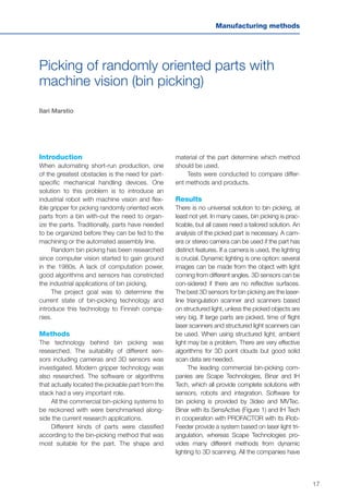
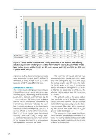
Figure 2. Corner radius of cutting surfaces with 90 degree corners on the upper and
lower surfaces [µm]. (CO2
N laser cutting results in the corner radius 1.4301 s = 0.5 mm – r
upper/lower surface = 175/162.5 µm).
1.4301
0,5 mm
1.4301
0,88 mm
M400-50A
(1)
0,52 mm
M400-50A
(2)
0,52 mm
S235
0,76 mm
S235
1 mm
DC01
0,5 mm
DX51D+Z
1 40-M-C
0,64 mm
Aluminium
1
0,16 mm
Upper surface 137,5 156,25 150 100 131,25 137,5 137,5 162,5 208,33
Bottom surface 125 156,25 131,25 68,75 112,5 131,25 100 81,25 150
0
50
100
150
200
250
Cornerradius,µm
Remote laser cutting results in good cut-
ting groove surface perpendicularity, and the
differences in perpendicularity are small.
The corner sharpness was determined by
measuring the corner radius r [µm]. The corner
radius was bigger on the upper surface than
on lower surface. The corner sharpness qual-
ity was good. The smallest corner radius was
100 µm on the upper surfaces and 69 µm on
the lower surfaces. (See Figure 2.)
Burr appears on both sides of the groove
on the upper and lower surfaces, and the burr
dimensions vary on different materials, e.g.
material 1.4301 has wider burr than the other
materials. [1]
Conclusions
Remote laser cutting demands good beam
quality in single mode lasers as well as quality
optics to reach a small focal spot and material-
vaporizing power intensity. The process works
very well on thin materials. Thicker materials
cause lower power densities and difficulties
removing liquid metal from the groove.
The laser beam power and quality, scan-
ning speed, scanning sequence repeat num-
ber and scanning repeat interval are the most
important remote laser cutting parameters. The
effective cutting speed depends significantly on
the time between scanning repeats.
In through-cut scanning, the repeat num-
ber of thin sheet metals depends more on
the thickness than the material because the
power intensity decreases when the groove
becomes deeper.
The heat effects in the material depend
on the number of scanning repeats (thickness)
and scanning intervals. A shorter repeat inter-
val reduces the scanning repeat number but
has more heat effects and widens the groove.
The groove widths are very small in remote
laser cutting because of the good beam qual-
ity. The groove is wider on the upper surface
than the lower surface, but the thickness does](https://image.slidesharecdn.com/vttresearchhighlights3fgfissuuversio-140319040805-phpapp02/85/Production-matters-VTT-in-global-trends-27-320.jpg)
![28
not have much effect on the groove width (on
thin materials).
The surface roughness varies and is
worse than, e.g., CO2
N laser cutting.
Perpendicularity is good on low (> 1 mm)
thicknesses and similar to CO2
N laser cutting.
The remote laser-cut 90 degree corners are
significantly sharper than in CO2
N laser cutting.
The corner radius depends more on the mate-
rial than the thickness (in thin materials).
The burr layer appears on both sides of
the groove on the upper surface while in CO2
N
laser cutting, the burr appears on the lower sur-
face. The burr is thicker on thicker materials. [2]
Acknowledgements
The project ‘Flexible tailored serial production
of 3D sheet metal products and new pro-
cesses of automated manufacturing’ (Joyrem)
was executed during 2009–2011 by research
groups at VTT and LUT in Lappeenranta. The
authors of this report would like to acknowl-
edge the steering group and all the companies
in the project for active steering and good
cooperation throughout the project.
References
[1] Pihlava, A. Remote laser welding of sheet
metals. Master’s thesis. Lappeenranta, Uni-
versity of Technology, Lappeenranta, 2010.
110 p. (In Finnish.)
[2] Savinainen, T., Kujanpää, V. & Salminen, A.
Internal reports of Joyrem project. VTT and
Lappeenranta University of Technology,
Finland, 2009–2011. (In Finnish.)](https://image.slidesharecdn.com/vttresearchhighlights3fgfissuuversio-140319040805-phpapp02/85/Production-matters-VTT-in-global-trends-28-320.jpg)
![29
Manufacturing methods
An interactive 3D sensor system and
its programming for target localizing in
robotics applications (Luovi)
Tapio Heikkilä and Esa Viljamaa
Due to the cost level, the production of goods in
developed countries favours shorter series over
mass production. This sets strong demands
for more flexible means of production. Interac-
tive robotics introduces high flexibility to robotic
task execution, relying on human intelligence
and understanding.
Introduction
Due to the needs for flexibility in production by
Western countries, new methods to leverage
flexibility are needed.
An interactive sensor system for robotic
applications with easy and flexible planning
and programming enables flexible feedback
from the process to the robot. This results
in cost-effective, easy-to-use and accurate
object localizing [1, 2].
The aim of the research has been to use
human intelligence and skills to reduce haz-
ardous manual work and introduce flexibility to
robotic tasks. Flexible measurement technolo-
gies with optical sensors supervised by human
operators are used to adapt to the variation in
target object locations and robot paths. This
is supported by CAD-based programming of
sensory operations.
Methods
The full use of the measurement system is
explained in Figure 1.
The localizing in the robot task execution is
based on the initial estimate of the target object
location, the set of programmed geometric refer-
ence features and the results from the interactive
measurements. The interactive measurements
(2D or 3D points) are fitted to the reference fea-
ture models and a Localizing algorithm calcu-
lates the position and orientation (pose) of the
target object. This is then loaded into the robot
controller and used to adapt the robot work
paths to the real location of the target object.
The accuracy of the measurement system
was verified with reference measurements by
an industrial level tachometer and accurately
calibrated robot.
Results
A main scientific result of the project was a
new method and tested prototype system for
interactive object localization for the needs of
flexible manufacturing. The system was easy
to use and worked as expected. The system
reached 1–2 mm relative accuracy at a sensor
(camera) distance of 5 m for the 4 m x 4 m
measured workpiece.
The novelty of the work, especially the easy
programming of the sensor tasks, lies in the use
of standard CAD tools. The full application of
the interactive sensor scheme with dynamic
formation of the measurement model in a real
experimental test environment is also new.
Discussion
The interactive sensor system has been
implemented, is working and easy to use. It
is based mostly on commercial HW and SW
tools, with an extension to estimate planned
feature parameters and an estimation of the
target object location during task execution.](https://image.slidesharecdn.com/vttresearchhighlights3fgfissuuversio-140319040805-phpapp02/85/Production-matters-VTT-in-global-trends-29-320.jpg)
![31
Manufacturing methods
References
[1] Heikkilä, T., Ahola, J.M., Viljamaa, E., Järvi-
luoma, M. An interactive 3D sensor system
and its programming for target localizing
in robotics applications. In: Proceedings
of the IASTED International Conference on
Robotics, Robo 2010, Phuket, Thailand,
24–26 November, 2010. Pp. 89–96.
[2] Heikkilä, T., Ahola, J.M., Viljamaa, E.,
Järviluoma, M. Vuorovaikutteisen 3D
mittausjärjestelmän CAD-perusteinen
ohjelmointi ja liittäminen robotin ohjauk-
seen. Automaatio 2011, Helsinki, Finland,
15–16 March, 2011. (In Finnish.)](https://image.slidesharecdn.com/vttresearchhighlights3fgfissuuversio-140319040805-phpapp02/85/Production-matters-VTT-in-global-trends-31-320.jpg)
![44
of 5 to 50% of the bulk Cu conductivity with
post-sintering temperatures in the range of
120 to 300ºC, and the DWTS copper had a
conductivity of about 40% of the bulk copper
conductivity. The DWTS spinel has good elec-
trical insulating properties on metal surfaces
thus providing the dielectric properties for dif-
ferent sensor structures.
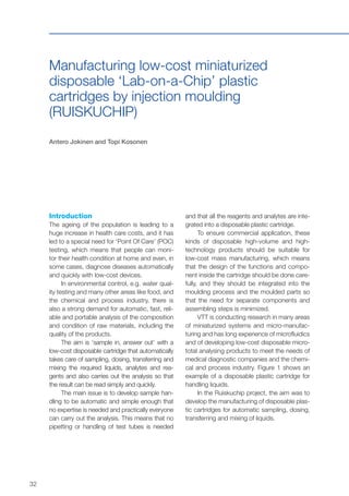
To demonstrate the feasibility of DWP, sil-
ver paste was used to fabricate conductive
structures on polymer substrates. The other
demo consisted of both 2D and 3D polymer
structures. A 3D structure dispensed for the
polycaprolactone (PCL) polymer is presented
in Figure 2.
Different sensor structures were fabri-
cated and tested with the DWTS technique.
Thermocouples (TC) sprayed on 2D samples
were tested in the laboratory giving reasona-
ble repeatability. Figure 2 shows TCs depos-
ited on curved surfaces for temperature dem-
onstration purposes. The strain gauges were
fabricated on 2D samples and tested by Mes-
oScribe Technologies Inc. The strain gauges
performed in a similar way to those fabricated
by MesoScribe. However, some needs for
more tuning and material improvement were
distinguished for more stable and repeatable
measurement results. Strain gauges to meas-
ure torque were also fabricated on a cylindri-
cal shaft. Since the spray gun is manipulated
by a robot, it is possible to make deposits on
complicated component structures. The sen-
sors were evaluated with a repeated pulsating
load. The results showed good performance
for the sensors compared with the reference
sensors and proved the feasibility of using
DWTS technology to fabricate stain gauges
for, e.g., torque measurement [1].
Discussion and conclusions
The results and demo evaluations showed
good performance by DW materials and struc-
tures. Several demonstrations provided good
insights into the capability of techniques and
proved the huge potential the DW techniques
have for future manufacturing. However, more
research and development of the material
used is needed in order to improve the mate-
rial performance.
Exploitation potential
As Direct Write (DW) technology enables new
production techniques and solutions for elec-
tronics and the integration of electronics onto
mechanical components it has a wide applica-
tion field and huge potential in the future. The
DWP technique enables miniaturization in elec-
Figure 1. (a) The DWTS manufacturing cell with a 6-axis robot. (b) The DWP (nScrypt)
CAD/CAM compatible facility with a two pump system.
a) b)](https://image.slidesharecdn.com/vttresearchhighlights3fgfissuuversio-140319040805-phpapp02/85/Production-matters-VTT-in-global-trends-44-320.jpg)
![45
Manufacturing methods
tronics as well as a generation of 3D electronics.
The new technique can also shorten the pro-
duction chain and provide savings in component
production. With DW, electronic components,
such as sensors, wirings and antenna struc-
tures, can be fabricated directly onto surfaces
during machine and instrument manufacture. It
is also possible to integrate the DWTS facility as
one part of the production chain. The sensors
and other electric components fabricated with
DWTS are robust and can thus provide sensor-
ing solutions for harsh conditions.
Acknowledgements
The project work was carried out by the VTT
personnel Mika Jokipii, Virpi Kupiainen, Sini
Metsä-Kortelainen, Jukka Paro, Kimmo Ruu-
suvuori, Seppo Vasarainen and Jukka Vuorio.
Their effort in the project and the financial sup-
port of Tekes, VTT, Andritz, ELE Products,
Gemalto, Metso Automation, Pulse and Wärt-
silä are greatly appreciated.
References
[1] Tervo, J., Paro, J., Ruusuvuori, K. & Ron-
kainen, H., Plasmaruiskutus sulautettujen
antureiden valmistusmenetelmänä. Pro-
maint 1, 2012, pp. 52–45. (In Finnish.)
a) b)
Figure 2. (a) Thermocouples fabricated on curved surfaces by the DWTS technique. (b)
3D structures dispensed from PCL with the DWP technique.](https://image.slidesharecdn.com/vttresearchhighlights3fgfissuuversio-140319040805-phpapp02/85/Production-matters-VTT-in-global-trends-45-320.jpg)


![51
Factory and enterprise systems
Optimization of autonomous production
cells – real time production intelligence
(ATOR)
Juhani Heilala and Jari Montonen
VTT has developed customizable simulation
software for use in production planning and
capacity control for discrete part-manufac-
turing. Based on the production information,
GeSIM simulates and visualizes resource use,
work in process and delivery accuracy in the
production system.
Introduction
Agile, fast and flexible production networks
are a must for companies facing today’s global
competition. Delivering on the stated order
date is the key element to customer satisfac-
tion. In lean manufacturing, material stocks
are kept as small as possible, while expensive
resource use is kept as high as possible. One
important decision in production planning is the
scheduling and synchronization of activities,
resources and material flow. The produc-
tion personnel must seek a balance between
customer orders and limited resources. The
connections between manufacturing systems
and processes are becoming more complex
and the amount of data required for decision-
making is growing.
Production planners need accurate and
dynamic models of production, i.e. simulation
models that use a production network and real
shop floor data in near real time. The basic
idea is to combine the strengths of automatic
data analysis, calculations and simulation re-
sults with the visual perception and analysis
capabilities of the human user who makes the
final decisions. The use of simulation with an
easy-to-use graphical user interface provides
tools and methods for a manufacturing sce-
nario evaluation, scheduling optimization and
production planning even for simulation non-
experts (Figure 1).
Methods
Discrete-event simulation (DES) has mainly
been used as a production system analysis tool
to evaluate new production system concepts,
layout and control logic. Recent develop-
ments have made DES models feasible for
use in the day-to-day operational produc-
tion and planning of manufacturing facilities
[1]. Manufacturing system simulation with
planned future operations, relevant resource
and material data is a suitable management
and evaluation tool to help production man-
agers. These dedicated ‘as built’ simulation
and calculation models provide manufactur-
ers with the ability to evaluate the capacity of
the system for new orders, unforeseen events
such as equipment downtime, and changes
in operations. The major challenges for such
system (e.g. GeSIM) development are:
1. Data integration: Manufacturing operations
planning is typically performed in a heterogene-
ous information system environment. Examples
of such systems include: Enterprise Resource
Planning (ERP), Manufacturing Execution Sys-
tem (MES), job shop supervisory and data
acquisition systems, maintenance management
systems, etc. GeSIM does not replace these
existing systems; they remain in place as parallel
systems, serving as sources of information for
decision-making and means to implement the
decisions. There is a need to transfer and share](https://image.slidesharecdn.com/vttresearchhighlights3fgfissuuversio-140319040805-phpapp02/85/Production-matters-VTT-in-global-trends-51-320.jpg)
![52
data between GeSIM and other manufacturing
software applications. Custombuilt proprietary
interfaces do require customization, but GeSIM
is quite flexible.
2. Automated simulation model creation
and updates: There is a need for perma-
nent, alwayson, synchronized factory models
or models that can be created automatically
on demand from ERP and other interoper-
able data sources and that are used for the
manufacturing process and operations plan-
ning. GeSIM does support automated model
building using selected data sources as input.
3. The visualization of results for interactive
and effective decision-making: Simulation
analysis produces a great deal of numerical
??
??
PAST
NOW
Customer
orders
Limited
Resources
New orders Late orders
CapacityDelivery time
LOAD
Scheduling
Subcontracting
overtime/shifts
Rescheduling
of old orders
vs. CAPACITY
Figure 1. Simulation-based production planning.
information consisting of tables, listings and
reports. It is difficult for a human decision-maker
to locate the relevant pieces of information.
Thus, the simulation results have to be pre-
sented in a visually effective way to speed up
and improve the way the results will be under-
stood. Different users require, or are allowed
access to, different types of information, or the
same information is presented differently. Time
is an important factor in defining how much and
what kind of data should be aggregated for the
upper levels of the organization: a manager
cannot afford to be ‘swimming in data’ when
making a quick decision.
The efforts at VTT to overcome these
challenges during the ATOR project are shown
[1, 2, 3, 4].](https://image.slidesharecdn.com/vttresearchhighlights3fgfissuuversio-140319040805-phpapp02/85/Production-matters-VTT-in-global-trends-52-320.jpg)
![54
with a real industrial case study [2, 4], and the
standardization landscape was evaluated [3].
Discussion and exploitation
potential
Some of the benefits of implementing an
operational simulation scheduling system (e.g.
GeSIM) include: less effort to plan day-to-day
scheduling, customer order due date con-
formance, synchronization of flow through the
plant, minimization of setups/changeovers,
early warnings of potential problems, checks of
critical resources and materials and, naturally,
a ‘what-if’ scenario analysis for capacity plan-
ning. The presented methodology harmonizes
the decision-support system for production
and capacity management and uses near
real time production status information. This
type of operational decision-support system
has many potential users, from operators on
the production line to the plant manager and
even upper management. The use of this kind
of method can be applied to extended enter-
prises. External resources can also be shown,
if the necessary information is available.
Acknowledgements
The research was carried out as part of
the national research project ‘Optimiza-
tion of autonomous production cell – real
time production intelligence’ (2009–2011).
The industrial partners, VTT and TEKES (the
Finnish Funding Agency for Technology and
Innovation) have funded the work carried out
by VTT. The project was part of the national
SISU 2010 – Innovative Manufacture program.
References
[1] Heilala, J., Montonen, J., Järvinen, P. &
Kivikunnas, S. 2010. Decision Support
Using Simulation for Customer-Driven
Manufacturing System Design and
Operations Planning. (Chapter 15). In:
Devlin, G. (ed.). Decision Support Sys-
tems Advances in. Intech. Pp. 235–260.
http://www.intechopen.com/books/
decision-support-systems-advances-in/
decision-support-using-simulation-for-
customer-driven-manufacturing-system-
design-and-operations-pla.
[2] Heilala, J., Montonen, J., Järvinen, P.,
Kivikunnas, S., Maantila, M., Sillanpää, J.
& Jokinen, T. 2010. Developing Simulation-
Based Decision Support Systems for
Customer-Driven Manufacturing Operation
Planning. Proceedings of the 2010 Winter
Simulation Conference, WSC ‘10, Baltimore
Marriot Waterfront, Baltimore, MD, USA, 5–8
December, 2010. Johansson, B., Jain, S.,
Montoya-Torres, J., Hugan J. & Yücesan, E.
(eds.). IEEE. Pp. 3363–3375. http://www.
informs-sim.org/wsc10papers/311.pdf.
[3] Kivikunnas, S. & Heilala, J. 2011.
Tuotantosimuloinnin tietointegraatio. Stan-
dardikatsaus. VTT Working Papers 172.
VTT, Espoo, Finland. 29 p. http://www.vtt.fi/
inf/pdf/workingpapers/2011/W172.pdf. (In
Finnish.)
[4] Heilala, J., Montonen, J., Usenius, T.,
Kuula, T., Maantila, M. & Sillanpää, J. User-
centric development of simulation based
manufacturing operation planning and
scheduling system. Proceedings – 2011
IEEE International Symposium on Assembly
and Manufacturing, ISAM 2011, Tampere,
Finland, 25–27 May, 2011. IEEE Com-
puter Society, p. 5942346. Doi: 10.1109/
ISAM.2011.5942346.](https://image.slidesharecdn.com/vttresearchhighlights3fgfissuuversio-140319040805-phpapp02/85/Production-matters-VTT-in-global-trends-54-320.jpg)
![62
Development of a manufacturing
information portal for SMEs in traditional
industries (Eskale)
Jukka Hemilä
Abstract
Today, markets offer a variety of enterprise
information systems for manufacturing indus-
tries. In many cases, these systems are
independent solutions without any communi-
cation links between them. In global business,
in which SMEs in the manufacturing industry
are today deeply involved, the requirements
for information sharing are increasing. Infor-
mation should be seamlessly available at all
times for enterprises as a whole, as well as
for the individual employees’ needs. SMEs are
facing the challenge of needing a common
ICT solution to support their business func-
tions; however, the applications available on
the market are too complex for the purposes
of an SME and any tailor-made solution tends
to be too expensive for SMEs. This challenge
has been the motivation for this research and
development project, which aims to develop a
supply-chain-oriented information platform for
SMEs in the manufacturing industry.
Introduction
In this study we identified two ways for SMEs
to take part in the global supply chain: 1) by
supplying their own products to the global
markets, and 2) by being a supplier to global
customers. To ensure material or product
availability in both cases, SMEs need informa-
tion from the customer side, but they should
also inform the customer about production
and deliveries. The manufacturing SME’s
needs for information and its challenging role
in global supply chains was the starting point
for our ESKALE (Trans-European Sustain-
able Knowledge-Based Manufacturing for
Small and Medium Sized Enterprises in Tra-
ditional Industries) project. The needs of the
companies being studied are the basis of the
requirements for the development of the Man-
ufacturing Information Portal (MIP).
Methodology
This study was based on Yin’s multiple case
study definition [1]. We have developed a
common framework for analysing end-user
companies’ needs. From the discovered
needs, we developed a new method for han-
dling information management in SMEs in the
manufacturing industry. That method was
tested with case study companies in order to
see if and how it fits their needs. After the case
test, the software developer created a work-
ing demo and, finally, a real solution for market
needs.
Information systems for SMEs in
the manufacturing industry
For the management of production-related
information, SMEs could have Enterprise
Resource Planning (ERP) systems. SMEs could
have different operational tools for product
design, CAD/CAM systems. The Product Data/
Lifecycle Management (PDM/PLM) system is
used for tracking the configuration of the part,
billing the material, tracking the revisions and
history of the design, and building the condi-
tions. The product integration between the
CAD and PDM systems improves the quality
of design and the response time to market.
Customer Relationship Management (CRM) is](https://image.slidesharecdn.com/vttresearchhighlights3fgfissuuversio-140319040805-phpapp02/85/Production-matters-VTT-in-global-trends-62-320.jpg)
![63
Factory and enterprise systems
a business strategy aimed at organizing and
handling the business actions connected to
customer relationships through the whole life
cycle of the partnership with customers [2].
CRM systems are used to support marketing,
sales and service processes. Supply Chain
Management systems are used to handle and
manage supply chains and, especially, the sup-
ply processes. Good SCM systems include
acquisition (source), manufacturing (make) and
logistics (deliver), but there could also be ware-
housing (store) and markets (sell). SCM systems
are not widely used in small and medium-sized
manufacturing companies. The SME usually
only has production-related information tools,
not supply chain-level management tools.
One method for analysing ICT in SMEs
in the manufacturing industry is the process
of flow analysis. Okrent and Vokurka [3] have
defined the six core business processes in
ERP systems: quote to cash, procure to pay,
plan to perform, manufacturing operations,
product life cycle and financial management
(Figure 1). In our context of the traditional
manufacturing industry there could be individ-
ual ICT tools to manage these processes and
not only the ERP.
Planning and forecasting
Manage Finances
Order Flow
Manage Inventory
Manage Product Lifecycle
Manage Production
6
1
2
5
3
4
Plan to Perform
Financial Support
Quote to Cash
Manufacturing
Operations
Product Life Cycle
The lack of an existing common solu-
tion for supply chain-level in-formation, espe-
cially according to the needs of SMEs, was
one of the main sources of motivation for the
ESKALE project.
Development and requirements
analysis of end-user companies
Four end-user companies were involved in
our project. Two of them were from Finland
and two from Germany. Three of the end-user
companies were traditional manufacturers and
one a logistics service provider. All manufac-
turers have their own products for the global
and national markets, and all of the final prod-
ucts from the end-user companies could be
sold directly to distributors; additionally, they
all took the role of supplier in business with
bigger global customers.
The analysis of end-user requirements and
development challenges was carried out by an
‘as-is’ and ‘to-be’ process mapping analysis.
The starting point of the analysis was the defi-
nition of the ‘process reference model’ (PRM).
We created a common template for business
processes in manufacturing companies. Then,
with the end-user companies, their business
Figure 1. Key business flows (Modified from [3]).](https://image.slidesharecdn.com/vttresearchhighlights3fgfissuuversio-140319040805-phpapp02/85/Production-matters-VTT-in-global-trends-63-320.jpg)
![64
processes are described by selecting process
phases from the PRM. In this way we created
a common understanding of the business envi-
ronments in end-user companies. The next
phase was the analysis of existing information
tools in end-user companies. That analysis was
carried out by first defining the ‘information ref-
erence model’ (IRM), and then by fulfilling the
IRM with end-user companies.
Discussion and conclusions
Globally operating companies should manage
all supply chain processes (purchasing, mak-
ing, delivering and planning), which requires
a large amount of information. Lefebvre and
Lefebvre [4] argue that SMEs can be more
innovative than large organizations because
they are less bound by bureaucracy and
cumbersome organizational systems. SMEs
will be able to be more competitive as they
can introduce new technologies quickly, both
manufacturing and supporting technologies.
Investment in new technologies could be
equally hard for SMEs however, due to their
lack of resources. Companies have various
sets of individual solutions without communi-
cation links to each other. The ESKALE project
developed a solution called the Manufacturing
Information Portal targeted at traditional SMEs
in the manufacturing industry. The develop-
ment of the MIP consisted of an existing
business process analysis, ICT requirement
analysis and literature survey of existing solu-
tions targeted at manufacturing companies. All
the ideas from the process analysis and the lit-
erature survey were included in the operational
and technical requirements of the MIP. The
ESKALE end-user companies implemented
and evaluated the new MIP. The software pro-
vider was responsible for further development
and commercialization of the MIP.
Acknowledgement
ESKALE was a transnational research pro-
ject funded by the Finnish Funding Agency
for Technology and Innovation (Tekes, FI) and
Projektträger Forschungszentrum Karlsruhe
(PTKA, DE). The project consisted of four end-
user SMEs: Hubstock Oy (FI), Ovitor Oy (FI),
Gleistein Ropes (DE) and Bischoff International
AG (DE), and one software provider, CAS soft-
ware AG (DE). Two research institutes were also
involved in the project: the Technical Research
Centre of Finland (VTT, FI) and the Bremen Insti-
tute for Production and Logistics (BIBA, DE).
References
[1] Yin, R. Case study research: design and
methods. 3rd edition, Applied social
research methods series; v. 5. Sage Publi-
cations, Inc., 2003.
[2] Hemilä, J. Information technologies for
value network integration. VTT Research
Notes 2149. VTT, Espoo, Finland, 2002.
[3] Okrent, M., Vokurka, R. Process mapping
in successful ERP implementations. Indus-
trial Management & Data Systems, Vol.
104, No. 8, 2004, pp. 637–643.
[4] Lefebvre, E. & Lefebvre, L. Firm Innovative-
ness and CEO Characteristics in Small
Manufacturing Firms. Journal Engineering
and Technology Management 9(3–4), 1992,
pp. 243–272.](https://image.slidesharecdn.com/vttresearchhighlights3fgfissuuversio-140319040805-phpapp02/85/Production-matters-VTT-in-global-trends-64-320.jpg)
![67
Factory and enterprise systems
dures: find out how potential, realistic changes
influence the economic results, which depends
on the customer structure, product specifica-
tions, properties of wood raw material, manu-
facturing technology, capacities, etc. Very good
modelling methods and data bases have been
created in SisuPUU in order to study new com-
pany-specific production systems.
Publications
Lyhykäinen, H., Mäkinen, H., Mäkelä, A. &
Usenius, A. Predicting lumber grade and by-
product yields for standing scots pine trees. In:
Dykstra, D.P. & Monserud, R.A. (eds.). Forest
Growth and Timber Quality: Crown Mod-
els and Simulation Methods for Sustainable
Forest Management. USDA Forest Service –
General Technical Report Report PNW-GTR.
Vol. 791, 2009, 157–166.
Usenius, A. Adaptive and flexible production
systems for woodworking industry. Proceedings
Abstract. IUFRO All Division 5 Conference, Tai-
pei, Taiwan, 29 October – 2 November, 2007.
Usenius, A. Flexible and Adaptive Produc-
tion Systems for Manufacturing of Wooden
Components. Proceedings Volume 1 of 18th
International Wood Machining Seminar, Van-
couver, Canada, 7–9 May, 2007, pp. 187–196.
Usenius, A. Puutuoteteollisuuden jalostusketju-
jen optimointi metsästä tuotteeksi (Optimization
of conversion chains in wood products industry
– from the forest to the end products). Finnish
Operations research Society, INFORS 1/2007,
pp. 20–29. (In Finnish.)
Usenius, A. & Heikkilä, A. WoodCIM® – model
system for optimization activities through-
out supply chain. COST E 44 Conference
proceedings on Modelling the Wood Chain
Forestry – Wood Industry – Wood Products
Markets. Helsinki, Finland, 17–19 September,
2007. Pp. 173–183.
Usenius, A., Heikkilä, A., Song T., Fröblom J.
& Usenius T. Joustavat ja itseoppivat tuotan-
tojärjestelmät sahateollisuudessa (Flexible and
Adaptive Manufacturing Systems for Sawmill
Industry). VTT Research Notes 2544. VTT,
Espoo, Finland, 2010. 217 p. http://www.vtt.fi/
inf/pdf/tiedotteet/2010/T2544.pdf. (In Finnish.)
Usenius, A., Heikkilä, A., Song, T. & Usenius, T.
Improvement potential of value yield in sawmill-
ing through scanning of internal knot structure
of round wood [keynotes speak]. Proceedings
of the COST E 53 Conference and meeting
in Lisbon, Portugal, 22–23 October, 2009.
Santos, J.A. (ed.). Economic and Technical
aspects of quality control for wood and wood
products. COST, European Cooperation in the
field of Science and Technical Research. 20 p.
Usenius, A., Heikkilä, A. & Usenius, T. Future
Processing of Wood Raw Material. Key note
paper. Proceedings of the 20th International
Wood Machining Seminar. Skellefteå, Swe-
den, 7–10 June, 2011.
Usenius, A., Heikkilä, A., Usenius, T. & Hol-
mila, P. Sawmilling and Sawing Process in the
Future. Proceedings of the final conference of
COST Action E53: Quality control for wood
& wood products, Edinburgh, UK, 4–7 May,
2010. Incorporating the European Wood Dry-
ing Group workshop. Pp. 163–172.
Usenius, A., Song, T. & Heikkilä, A. Optimiza-
tion of activities throughout the wood supply
chain. Proceedings International Scientific
Conference on Hardwood Processing. Que-
bec City, Canada, 24–26 September, 2007.
Pp. 199–205.](https://image.slidesharecdn.com/vttresearchhighlights3fgfissuuversio-140319040805-phpapp02/85/Production-matters-VTT-in-global-trends-67-320.jpg)
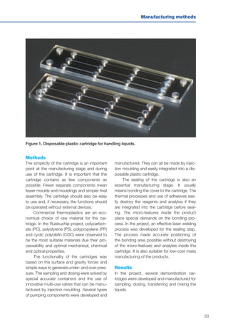
![69
Factory and enterprise systems
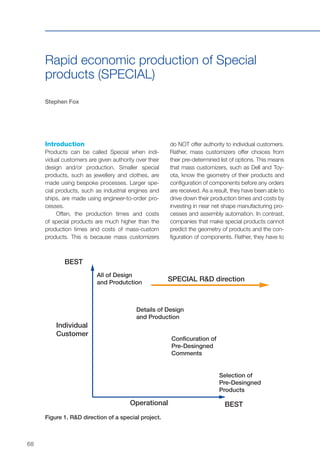
Figure 2. Enabling distributed capture and communication of manual skills [3].
Formulating
Training
(ITS at training centres)
Training
(JITT in site offices)
Supplementing
(PUI at workface)
SkillWiki
Knowledge base
on server
wait to find out what each individual customer
wants. This means that investments in near net
shape manufacturing processes and assembly
automation are often neither technically feasible
nor economically viable.
Consequently, the companies that make
special products continue to be reliant on
subtractive manufacturing processes, such
as cutting and drilling, and on the manual
skills of human operatives. Moreover, the
planning and costing of special production is
extremely challenging because each product
has to be engineered individually. This means
that standard bills of materials and process
routes cannot be developed once and used
repeatedly. As illustrated in Figure 1, the
R&D direction of the Special project was to
improve the speed and economy of special
production.
Results
Five Finnish companies that offer special
products and face global competition partici-
pated in the SISU project SPECIAL. Experts
from VTT contributed to a range of process
improvements within these companies. In
particular, dynamic systems modelling and
activity-based costing exercises were carried
out to improve planning and costing [1].
Foreign collaboration focused on develop-
ing innovative solutions to the companies’ reli-
ance on the manual skills of human operatives
[2]. Research and development was carried
out with the Fraunhofer Institute in Germany
and Stanford University in USA. As illustrated
in Figure 2 [3], due to the limited potential of
assembly automation in special production,
innovation has focused on enabling the real
time communication of skill knowledge with-
out human instructors.](https://image.slidesharecdn.com/vttresearchhighlights3fgfissuuversio-140319040805-phpapp02/85/Production-matters-VTT-in-global-trends-69-320.jpg)
![70
Exploitation potential
Special Products are growing in importance
as customers demand increasingly individual
goods. The range of solutions developed
during the Special Project can enable more
companies to make more money from offering
greater authority to individual customers.
References
[1] Fox, S., Jokinen, T., Lindfors, N. & Ylen, J.-P.
Formulation of robust strategies for pro-
ject manufacturing business. International
Journal for Managing Projects in Business,
2(2), 2009, pp. 217–237.
[2] Fox, S. The importance of information and
communication design for manual skills
instruction with augmented reality. Journal
of Manufacturing Technology Management,
21(2), 2010, pp. 188–205.
[3] Fox, S., Ehlen, P. & Purver, M. Enabling dis-
tributed communication of manual skills.
International Journal for Managing Projects
in Business, 4(1), 2011, pp. 49–63.](https://image.slidesharecdn.com/vttresearchhighlights3fgfissuuversio-140319040805-phpapp02/85/Production-matters-VTT-in-global-trends-70-320.jpg)
![71
Factory and enterprise systems
Merging paradigms: engineering for a
managed product life cycle (systems
engineering)
Göran Granholm
Running a successful business in a world of
constant change is a great challenge for all
enterprises, not least within the manufacturing
industry. Globally networked organizations do
their best to adjust to new situations in order
to launch new products fast and efficiently to
a global market with rapidly changing cus-
tomer preferences and fierce competition. The
required speed of product development and
production together with continuously evolv-
ing enterprise networks and business mergers
generates an environment in which long-term
strategic planning and well-managed prod-
uct processes are difficult to establish and
maintain. The risk is that processes remain
suboptimal, leading to decreased productiv-
ity, quality problems and, in the end, higher
cost of ownership for the customer. In order to
deal with these challenges, a holistic approach
must be applied that considers all aspects of
the product life cycle from concept to dis-
posal. This must be based on a management
system for dealing with product and process
data throughout the life cycle.
Introduction
A project called ‘Systems Engineering – PLM
integration’ has been launched to deal with
two seemingly different views of the product
process. With a background in defence and
aerospace sectors, Systems Engineering (SE)
has a long tradition as a systematic approach
to developing high complexity products. One
of the cornerstones of SE is the focus on sys-
tematic verification and validation against a
comprehensive set of requirements covering
all phases of the product’s life. PLM, or prod-
uct life cycle management, on the other hand,
has developed from the need to manage
product- and process-related data throughout
the product’s life.
Essentially, SE focuses on the pro-
cess whereas PLM focuses on the method
and data. Consequently, Systems Engineer-
ing has remained more theoretical while the
current understanding of PLM is still largely
based on IT and PLM systems [1]. Recently,
SE and PLM have both been developing
towards a more holistic view of the product
life cycle (Figure 1). Despite increasing over-
laps of scope, SE and PLM have not fre-
quently been studied together as synergistic
approaches. This is now rapidly changing as
an increasing number of PLM system provid-
ers have introduced support for SE-based
processes in their products.
A prerequisite for increased automation
and efficiency is a harmonization of processes,
data representations and supporting tools.
One of the most significant developments
relating to the interoperability of tools and the
integration of different engineering disciplines
is the increasing use of models [2]. The mod-
els range from conceptual representations to
functional simulation models and virtual real-
ity. The development and standardization of
models has been treated in some recent pub-
lications, mainly from a technical point of view
[3, 4]. In addition to the technical issues, the
adoption of these emerging tools and meth-
odologies throughout the networked enter-
prise remains a challenge.](https://image.slidesharecdn.com/vttresearchhighlights3fgfissuuversio-140319040805-phpapp02/85/Production-matters-VTT-in-global-trends-71-320.jpg)
![73
Factory and enterprise systems
References
[1] Sääksvuori, A. PLM Vision 2016 and
Beyond, Sirrus Publishing, April, 2011.
[2] International Council on Systems Engineer-
ing. INCOSE Systems Engineering Vision
2020, INCOSE-TP-2004-004-02, Septem-
ber, 2007.
[3] Fasoli, T., Terzi, S., Jantunen, E., Korte-
lainen, J., Sääski, J. & Salonen, T.
Challenges in Data Management in Prod-
uct Life Cycle Engineering. The 18th CIRP
International Conference on Life Cycle
Engineering, Technische Universität Braun-
schweig, Braunschweig, Germany, May
2–4, 2011.
[4] Alanen, J., Vidberg, I., Nikula, H., Papa-
konstantinou, N., Pirttioja, T. & Sierla, S.
Engineering Data Model for Machine
Automation Systems. VTT Research Notes
2583. VTT, Espoo, Finland, 2011. 129 p.
http://www.vtt.fi/inf/pdf/tiedotteet/2011/
T2583.pdf.](https://image.slidesharecdn.com/vttresearchhighlights3fgfissuuversio-140319040805-phpapp02/85/Production-matters-VTT-in-global-trends-73-320.jpg)
![74
Automation isles for the future (TUAUSA)
Sauli Kivikunnas, Timo Salmi, Topi Pulkkinen and Mikko Sallinen
We present a concept for short-series pro-
duction using industrial robots and advanced
control systems and illustrate the operation
in the pilot case. We call and define this sys-
tem as ‘isles of automation’. The concept is
beyond the current robot work cells by the
properties of flexibility, reconfigurability, con-
text awareness and programmability. In the
concept, modules are defined for program-
ming, sensing, material handling and flow as
well as communication. The overall architec-
ture defines how these modules work together.
Introduction
Modern production is facing growing require-
ments for flexibility and productivity. Product
life cycles are becoming shorter, the variety of
products is increasing and the production costs
should be reduced. At the same time, when the
pressure to automate has risen, it is more dif-
ficult with well-established technologies. There
is an obvious demand for new solutions that
will open up new possibilities for flexibility. The
requirements for short-series production are
high-level flexibility for production changes and
on-line adaptation for deviations in the work-
pieces. The production platform should be as
reconfigurable as possible. This means that the
requirements of flexibility concern solutions to
hardware, software and communication. Fea-
tures like reconfigurability, modularity, adaptivity
and autonomy are desirable in all these solu-
tions. The flexibility needs are mostly based on
the parameters of batch size, the total volume of
the product and the width of the differences in
the part geometries. In modern manufacturing
devices and systems, flexibility and versatility of
automated production are largely defined by a
priori order, task planning and programming.
This is extended by their level of communica-
tion and autonomy to react in real time to initially
unforeseen part tolerances and position devia-
tions, not to mention, the escalating problem
of scheduling in a highly dynamic environment.
However, operations like this are too often far
from the reality.
Methods
The concept of ‘isles of automation’ for short-
series production has a modular structure, and
it is realized as a highly flexible and controlla-
ble robotized system. It exploits the features
of ubiquitous technology, including flexibility,
adaptivity, context awareness and reactivity,
which are beyond the current automation solu-
tions. The production system easily adapts
to new products or product variants and to
deviation in workpieces. The data acquisition
presents new possibilities when open inter-
faces are offered down to the sensor level. This
means that sensors offer services and are vis-
ible to the whole control system. Sensors can
be used for on-line purposes such as control
but also off-line monitoring such as quality
control and prognosis of the maintenance of
the machines. This kind of features cannot be
found in the current systems. The development
of manufacturing systems has had two main
approaches: Flexible Manufacturing Systems
(FMS) and Reconfigurable Manufacturing Sys-
tems (RMS) [1]. The concept presented here
has adapted features from both. The basic ele-](https://image.slidesharecdn.com/vttresearchhighlights3fgfissuuversio-140319040805-phpapp02/85/Production-matters-VTT-in-global-trends-74-320.jpg)
![75
Factory and enterprise systems
ment of the automation island is an industrial
robot equipped with different kinds of exter-
nal sensors and auxiliary devices combining
mechanics, sensor technology and software
together with intelligence in the form of a con-
trol and decision-making system. This gives
high-level flexibility in terms of programmabil-
ity, reusability and price. The operation of the
automation island (see Figure 1) is managed
by control software, the ‘isle manager’, which
controls the execution of tasks. It also manages
the sensing and reactions to unexpected situa-
tions in the robot cell. The work is carried out by
communicating with distributed modules and
providing the ways to carry out the tasks. The
‘isle manager’ is located in the application layer
in the production cell and communicates within
a production call and workflow manager in the
engineering resources. [2, 3]
Results
The proposed concept was demonstrated in a
pilot case [4] that considered the implementa-
tion of different parts of the concept, i.e., the
production cell and engineering resources. The
aim of the demonstration task was to deburr
the bevels of a work object. As source informa-
tion, there was a 2D drawing of the work object
and information on the bevels. In the engineer-
Figure 1. Automation island.
Off-line programming
Simulation
Virtual Sensors
Order parameters
3D CAD
Materials
Control Layer
Mechanics Layer
Manipulator
Fixtures, grippers,
material handing devices, ...
Monitoring Data
Final Products
Learnig
Quality Management
Harware CommunicationSensors
Adaption Software
ing resources, the programming of the robot
motion paths was based on 2D CAD draw-
ings. Sensing planning can also be carried out
for the localization measurements of the work
object. For the robot programming, a converter
was developed to transform the 2D CAD data
into 3D format. In the demonstration, the task-
related tool tags were automatically generated
for the surface of the CAD model, after which
they were transformed into paths for the robot.
This phase was supported by a robot motion
path planner that calculated the paths for the
robot motion such that all the points were
reachable in a same joint configuration. Engi-
neering resources would generate programs for
the application layer in the production cell. This
robot programming demonstration was carried
out in the VTT laboratory. We used the ENVI-
SION off-line programming tool by Delmia for
visualizing the virtual robot cell and the trans-
formation of the work object from 2D to 3D
data. As a robot, we used the KUKA KR150-
L110 industrial robot, and the deburring of the
bevelling was done by a tool emulator. In the
demonstration, we were content to show that
the interfacing between the different parts of
the system could easily be done. The genera-
tion of motion paths from 2D data was also
successful.](https://image.slidesharecdn.com/vttresearchhighlights3fgfissuuversio-140319040805-phpapp02/85/Production-matters-VTT-in-global-trends-75-320.jpg)
![76
Conclusions and exploitation
potential
We presented a concept for a short series of
manufacturing. The concept defines a system
structure composed of engineering resources
and production cells. We described the content
of these in detail and illustrated a demonstra-
tion case in the laboratory in which selected
parts of the concept were implemented in a
robot cell. The demonstration gave very prom-
ising results on the usability of the concept. The
overall idea behind it is to be able to respond
to very challenging manufacturing problems
to automatically process complicated objects
and carry out reconfigurations between the
products. In the future, the concept will also be
implemented in several demonstration cases in
different application areas. We can use addi-
tional tests to obtain feedback on the usability
of the concept and iteratively improve it. In the
future, the concept will also serve as a tool for
design engineers to support the design of new
flexible robot systems.
References
[1] Maraghy, H.A. Flexible and reconfigurable
manufacturing systems paradigms. Inter-
national Journal of Flexible Manufacturing
Systems 17, Springer Science Business
Media, 2006. Pp. 261–276.
[2] Salmi, T., Haataja, K., Sallinen, M., Göös, J.
& Voho, P. Isles of automation – require-
ments and solutions for a high flexible
concept of robotic systems. 2nd Interna-
tional Conference on Changeable, Agile,
Reconfigurable and Virtual Production
(CARV 2007). Toronto, Canada, 22–24 July,
2007. Pp. 894–903.
[3] Sallinen, M., Heikkilä, T., Salmi, T., Kivi-
kunnas, S. & Pulkkinen, T. A concept for
isles of automation: ubiquitous robot cell
for flexible manufacturing. International
Conference on Control, Automation and
Systems, COEX, Seoul, Korea, 14–17 Octo-
ber, 2008. IEEE. Pp. 2246–2250.
[4] Pulkkinen, T., Heikkilä, T., Sallinen, M., Kivi-
kunnas, S. & Salmi, T. 2D CAD based robot
programming for processing metal profiles
in short series manufacturing. International
Conference on Control, Automation and
Systems, COEX, Seoul, Korea, 14–17 Octo-
ber, 2008. IEEE. Pp. 156–162.](https://image.slidesharecdn.com/vttresearchhighlights3fgfissuuversio-140319040805-phpapp02/85/Production-matters-VTT-in-global-trends-76-320.jpg)
![77
Factory and enterprise systems
Ubiquitous manufacturing concept for
SMEs (Umanu)
Mikael Haag
Introduction
The Umanu research studied the impact and
applications of the ubiquitous manufacturing
concept. In this sense, ubiquitous manufactur-
ing means the usage and utility of ubiquitous
computing concepts and technologies in a
manufacturing environment. Simply put, this
means embedding more intelligence into
objects on the production line, making them
communicate and using all the data this gen-
erates to further enhance the functionality and
visibility of the production.
Methods
The basis of the ubiquitous manufacturing
system is that all single key objects and pro-
cesses also have a digital identity/identifier.
The information relating to them can therefore
easily be retrieved from the database, and all
the relevant real world information should also
be tracked and stored into these same data
models. Some example queries that a system
like this could handle are to find all of a certain
type of tool in the plant or the exact location
and stage of a single order.
The availability of all this information in digi-
tal form has been regarded by various sources
with various terms, such as real-world visibil-
ity [1] or high resolution management [2]. This
information supplied by the manufacturing pro-
cesses is generated by discrete events and
can include data such as a timestamp, loca-
tion, resource identifier or object name and its
state. These events can be combined to form
a big picture that describes what is actually
happening in the manufacturing line, and this
big picture constitutes the data pool for high-
resolution management. Here, the key factor is
making all the real time information about the
actual state of the manufacturing plant avail-
able, which works as a foundation for many
potential enhancements for production.
This high resolution information should
be generated automatically from the pro-
cesses, thus there is no need to have exter-
nal measurements on the functionality of the
system. The methods for collecting the data
from the production line can also include loca-
tion-based systems and unique identifiers for
actors, such as bar codes or RFID tags.
Results
In the analytical utility, the main advantages to
which this abundance of information leads are
enhanced decision-making and more control-
lable manufacturing. Besides allowing a more
detailed view of manufacturing, the information
generated by ubiquitous manufacturing can
potentially allow previously hidden details to be
found. The increased knowledge of the status
of objects in the manufacturing plant naturally
opens up possibilities in process automation
and better visibility through transparency [3].
Moreover the transparency enables a large
number of possibilities for recording data from
the processes for analysis, for example, in
order to find the bottlenecks and other criti-
cal points in the processes [3]. This recorded
information can also be used in real time to
further evaluate and evolve processes. These
data can be used at plant level for making
better calculations on the current capacity,](https://image.slidesharecdn.com/vttresearchhighlights3fgfissuuversio-140319040805-phpapp02/85/Production-matters-VTT-in-global-trends-77-320.jpg)
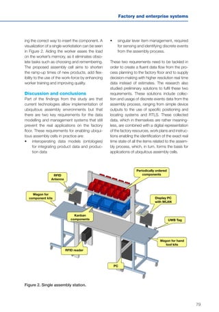
![80
Exploitation potential
In a knowledge management sense, the ubiq-
uitous manufacturing concept can yield high
gains when correctly implemented. Although
the implementation can be seen as very heavy
and thorough, it should be possible to test it
out by implementing it only partially in selected
areas and using it only as an analytic applica-
tion instead of an operative one. The operative
planning applications can also be used with
the addition of existing systems and human
expertise to verify planning.
As ubiquitous manufacturing makes pro-
duction more controllable and accurate in the
sense of orders, it enhances the ability to fulfil
orders, including specific ones by customers.
Controllable production also makes it easier
for the plant to adapt to changes in the event
of reconfiguration and in the sense that it can
ease the need for buffer stocks, reducing the
amount of work in progress (WIP).
References
[1] Haller, S., Karnouskos, S. & Schroth, C. The
Internet of Things in an Enterprise Context.
Future Internet – FIS 2008, First Future
Internet Symposium, revised selected
papers. Springer-Verlag, 2008. 15 p.
[2] Subirana, B., Sarma, S., Fleisch, E. 2006.
High-Resolution Management. IESE Alumni
Magazine, July/September, 2006, pp. 8–13.
[3] Lucke, D. & Constantinescu, C. Smart
Factory Data Model: Foundation of Con-
text-Aware Applications for Manufacturing.
7th International Conference on Intelligent
Computation in Manufacturing Engineer-
ing, CIRP ICME ’10, 23–25 June, 2010. 4 p.](https://image.slidesharecdn.com/vttresearchhighlights3fgfissuuversio-140319040805-phpapp02/85/Production-matters-VTT-in-global-trends-80-320.jpg)
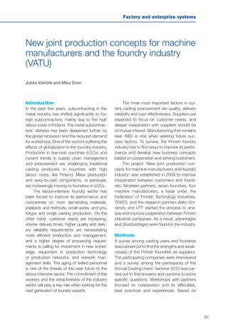
![84
Manual work support throughout the
system life cycle by exploiting Virtual and
Augmented Reality (ManuVAR)
Boris Krassi
Introduction
ManuVAR is an EU research and development
project [1, 2]. It focuses on the high value of
high-knowledge manual work that cannot be
offshored or automated because it constitutes
the core of the business operation. It has to be
made locally and manually with highly expe-
rienced and knowledgeable personnel. The
success of the business relies on the knowl-
edge and skills of the personnel rather than on
minimizing labour costs.
The project aims to develop new tech-
nology and methods to improve manual work
across five industry domains: terrestrial satel-
lite assembly, design of assembly lines in small
enterprises, maintenance in the railway sec-
tor, training in non-destructive techniques in
power plant maintenance, and heavy machin-
ery productization and maintenance.
Methods
ManuVAR combines several disciplines:
• Product life cycle management (PLM)
• Virtual and augmented reality technolo-
gies (VR/AR)
• Ergonomics methods and knowledge
management.
The project workflow includes the following
stages:
• identify the most common problem areas
regarding manual work across industries
• design and implement a set of tools and
methods to address these problem areas
• test the tools and methods in the labora-
tory and on the factory floor.
Results
ManuVAR has identified seven key problem
areas regarding high knowledge, high-value
manual work that is common to all five indus-
try areas [2]:
1. problems with communication throughout
the life cycle
2. poor interfaces to complex information
systems
3. an inflexible design process in terms of
adaptation to system customization and
changes
4. inefficient knowledge management
5. low productivity
6. lack of technology acceptance of VR/AR
technology
7. physical and cognitive stress.
To respond to these problem areas, the following
three groups of results have been developed:
1. Technological: the platform of modu-
lar reconfigurable VR/AR tools; system
architecture based on the ‘virtual model’;
and tested technical prototypes [5, 11].
2. Methodological: the key problem areas
regarding manual work; the Manu-
VAR PLM model and its application
methodology; the framework of ergo-
nomics methods to support manual work
throughout the system life cycle; training
and implementation support methodol-
ogy; and the knowledge management
concept [4, 10].
3. Policy: recommendations and evidence
for policymakers (industry, community,
political) that high knowledge, high-value](https://image.slidesharecdn.com/vttresearchhighlights3fgfissuuversio-140319040805-phpapp02/85/Production-matters-VTT-in-global-trends-84-320.jpg)
![85
Factory and enterprise systems
manual work can be an opportunity for
European industries.
The main characteristics of the ManuVAR sys-
tem architecture include (Figure 1):
• Bi-directional communication through-
out the system life cycle (e.g. workers’
feedback to the designers, the design-
ers’ recommendations to the workers)
is accomplished by means of a ‘virtual
model’. The virtual model plays the role of
a communication mediator – a single sys-
temic access point to the variety of data,
information, models on the system for all
users in the life cycle – accessed as an
integral system by ‘virtual experiments’ [5].
• Adaptive VR/AR user interfaces to the
complex virtual model that fits all actors
in the life cycle from workers to engineers
and managers. The VR/AR interfaces are
implemented through component reconfig-
uration with low-delay middleware (haptics,
tracking, VR/AR visualization, application
logic, connection to PLM systems) [3].
Figure 1. The ManuVAR PLM model and the concept of bi-directional communication
through the life cycle. Several actors (a worker, a designer and a human factors expert)
located at different stages of the life cycle (outer layer) communicate off-line or on-line
with each other via the virtual model (in the centre). Each actor has a customized view
(user interface) of the shared virtual model. As soon as one actor affects the virtual
model, all other actors are able to perceive the result. Compared with the process-driven
communication in a chain, this communication is more flexible and allows easier change
management and synchronization among multiple actors. Source: [5]](https://image.slidesharecdn.com/vttresearchhighlights3fgfissuuversio-140319040805-phpapp02/85/Production-matters-VTT-in-global-trends-85-320.jpg)
![86
• Four groups of human factor methods
to cluster the principal ways to improve
manual work from the system-cybernet-
ics perspective [4]: workplace design,
ergonomics evaluation, instruction deliv-
ery and training.
• The knowledge management con-
cept based on Nonaka’s organizational
knowledge creation theory [12] with each
modality of knowledge creation sup-
ported: externalization and internalization
(adaptive and natural user interfaces with
VR/AR), socialization (bi-directional com-
munication and the virtual model) and
combination (linking in the virtual model
and connection to PLM systems).
The project has implemented four reconfigur-
able application tools that can be combined
Figure 2. An example of the combined ManuVAR tool – participatory cross-disciplinary
design review of a new product. Several experts – engineers, workers and managers – inves-
tigate a shared virtual environment view of the product (assembly sequence, ergonomics
issues) before it is brought into production to find possible design faults. Source: [13]
via the virtual model to solve a given industrial
case (Figure 2):
• Contextual instruction delivery: AR, track-
ing; remote and local versions [7]
• Ergonomics evaluation: automatic physi-
cal and cognitive load analysis, full body
motion capture [6]
• Task analysis and procedure validation:
hierarchical task analysis tool, VR with
haptics [8]
• Motor skill training: VR with haptics, preci-
sion-teaching theory [9].
Conclusions
Offshoring is a natural phenomenon. It will exist
while there are big differences in labour costs,
but European industries could turn their atten-
tion to business that cannot be offshored, e.g.
unique or deeply customized products, main-](https://image.slidesharecdn.com/vttresearchhighlights3fgfissuuversio-140319040805-phpapp02/85/Production-matters-VTT-in-global-trends-86-320.jpg)
![87
Factory and enterprise systems
tenance of fixed installations, and operation
and maintenance of machinery. This business
is an opportunity for Europe because it relies
on the knowledge and skills of people rather
than on minimizing labour costs. ManuVAR has
developed methods and tools for bi-directional
communication and knowledge management
for all actors in the life cycle, adaptive user inter-
faces with AR/VR, and application tools based
on ergonomic methods improving high knowl-
edge, high-value manual work.
Acknowledgements
The results presented in this paper are the
outcome of the joint efforts of the ManuVAR
Consortium. The research leading to these
results has received funding from the European
Commission’s Seventh Framework Programme
FP7/2007–2013 under grant agreement
211548 ‘ManuVAR’.
References
[1] ManuVAR website: http://www.manuvar.eu.
[2] Krassi, B., D’Cruz, M. & Vink, P. Manu-
VAR: a framework for improving manual
work through virtual and augmented real-
ity. Proceedings of the 3rd International
Conference on Applied Human Factors
and Ergonomics, AHFE2010, Miami, FL,
USA, 17–20 July, 2010. Published in:
Vink, P., Kantola, J. (eds.). Advances in
Occupational, Social, and Organizational
Ergonomics. CRC Press, 2010.
[3] Krassi, B., Kiviranta, S., Liston, P., Leino,
S.-P., Strauchmann, M., Reyes-Lecuona,
A., Viitaniemi, J., Sääski, J., Aromaa, S. &
Helin, K. ManuVAR PLM model, method-
ology, architecture, and tools for manual
work support throughout system lifecycle.
[4] Aromaa, S., Viitaniemi, J., Leva, C. &
Krassi, B. Integration of Human Factors
methods to the ManuVAR Product Lifecy-
cle Management model.
[5] Krassi, B., Strauchmann, M., Kiviranta, S.,
Leino, S.-P., Viitaniemi, J., Reyes-Lecuona,
A. & Sääski, J. Virtual Model for Supporting
Communication of Manual Work Information
Throughout System Lifecycle. Fraunhofer
Institute for Factory Operation and Automa-
tion (IFF) days 2010, Magdeburg, Germany,
15–17 June, 2010. Pp. 228–233. Full text:
www.vtt.fi/inf/julkaisut/muut/2010/Krassi_
et_al.pdf.
[6] van Rhijn, G., Bosch, T. & de Looze, M.
Mixed Reality System and objective ergo-
nomics evaluation for designing work
stations in manufacturing industry. Joint
VR Conference of euroVR and EGVE, Not-
tingham, UK, 2011. http://www.vtt.fi/inf/
pdf/symposiums/2011/S269.pdf
[7] Azpiazu, J., Siltanen, S., Multanen, P.,
Mäkiranta, A., Barrena, N., Díez, A., Agirre, J.,
Smith, T. Remote support for maintenance
tasks by the use of Augmented Reality: the
ManuVAR project // ibid.
[8] Gaia, E., Basso, V., Vizzi, C., Virtual Reality
for planning and validating spacecraft inte-
grating procedures in Thales Alenia Space
Italia // ibid.
[9] Poyade, M., Reyes-Lecuona, A., Frutos, E.,
Flores, S., Langley, A., D’Cruz, M., Valdina,
A., Tosolin, F. Using virtual reality for the
training of the Metallographic Replica
technique used to inspect power plants by
TECNATOM S.A. // ibid.
[10] Liston, P., Kay, A., Cromie, S., Leva, C.,
D’Cruz, M., Patel, H., Langley, A., Sharp-
les, S., Aromaa, S. Evaluating the iterative
development of VR/AR human factors tools
for manual work. 18th World Congress of
Ergonomics, 2012.
[11] Leino, S-P., Pulkkinen, A. Design for
Human-Virtual Engineering is a Media for](https://image.slidesharecdn.com/vttresearchhighlights3fgfissuuversio-140319040805-phpapp02/85/Production-matters-VTT-in-global-trends-87-320.jpg)
![88
Knowledge Transfer. International Design
Conference, DESIGN2012, Dubrovnik,
Croatia, 21–24 May, 2012.
[12] Nonaka, I., Takeuchi, H.A. Dynamic Theory
of Organisational Knowledge Creation.
Organisational Sciences, Vol. 5, Iss. 1,
1994, pp. 14–37.
[13] Heikkilä, J., Helin, K. & Leino, S.-P. Cus-
tomer Requirements Validation with VR
Technologie – Case Metso Minerals. In:
Helin, K. & D’Cruz, M. (eds.). VR Confer-
ence of euroVR and EGVE. Current and
Future Perspectives of Virtual Reality,
Augmented Reality and Mixed Reality:
Industrial and Poster Track, Nottingham,
UK, 20–21 September, 2011. http://www.
vtt.fi/inf/pdf/symposiums/2011/S269.pdf.](https://image.slidesharecdn.com/vttresearchhighlights3fgfissuuversio-140319040805-phpapp02/85/Production-matters-VTT-in-global-trends-88-320.jpg)

![90
Strategic development of enterprise
networks (Verka)
Katri Valkokari
Introduction
The rules of the game have changed dra-
matically in the past 15 years. The ability to
build up effective and mutually beneficial part-
nerships and networks is the foundation of
current business success. The key success
factors of networks are the willingness and
ability of companies to participate in them and
the ability to use future business opportunities
together with other companies entering the
networks and business alliances. The com-
pany’s own strategic decisions on networks
(which networks to enter and why, in which
role and with whom) should form the basis of
network development.
The scope of the Verka project was the
research of the network’s growth and devel-
opment dynamics. The aim was to configure
new network development methods based on
the theoretical background and the compa-
ny’s needs defined in eight Finnish technology
industry case networks.
A need for new strategic network devel-
opment methods was recognized, e.g. how
to analyse a company’s network relations in
complex dynamic networks and how to find
optimal partners and a common network strat-
egy. There is a need to find ways to enhance
the competitiveness of networks and organize
long-term multilateral cooperation and devel-
opment work in an effective way.
The Verka tools can be divided in two
groups: 1) tools to describe the network envi-
ronment and choose suitable partners to start
the cooperation, and 2) tools to create the net-
work strategy and agree on the ground rules
of the cooperation.
Methods
The Verka toolbox for strategic network
development is constructed based on previ-
ous network development cases in which
researchers from the VTT Business and Tech-
nology Management Knowledge Centre have
participated. The core companies in the pre-
vious case networks were HT Lasertekniikka
Oy, Juha Lemponen Oy, Maaseudun Kone Oy
and Nautor Oy, Reikälevy Oy ja Verkko A ry.
The structures of the networks, network
life cycle phases, methods used and devel-
opment themes of the case-networks were
analysed. As a result, a new network life cycle
model was developed and the needs for new
network development methods were defined.
The tools were further developed and
tested in three cases during the Verka project.
Nekos (formerly Nekomat belos), Purso Tools
and Arla-Ingman took part in the testing and
development of the tools. The development
work and the cases were presented in [1]. The
Verka tools were also published in the working
book and on the web pages (www.verka.fi).
Results
The toolbox for strategic network development is
tailored for network developers. It offers tools to:
• identify the company’s network portfolio
and partnerships
• shape an optimal network structure and
joint vision](https://image.slidesharecdn.com/vttresearchhighlights3fgfissuuversio-140319040805-phpapp02/85/Production-matters-VTT-in-global-trends-90-320.jpg)
![92
Exploitation potential
The Verka toolbox is suited to strategic analy-
ses and development of different kinds of
business and development networks. It can
broadly be used in innovation, R&D, produc-
tion, sales and marketing networks in different
branches and at different levels of networks.
The systematic development work sup-
ported by the toolbox enables the creation of
the network’s joint interests and shared inten-
tion. The tools support collaborative develop-
ment work between the network partners.
Acknowledgements
The Verka project was mainly funded by Tykes,
the workplace development programme of the
Finnish Ministry of Labour. The representatives
of the Tykes Program and the steering group of
the Verka project also supported the develop-
ment work with their valuable comments. The
researchers would like to thank all the repre-
sentatives of the participating networks: their
willingness to engage in open but challenging
discussions was a prerequisite of the develop-
ment work. The author also wishes to thank the
Verka researcher group and other colleagues
involved for their contribution to this work.
Publications
Hyötyläinen, R., Anttila, J.-P., Hakanen, T.,
Kalliokoski, P., Poikkimäki, J., Valjakka, T. &
Valkokari, K. PARTNET – Kehittyminen järjes-
telmätoimittajana. Tykes julkaisut, raportti 43.
Helsinki, 2005. http://www.tekes.fi/ohjelmat/
Tyke/Aineistot/Tykes+-ohjelman+raportit.
Valkokari, K., Kulmala H.I. & Ruohomäki I. Toi-
mittajaverkoston johtamisen työkalut – Case
Ruukin Kattoasennuspalvelun verkoston kehit-
täminen. Tykes julkaisut, raportti 44. Helsinki,
2006. http://www.tekes.fi/ohjelmat/Tyke/Aine-
istot/Tykes+-ohjelman+raportit.
Verkoston strategisen kehittämisen työkirja &
Verka tool box (Menetelmiä verkostojen kehit-
tämiseen). http://www.vtt.fi/proj/verka/index.
jsp. (In Finnish.)
References
[1] Valkokari, K., Hakanen, T., Airola, M. Yrity-
sverkoston strateginen kehittäminen. VTT
Research Notes 2348. VTT, Espoo, Finland,
2006. http://www.vtt.fi/inf/pdf/tiedot-
teet/2006/T2348.pdf.](https://image.slidesharecdn.com/vttresearchhighlights3fgfissuuversio-140319040805-phpapp02/85/Production-matters-VTT-in-global-trends-92-320.jpg)
![97
Enterprise networks
Virtual organization management
(ECOLEAD)
Martin Ollus and Iris Karvonen
Introduction
Today, the competitive environment in manu-
facturing and service industries is forcing
these industries to change their operations.
To be successful in a very competitive and
rapidly changing environment, significantly
improved competencies are needed. Small
and medium-sized organizations, in par-
ticular, participate in networks to achieve
a differentiated competitive advantage. By
collaborating, they can rapidly respond to
market demands by sharing competencies
and resources. The new forms of operation
affect business models, strategies, organiza-
tional and governance principles, processes
and technological capabilities. Companies
are increasingly restructuring their internal
operating and information systems and re-
engineering production processes to eliminate
waste and lower costs. New organizational
forms naturally emerge supported by col-
laborative tools based on the Internet, mobile
computing and a better understanding of the
mechanisms of collaborative networks [1].
There is growing awareness that the col-
laboration in networks has a multidisciplinary
nature based on information and communica-
tion technologies, socio-economics, opera-
tions research, organizational business man-
agement, and legal, social security and ethical
areas, among others. The European project
ECOLEAD (European Leadership Initiative in
Collaborative Network Organisations, 2004–
2008) was launched to create the neces-
sary strong foundations and mechanisms for
establishing an advanced collaborative and
network-based industry society, taking a holis-
tic view on concepts, methods and tools for
collaborative networked organizations.
As part of ECOLEAD, the Management
of Virtual Organizations (VO) was studied.
A Virtual Organization is defined as a set of
col-laborating independent organizations,
which, to the outside world, provide services
and functionality as if they were one organiza-
tion, supported by computer networks [2]. A
VO is created within a collaboration network,
called a Virtual Organization Breeding Environ-
ment (VBE). The VO is usually formed to create
value for a customer [3]. It is a temporary con-
sortium and is dissolved after the delivery of
its product/service. Its duration may vary from
very short-term tasks (hours or days) to exten-
sive deliveries (years). New VOs can be formed
for new emerging needs. The composition of
the VO may vary even for similar tasks.
When a VO is closed, the possible contin-
uation of similar tasks is not necessarily known
and the dissolution phase ends the concrete
collaboration. Actions to maintain the experi-
ence and collaboration potential are essential
in this phase.
VO management
The main challenges for VO management
(VOM) come from the temporary nature and
distribution of operations in independent or-
ganizations with their own aims, behaviour
and culture. VOM is defined to contain the
organization, allocation and coordination of
resources and their activities as well as their
inter-organizational dependencies to achieve](https://image.slidesharecdn.com/vttresearchhighlights3fgfissuuversio-140319040805-phpapp02/85/Production-matters-VTT-in-global-trends-97-320.jpg)
![98
the objectives of the VO within the required
time, cost and quality frame [4]. It cannot nec-
essarily be managed like a single organization.
In ECOLEAD, a concept of ‘Real time
VO management’ was used for the develop-
ment of e-services to support the VO manag-
er’s decision-making [5]. The management of
collaboration requires continuous awareness
of the state of the activities and tools for the
implementation of the necessary actions. In
most tasks, the managers are interested in
the main status information, as in shown in
Figure 1.
The necessary interventions have to be
implemented taking into account the specific
features of each VO, like the type of its objec-
tives, its preparedness level, the risk involved
in the objectives and the level of dependencies
between the partners and tasks [4].
“Are we earning
or wasting money?”
“Are we in line
with our plan?”
“What (where) is the reason
for the problem?”
Finance
Monitor
Activities
Monitor
Operations & Performance
Monitor
Figure 1. Management and monitoring activities.
The developed management support con-
tained a dashboard helping the VO manager(s)
to define the necessary interventions. The dash-
board is illustrated in Figure 2.
A distributed monitoring and management
support system was developed and tested in a
distributed environment with VO partners in sev-
eral European countries.
VO inheritance
By definition, the VO is a temporary activity.
Its disclosure may lead to a risk of losses of
information, knowledge or other values. To
reduce this risk, an activity called VO inher-
itance was developed. It is defined as ‘the
practice of storing and forwarding experi-
ences and other non-proprietary assets
created through collaboration in a VO’ [6].
The aim is to strengthen the Network or VBE](https://image.slidesharecdn.com/vttresearchhighlights3fgfissuuversio-140319040805-phpapp02/85/Production-matters-VTT-in-global-trends-98-320.jpg)
![99
Enterprise networks
Figure 2. Management dashboard.
by preserving common valuable outcomes
(‘VO heritage’). When the VO is dissolved,
useful outcomes should be returned, ‘inher-
ited’ by the VBE. In addition to the individual
benefits for the VO members, the inherited
assets can be used to improve the prepar-
edness of the VBE. Furthermore, references
and the reputation created by successful VOs
can be used as promotional information for
customers. Currently, most operating net-
works do not have systematic management
of VO inheritance.
In ECOLEAD, components of VO inher-
itance were identified and inheritance pro-
cesses, methods and mechanisms studied.
In addition to intellectual inheritance, there
are also other types of inheritance, such as
financial and relational or social inheritance
that need to be considered [7].
Conclusions
The preparedness of the network (VBE) impacts
significantly on the success of VO management
and VO inheritance. The VOs should be created
fast. Consequently, VO management practices
and principles should be prepared in advance
within the VBE. The VO inheritance can be seen
as an enabling activity for continuous improve-
ment in the VBE using the experience gained in
dissolved VOs.
In network collaboration, decisions are
made in a decentralized manner. The intangi-
ble assets and collaboration ability have to be
emphasized, although most coordination activi-
ties focus on the achievement of measurable
aims and necessary management interven-
tions, and actions focus on the enhancement of
collaboration performance. This area seems to
be an important issue for further development.](https://image.slidesharecdn.com/vttresearchhighlights3fgfissuuversio-140319040805-phpapp02/85/Production-matters-VTT-in-global-trends-99-320.jpg)
![100
References
[1] Camarinha-Matos, L.M., Afsarmanesh,
H. 2006. Collaborative networks: Value
creation in a knowledge society. (Invited
keynote paper). In: Proceedings of PROLA-
MAT 2006, IFIP Int. Conf. On Knowledge
Enterprise – New Challenges, Shanghai,
China, Jun 2006, Springer.
[2] Camarinha-Matos, L.M., Afsarmanesh H.,
Ollus M. (eds.). 2008. Methods and tools
for collaborative networked organizations.
New York: Springer, ISBN: 978-0-387-
79423-5.
[4] Karvonen, I., Salkari, I., Ollus, M. 2005.
Characterizing virtual organization and
their management. In: Camarinha-Matos,
L., Afsarmanesh, H. & Ortiz, A. (ed.). Col-
laborative Networks and Their Breeding
Environment. Springer. Pp. 193–204.
[5] Negretto, U., Hodik, J., Kral, L., Mulder, W.,
Ollus, M., Pondrelli, L., Westphal, I. 2008. VO
Management Solutions. VO Management
e-Services. In: Camarinha-Matos, L.M.,
Afsarmanesh H., Ollus, M. (Eds.) Methods
and Tools for Collaborative Networked
Organizations, New York: Springer. ISBN
978-0-387-79423-5.
[6] Karvonen, I., Salkari, I., Ollus, M. 2007.
Identification of forms and components of
VO inheritance. In: IFIP International Fed-
eration for Information Processing. Volume
243, Establishing the Foundation of Col-
laborative Networks. Camarinha-Matos, L.,
Afsarmanesh, H., Novais, P., Analide, C.,
(eds.). Boston, Springer. Pp 253–262.
[7] Karvonen, I., Salkari, I., Ollus, M. 2010.
Increasing collaboration preparedness and
performance through VO inheritance. Inter-
national Journal of Services and Operations
Management (IJSOM), Special Issue on
Modelling and Management of Knowledge
in Collaborative Networks. Vol. 6, No. 3, pp.
293–312.
[3] Kürümlüoglu, M., Nostdal, R., Karvonen,
I. Base concepts. 2005. In: Virtual
organizations. Systems and practices.
Camarinha-Matos, L.M., Afsarmanesh, H.,
Ollus, M. (eds.). Springer. Pp. 11–28.](https://image.slidesharecdn.com/vttresearchhighlights3fgfissuuversio-140319040805-phpapp02/85/Production-matters-VTT-in-global-trends-100-320.jpg)
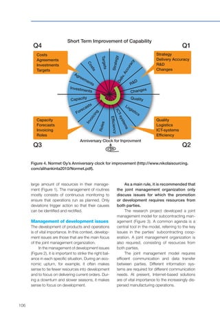
![110
Developing the strategic innovation
capabilities of enterprises (InnoPro)
Tapio Koivisto
Introduction
Innovation and innovativeness are key to
economic vitality. Given the new competitive
conditions in the global economy, innovation
is a crucial factor that affects the ability of firms
to adapt to new constraints, take advantage
of new business opportunities and create new
business concepts. It also contributes signifi-
cantly to company growth.
Innovation can take many forms. The
argument for strategic innovation is voiced
by a number of academics and consultants
(see e.g. [1, 2, 3]). Strategic innovation can
occur when a company identifies gaps in the
industry positioning map and decides to fill
them [4]. Gaps refer to: 1) new, emerging cus-
tomer segments that other competitors have
neglected; 2) new, emerging customer needs
or existing customer needs not served well by
other competitors; and 3) new ways of pro-
ducing, delivering or distributing existing or
new products or services to existing or new
customer segments. Gaps appear for a num-
ber of reasons, such as changing consumer
tastes and preferences, changing technolo-
gies, changing policies, etc. Gaps can be cre-
ated by external changes or proactively by the
company.
Purposes of the project
This paper is based on the project named
‘Innovation Capability of Enterprises – InnoPro’.
The project was implemented by the Strategic
Innovations team of VTT Industrial System. The
purpose of the InnoPro project was to develop a
workable approach and method of intervention
for developing the innovation capability of SMEs.
A central issue was to develop an enterprise-
and futures-oriented approach and method,
considering the fact that firms are essentially
heterogeneous [5]. Since firms are heterogene-
ous, there is no single correct model, method or
‘best practice’ for strategizing innovation. From
the point of view of the enterprises, it is also
essential to bear in mind that innovation involves
a fundamental element of complexity and uncer-
tainty (see e.g. [6]).
Most prescriptive text on strategic plan-
ning presumes that triggering change is simply
a matter of environmental scanning and analy-
sis and then paying heed to the often subtle
signals of significant threats or opportunities.
However, this view ignores the fact that mem-
bers of social practices interact not with an
objectively given environment but rather with
perceptions of the ‘environment’. They act the
way they do because they think the way they
do, and they think the way they do because
they act the way they do.
The method of strategy sounding
The concrete strategy and method of inter-
vention of our project is based on Jan-Peter
Vos’s [7, 8, 9] analysis of strategy making. The
method of strategy sounding was developed
to support identification, selection and reten-
tion of strategic opportunities.
The method of strategy sounding links
together the six important strategic choices of
an enterprise: the business choice, the vision
choice, the tactics choice, the competence
choice, the asset choice and the performance](https://image.slidesharecdn.com/vttresearchhighlights3fgfissuuversio-140319040805-phpapp02/85/Production-matters-VTT-in-global-trends-110-320.jpg)
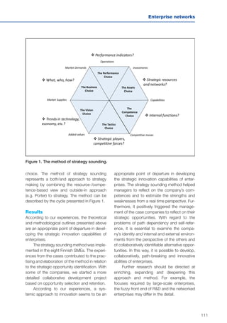
![112
References
[1] Hamel, G. & Prahalad, C.K. Competing for
the Future. Harvard Business School Press,
Boston, MA, USA, 1994.
[2] Drucker, P.F. The discipline of innovation.
Harvard Business Review, 76(6), 1998,
pp. 149–157.
[3] Styles, C. & Seymour, R. 2004. Creativity and
Strategic Innovation. Proceedings of the
ANZMAC 2004 Conference, Wellington, New
Zealand, 29 November – 1 December, 2004.
[4] Markides, C. Strategic innovation. In: E.B.
Roberts (ed.). Innovation. Driving Product,
Process, and Market Change. Jossey-Bass,
San Francisco, CA, USA, 2002. Pp. 9–40.
[5] Penrose, E. The Theory of the Growth of
the Firm. Basil Blackwell, Oxford, UK, 1959.
[6] Dosi, G. The nature of innovative process.
In: Dosi, G., Freeman, C., Nelson, R., Silver-
berg G. & Soete L. (eds.). Technical Change
and Economic Theory. Pinter Publishers,
London & New York, 1988. Pp. 221–238.
[7] Vos, J.-P. The making of strategic realities:
An application of the social systems theory
of Niklas Luhmann. Eindhoven University
Press, Holland, 2002.
[8] Vos, J.-P. Developing strategic self-
descriptions of SMEs. Technovation, 25,
2005, pp. 989–999.
[9] Vos, J.-P. Strategic Management from a Sys-
tems-Theoretical Perspective. In: Seidl, D.
& Becker K.H. (eds.). Niklas Luhmann and
Organization Studies. Kristianstad: Liber &
Copenhagen Business School Press, Den-
mark, 2005. Pp. 365–385.](https://image.slidesharecdn.com/vttresearchhighlights3fgfissuuversio-140319040805-phpapp02/85/Production-matters-VTT-in-global-trends-112-320.jpg)
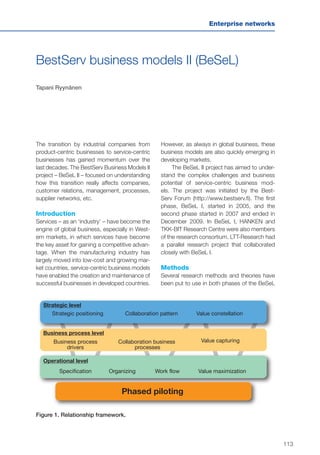
![114
project, e.g. value creation and capture, eco-
nomic modelling, process and system theories,
innovation theories, service classification (e.g.
SPA matrix), relationship marketing, service
management and knowledge management.
Research material has been collected by
means of interviews and collaborative group
work. Qualitative analysis has then been
applied.
Results
Several methods and tools have been devel-
oped. They have been published in research
papers, seminar papers and publications. One
example of a model from BeSeL I is a rela-
tionship framework that pinpoints the most
important topics that should be focused on in
customer relationships when developing new
industrial services (Figure 1).
Conclusions
Over this four-year period, it has become quite
clear that although many companies have
decided to opt for service-centric business
models, practical implementation and real oper-
ational changes take time. The service business
requires systemic innovations and an iterative
learning process, not only within a company but
also across the business network.
The service business approach makes it
possible for a company to pursue new reve-
nue streams and customer segments by deliv-
ering total solutions. Value creation through
service-based customerships provides a
competitive edge that many system suppliers
in particular need when a low-cost strategy
leads companies to move their business into
areas specializing in manufacturing or close to
the end customer.
Exploitation
Dissemination allows industry to benefit from
the BeSeL results. Several articles and semi-
nar papers have been published. A book on
the topic was published by Teknova: ‘From
Industrial Favours to Industrial Services – Prof-
itable Growth as a Challenge’ [1].
Acknowledgements
We would like to acknowledge the partici-
pating companies TEKES and VTT Technical
Research Centre of Finland for funding, par-
ticipating in and supporting this work. The
companies participating in the BeSeL I or the
Besel II project are Vaisala Oyj, M-real Oyj,
Fastems Oy, Onninen Oy, Lappset Group Oy,
Hydnum Oy, Wärtsilä Oyj, Oy International
Business Machines Ab (IBM), Altia 1888 and
Nordea Markets Finland.
Key Researchers
Tapani Ryynänen, Iiro Salkari, Heidi Korhonen,
Jari Kettunen, Raimo Hyötyläinen and Henri
Hytönen from VTT, and Christian Grönroos,
Pekka Helle and Robert Wendelin from Hanken
Publications
de Brentani, U. Innovative versus incremental
new business services: Different keys for achiev-
ing success. The Journal of Product Innovation
Management, 18, 2001, pp. 169–187.
Grönroos, C. & Helle, P. Adopting a service
logic in manufacturing: conceptual foundation
and metrics for mutual value creation. Journal
of Service Management, Vol. 21, No. 5, 2010,
pp. 564–590.](https://image.slidesharecdn.com/vttresearchhighlights3fgfissuuversio-140319040805-phpapp02/85/Production-matters-VTT-in-global-trends-114-320.jpg)
![115
Enterprise networks
Helle, P. Re-conceptualizing value creation:
from industrial business logic to service busi-
ness logic, working paper, Hanken School of
Economics Finland, 2010.
Helle, P. Towards understanding value crea-
tion from the point of view of service provision,
conference report, EIASM Marketing Forum,
Capri, 2009.
Hytönen, H., Jarimo, T. & Salkari, I. A model for
value-based pricing of industrial services, 2nd
POMS College of Service Operations Confer-
ence, Carmel, CA, USA, 2–3 June, 2006.
Korhonen, H., Piispa, T. & Salkari, Iiro. Organi-
zational Challenges for a Supplier of Physical
Goods Turning Service Provider. 6th Interna-
tional Conference on Knowledge, Culture and
Change in Organizations, Prato, Italy, 2006.
Korhonen, T. Arvomallin soveltaminen palve-
luliiketoiminnan kehittämisessä. (Using Value
Model in Industrial Service Development.)
Master’s thesis. BeSel project, Helsinki Uni-
versity of Technology, BIT Research Centre,
Espoo, 2010. (In Finnish.)
Lehtiö, T. & Nopanen, E. Aineeton potentiaali
palvelukokonaisuudessa, Mittausmenetelmiä
ja tunnuslukuja. Helsinki University of Tech-
nology, BIT Research Centre, Report Series
2009/2, Espoo, Finland, 2009. (In Finnish.)
Ryynänen, T. Survival challenges of an in-
house service innovation in traditional industrial
context. Proceedings of the 2nd ISPIM Inno-
vation Symposium, New York City, NY, USA,
6–9 December, 2009.
Ryynänen, T. & Malinen, P. Using Decision
Point framework to analyse evolutionary steps
in industrial service business. IFKAD Forum,
2008.
Ryynänen, T. & Salkari, I. A Systemic Meth-
odology for Facilitating Service Innovations.
ERIMA Conference, 2007.
Salkari, I. & Ryynänen, T. Getting a Grip of
Customer Value Creation in Developing Indus-
trial Services. ERIMA Conference, 2008.
References
[1] Grönroos, C., Helle, P., Tinnilä, M., Hyö-
tyläinen, R., Apilo, T., Korhonen, H.,
Malinen, P., Piispa, T., Ryynänen, T. &
Salkari, I. Teollisuuden palveluksista
palveluliiketoimintaan – haasteena kan-
nattava kasvu. (From Industrial Favours to
Industrial Services – Profitable Growth as
a Challenge.) Teknologiainfo Teknova, Hel-
sinki, Finland, 2007. (In Finnish.)](https://image.slidesharecdn.com/vttresearchhighlights3fgfissuuversio-140319040805-phpapp02/85/Production-matters-VTT-in-global-trends-115-320.jpg)
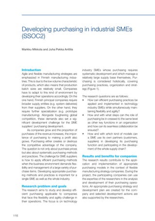
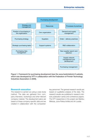


The document discusses the challenges facing the European manufacturing industry, particularly the shift of production to low-wage countries and the necessity for innovative production methods to remain competitive. It emphasizes the importance of developing specialized production capabilities that leverage unique skills rather than relying solely on low labor costs, while advocating for the integration of digital and additive manufacturing technologies. The report presents various research projects aimed at enhancing manufacturing processes through flexible production systems and augmented reality applications, revealing significant potential for productivity improvements.


