
Recommended
More Related Content
What's hot
What's hot (20)
Similar to Varnish.pptx
Similar to Varnish.pptx (20)
Recently uploaded
Recently uploaded (20)
Varnish.pptx
- 1. Varnish
- 2. • Varnish is a soft contaminant composed of lubricant degradation by-products that are less than 1 micron in size and is not measured by traditional particle count • Varnish deposit is a thin-orange, brown or black insoluble film deposit occurring on internal of lubricant systems • Varnish is a high molecular weight substance that is unstable in oil • Varnish deposit is unable to remove by mechanical filtration What is Varnish? Varnish is a hard, lacquer-like oil-insoluble substance that is difficult to remove—great for wood, not so much for machinery.
- 3. • Sludge is varnish which have higher water content • Sludge look like a soft mud-like deposit that settles out of the oil • Sludge is also a soft contaminant • Sludge contaminant, if prolonged elevated temperatures will evaporate the moisture from the sludge contaminant What is Sludge? Sludge—often a varnish precursor—is a soft, pliable residue that’s less tenacious.
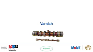
- 4. • Sticking or sized occurs in moving mechanical parts such as servo control valve • Plugged or restricted small oil flow orifices • Loss of heat conversion efficiency in heat exchangers due to varnish’s insulation effect • Attract dirt and larger contaminants, increasing wears and component failure • Encourage premature bearing failure • Catalytic deterioration of turbine oils ( and hydraulic oils) • Increased maintenance costs due to cleanup and disposal of oil Potential Problems caused by Varnish Spool and Bore
- 5. Varnish Formation Thermal degradation Thermal degradation happens at temperatures above 299 C and leads to oxidation. There are four potential sources of heat: i. Full spark discharge ii. Dark stream spark discharge iii. Friction iv. Adiabatic compression
- 6. Varnish Formation Contamination Although contaminants come from a variety of sources, internal contamination is most often submicron oxidized oil that agglomerates to leave deposits. Certain oil additives can create more varnish than others—including some rust inhibitors. These contaminants agglomerate into sludge and varnish. Oxidation Oxidation is accelerated by exposure to temperatures of 249 C and above. Elevated temperatures accelerate the oxidation process; for every 10 C increase in operating temperature, the rate of oxidation doubles. The present of aeration, water and metals accelerates oxidation. Once underway, oxidation by- products develop into insoluble contaminants.
- 7. Electrostatic Discharge (ESD) ESD is produced by friction that results when two surfaces move in relation to each other—this usually means they must come in contact with each other, but not always. Common causes of electrostatic charge in a system include one or more of the following: • Fluid flowing through narrow passages • Fluids passing through filters • Fluids that travel through systems at high speeds and/or are highly agitated • Fluids that are kept at lower temperatures • Fluids that become aerated. ESD leads to the formation of free radicals within the oil, which leads to uncontrolled polymerization that culminates in the buildup of insolubles like varnish and sludge
- 8. Filtration and static The transition to synthetic and glass filters with tighter pores coupled with higher filter flow rates has created a perfect storm for ESD. A high flow rate creates high voltages that result in more powerful and frequent spark discharges. If the filter is made of nonconductive materials like these, the charge will not be able to dissipate into the filtration system. Then the filter will charge until the voltage reaches a certain point and discharge to conductive parts such as the metal components of the filter housing—causing significant damage. While grounding the filter system will prevent sparking, it will not prevent either the filter or fluid passing through it from charging and causing damage.
- 9. How to detect Varnish? Varnish can be vary difficult to detect. Standard oil analysis test may show no signs of varnish when it is present. The best method for detecting varnish is via precision oil analysis (e.g., MobilServ Varnish Analysis). The following are examples where varnish might occur in both gas and steam turbine systems: • Black, curtsy deposits on mechanical seals • Gold adherent films on valves • Charcoal-like deposits on Babbitt sleeve bearings • Gooey-brown accumulations on filters • Black, scabby deposits on mechanical seal surfaces and thrust-bearing pads • Carbonaceous residue on mechanical surfaces
- 10. Factors that Increase Varnish occurrences in Gas Turbines Simplified representation of some of the causes of gas turbine varnish Ref: Practical Approaches to Controlling Sludge and Varnish in Turbine Oils
- 11. Measuring Varnish: Setting removal targets Measurement of varnish potential does not indicate the actual amount of varnish deposited on the surfaces of components It measures varnish precursors in the oil A system can be considered “varnish free” when varnish deposits have disappeared, not necessarily when varnish potential is down. Removal of varnish precursors from the oil displaces the solvency equilibrium in the oil, forcing deposit to “redissolve” in the fluid, then removed by varnish removal units. To be free of varnish, varnish precursor measurements must be consistently low for an extended period. Actual clean up time depends on • Efficiency of varnish precursor removal • Amount of deposits already present in the system • Solvency behavior of varnish in the system (site dependent –machine dependent –oil dependent…)
- 12. Varnish Removal The electrostatic method (EST) Kidney-loop mode, off the main tank Oil is subjected to electrical field causing varnish particles to: • charge / agglomerate to larger particles • captured by filter mat or • attach to charged, disposable surface • As the oil is cleaned up, it lifts varnish deposits into the oil phase, cleaning the surfaces Chemical cleaning/flushing Lube system flushing with chemicals / solvents Softens and removes insoluble materials and the flushing action suspends and helps remove the material by fine filters Several hours to several days System is flushed with appropriate flush fluid to remove residual chemicals Intensive & costly process. Allows quicker removal of deposits. Continuous monitoring and turbine shut down
- 13. Varnish Removal The adsorption method: Utilizes large surface area, high void volume Low fluxes allow proper residence time for adsorption Electro-chemical affinity of the filter media for varnish particles is a KPI
- 14. Prevention Preventing varnish from developing in the first place with a well-balanced formulation of high-performance base stock and advanced additives is a sound strategy. To that end, the following should be considered. • Deposit control. As mentioned earlier, varnish can be generated by thermal degradation, oxidation and contamination. Some oils generate more deposits than others, but advanced turbine oils are formulated to limit the generation of sludge and varnish, while keeping deposits in suspension. • Air release and foam control. Entrained air in oil with inferior air release performance may be compressed in turbine bearings or high-pressure hydraulics, causing adiabatic compression (micro dieseling). Adiabatic compression can cause localized elevated oil temperatures that may promote the formation of varnish. Similarly, excessive surface-level foaming can accelerate oxidation. Oils formulated for rapid air release and minimal foam formation will provide superior protection against varnish. • Filterability. This refers to a fluid’s ability to pass through a filter with minimal pressure drop. Oils with poor filterability will pollute filters faster, which might require more frequent filter changes. • Antirust and corrosion protection. Rust and corrosion contribute to oxidation and the formation of contaminant-based varnish. • Wear protection. Since wear metals act as an oxidation catalyst, wear material from machinery components can lead directly to varnish formation
- 15. The 100% Varnish Prevention Solution According to Fluitec International in Jersey City, N.J., it is possible to prevent all damage from gas turbine lubricant varnish. Following is five-point varnish prevention program: 1. Choose a good oil 2. Monitor oil condition 3. Minimize sparking 4. Maintain the oil 5. Remove contaminants Ref: STLE TLT Magazine
- 16. Turbine Oil System care and Maintenance The Seven steps: 1. Keep the oil clean 2. Keep the oil dry 3. Analyze the oil periodically 4. Ventilation 5. Prevent leakage 6. Maintain Temperature Records 7. Keep operating records Ref: Turbine Oil System Care and Maintenance Mobil Technical Topic
- 17. Suggested Schedule for Oil Analysis of Turbine Systems Taken from ASTM D4378
- 18. Oil Analysis Figure courtesy of Lubrication Engineers, Inc. A better approach is a combination of the following three tests: • Ultracentrifuge, which predicts varnish. • MPC identifies the contamination level in used oil as it relates to oil degradation and potential varnish development. • Remaining useful life evaluation routine (RULER) identifies levels of antioxidants
- 19. Compiled by: Aung Khaing Htun