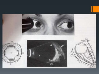
ULTRASOUND METHODS FOR
EVALUATING ORBITAL DISEASES
(By Dr Zain Khatib)
MODERATOR:
Dr Y B Bhajantri
1. BASICS OF ULTRASOUND
2. ORIENTATION AND
EXAMINATION TECHNIQUES
3. ORBIT EVALUATION
PHYSICS
 “ULTRASOUND WAVE” – By definition
Acoustic Wave (Sound wave) + Frequency > 20,000Hz (20KHz)
 Higher the frequency, lower is the wavelength of wave
 In clinical practice – 5 MHz to 50 MHz
High Frequency
Small wavelength
Less Penetration
+
Better Resolution
ABDOMINAL USG OPHTHALMIC USG
Low
frequency
(1 to 5 MHz)
Longer
wavelength
Lower
Resolution
(abdominal
and pelvic
structure)
High
frequency
(8 to 10
MHz)
Short
wavelength
Higher
Resolution of
minute ocular
and orbital
structure
ECHO
 When Ultrasound waves passes through a medium, on
striking a surface a part of it is reflected back and this is
called Echo.
 Ultrasound interpretations are based on Echoes.
 Produced at the junction of media with different Acoustic
Impedance.
 Acoustic impedance = Sound velocity x Density.
 Greater the difference in Acoustic Impedance of the 2 media,
stronger the reflection of ultrasound wave i.e. Echo.
Factors affecting echoes :
1. Angle of sound incidence.
2. Nature of acoustic interfaces.
3. Absorption.
4. Refraction.
ANGLE OF INCIDENT BEAM
NATURE OF ACOUSTIC
INTERFACES
ABSORPTION
Results in heat production.
Higher frequency absorbed to greater
extent.
More the thickness of medium more is the
absorption .
REFRACTION
ULTRASOUND SYSTEM
PULSE- ECHO SYSTEM
Requires Production of
multiple short pulses of
Ultrasound energy with
brief intervals between
pulses;
Interval allows returning
echoes to be detected,
processed & displayed.
• Electrical
energy
• Mechanical
vibration
• Ultrasound
wave
AXIAL RESOLUTION
 Damping Material - consists
of metal powder mixed with
plastic or epoxy.
 Serves to limit vibrations of
the crystal that produce the
pulses of ultrasound energy,
thus shortening the pulse
LATERAL RESOLUTION
• PLANAR CRYSTAL
LENS
• ADDITION OF AN
ACOUSTIC LENS
SIGNAL PROCESSING
 Electric signal produced by the returning echoes is initially
received by the ultrasound instrument as a very weak
radiofrequency signal.
 The type of amplification used affects the ability of ultrasound
system to display differences in strengths of various echo
signals.
 3 types of amplifications :
1. Linear
2. S- shape
3. Logarithmic
 Linear :Limited range of
echo intensities.
Sensitive to small
variation.
 Logarithmic : Wide range
of echo intensities.
Not sensitive to small
variation.
 S- shaped : Wide range
and great sensitivity.
GAIN
 Gain is measured in decibels
(db), which represents
relative units of ultrasound
intensity.
 The higher the gain level, the
greater the ability of the
instrument to display weaker
echoes.
eg. Vitreous opacities .
 As the gain is lowered, only
the stronger echoes will
continue to be displayed.
eg. Retina and Sclera.
INSTRUMENTATION
 A scan echography: One dimensional acoustic display in
which echoes are displayed as a vertical spike from the
baseline (A – Amplitude)
 B scan echography: 2 dimensional acoustic display (sound
beam slices through the tissue)
 Echo is represented as a dot on the screen rather than a
spike, strength of echo indicated by brightness of dot
(B – Brightness)
STANDARDIZED ECHOGRAPHY
The combined use of
A scan and B scan
 B scan – Topographic
nature of intraocular &
orbital structures and
lesions.
A scan – Lesions
character and size
ORIENTATION & EXAMINATION
TECHNIQUES
 Pt. Position : Most examination are performed with Pt.
Reclined.
 Occasionally helpful to examine pt. in sitting position.
e. g. Posterior Hyphema, Orbital hematoma
 Patient head and the instrument should be kept close
together, so that probe position and the screen can be
viewed simulataneously by the examiner.
 All the probes contain a transducer that
oscillates rapidly back and forth near the
face (ie tip) of the probe.
 Each probe has a marker i.e. dot, line and
logo that indicate the sides of the probe that
is represented on the upper position of the
B scan screen display.
 Upper part of the echogram corresponds to
the position of the globe where the probe
marker is directed.
 Centre of scan corresponds to central
position of probe face and because the best
resolution of echogram is in the central
region- area of interest should be centered
within the echogram whenever possible.
 Probe: Can be placed directly over the conjunctiva, cornea
or placed over the lids.
Former Advantage:
Reducing sound attenuation caused by lid.
Also with lids closed the portion of the globe being evaluated
is uncertain.
Disadvantage:
Requires sterilization of probe between procedures.
 Coupling solution- methylcellulose- to avoid attenuation
caused by air.
B SCAN PROBE ORIENTATION
TECHNIQUES
 BASIC PROBE ORIENTATION:
1. TRANSVERSE SCANS
2. LONGITUDINAL SCANS
3. AXIAL SCANS
 ORBITAL EXAMINATION:
1. TRANSOCULAR 2. PARAOCULAR
- TRANSVERSE - TRANSVERSE
- LONGITUDINAL - LONGITUDINAL
- AXIAL
SPECIALIZED ORBITAL
EXAMINATION:
TRANSOCULAR:
 Examination through the globe
 Useful for lesions in posterior and mid orbital cavity
PARAOCULAR:
 Examination next to the globe
 Useful for lesions within the eyelids or anterior orbit
TRANSOCULAR TRANSVERSE
SCAN
 Longest diameter of probe is placed parallel (tangential) to
limbus outside the cornea
 Back and forth movement of transducer is parallel to the
limbus
 A circumferential slice is produced on opposite side
 This helps in determining lateral extent of a lesion
 Patient is asked to look to the side that needs to be
examined and away from the probe
By placing the probe at 6 o’ clock
position, the 12 o’ clock fundus is in
the centre of echogram, hence this is
called transverse scan of 12 o’clock
meridian
PROBE POSITION DIRECTION OF MARKER
TRANSVERSE SCAN TYPE:
HORIZONTAL
VERTICAL
OBLIQUE
NASAL
SUPERIOR
SUPERIOR
TRANSOCULAR LONGITUDINAL
SCAN
 The longest diameter of the probe is perpendicular to the
limbus, outside the cornea.
 The sound beam sweeps along the meridian opposite the
probe and thus this method provides anteroposterior
extent of the lesion.
 Peripheral (anterior) part is displayed superiorly and central
(posterior) part is displayed inferiorly.
 Patient is asked to look to the side that needs to be
examined and away from the probe.
The 6 o’clock probe placement examines
12 o’clock meridian and this is called
longitudinal scan of 12 o’clock meridian
PROBE ORIENTATION: TIP IS ALWAYS FACING
THE CORNEA
AXIAL SCAN
 Probe is centred on the cornea, the sound is directed through the
centre of the lens and optic nerve
 Easiest because lens and optic nerve is in the centre of
echogram, hence better orientation but sound attenuation and
refraction by lens will hinder the resolution
PROBE POSITION DIRECTION OF MARKER
TYPE OF AXIAL SCAN
HORIZONTAL
VERTICAL
OBLIQUE
NASAL
SUPERIOR
SUPERIOR
PARAOCULAR TRANSVERSE
PARAOCULAR LONGITUDINAL
ULTRASOUND EVALUATION OF
ORBIT
Orbital evaluation is divided into 3 major
components:
1. Orbital soft tissue evaluation
2. Extraocular muscle evaluation
3. Retrobulbar optic nerve evaluation
A systematic approach using both standardized
AScan & Bscan should be employed to detect
orbital lesions quickly and reliably.
ORBITAL SOFT TISSUE
EVALUATION
 The marked HETEROGENEITY of orbital soft tissue,
comprised of fat, connective tissue septae, blood vessels,
and nerves results in echograms that are very
HIGH REFLECTIVE ON A-SCAN and ECHODENSE ON B-
SCAN
 Since most orbital lesions have a more
homogenous compositions than the normal
orbital soft tissue, they usually produce easily
recognizable defects in the echogram
ORBITAL
SCREENING
Best
assessment
is by
transocular
transverse
scans of the
4 major
meridians
Axial scan
done in the
end to
observe
retrobulbar
space and
retrobulbar
optic nerve
DIFFERENTIATION OF ORBITAL
LESIONS
1. TOPOGRAPHIC ECHOGRAPHY
• Location
• Shape
• Borders
• Contour abnormalities
- Bone: Excavation, Defects, Hyperostosis
- Globe: Indentation, Flattening
2. QUANTITATIVE ECHOGRAPHY
• Internal Reflectivity: Spike height
• Internal Structure: Histologic architecture
• Sound Attenuation: Absorption or Shadowing
3. KINETIC ECHOGRAPHY
• Consistency: Soft vs Hard
• Vascularity: Blood flow
• Mobility: Of lesions or its contents
 TOPOGRAPHIC ECHOGRAPHY
 Location
 Shape
 Borders
 Contour abnormalities
- Bone: Excavation, Defects, Hyperostosis
- Globe: Indentation, Flattening
TOPOGRAPHIC ECHOGRAPHY
 LOCATION, SIZE, SHAPE:
1. Transverse Scan
Contd…..
2. Longitudinal Scan
 Paraocular approach for masses confined to anterior orbit
 BORDERS:
Well outlined: cysts, masses covered with capsule,
pseudocapsule
- Smooth regular contour and rounded shape on B scan
- High reflectivity spike on A scan
Poorly outlined: Indistinct, diffuse, eg. pseudotumour
- Indistinct, irregular contour on B scan
- Low reflectivity spike on A scan
INCLUSION CYST PSEUDOTUMOUR
WELL ENCAPSULATED
BENIGN LACRIMAL
GLAND TUMOUR
 Contour changes in globe and bone
 2. QUANTITATIVE ECHOGRAPHY
 Internal Reflectivity: Spike height
 Internal Structure: Histologic architecture
 Sound Attenuation: Absorption or Shadowing
QUANTITATIVE ECHOGRAPHY
INTERNAL REFLECTIVITY:
 Means evaluating the strength of a lesions internal echoes.
 A scan: height of the spikes
 B scan: brightness of the internal dots
INTERNAL STRUCTURE:
 Refers to the degree of variation in histologic architecture
within a lesion
 Evaluated by noting the differences in height of A scan spikes
and difference in echodensity on B scan
1. Normal Orbit: Heterogeneous tissue – high
reflectivity
2. Cavernous Hemangioma: Multiple large blood
filled spaces – moderately high reflectivity
3. Benign mixed tumour of lacrimal gland: Multple
cystic cavities filled with mucinous material –
medium reflectivity
4. Hemangiopericytoma: Mildly heterogeneous
histologic architecture – low to medium reflectivity
5. Lymphoma: Homogenous densely cellular lesion
– low reflectivity
LYMPHOMA LYMPHANGIOMA
SOUND ATTENUATION: ORBITAL SHADOWING
 Highly reflective media obstruct the pathway of Ultrasound wave
eg. Calcium, bone, foreign material (or lesion being highly reflective itself)
CAVERNOUS HEMANGIOMAS
 3. KINETIC ECHOGRAPHY
 Consistency: Soft vs Hard
 Vascularity: Blood flow
 Mobility: Of lesions or its contents
KINETIC ECHOGRAPHY
 CONSISTENCY: Assessed by Compressibility testing
VASCULARITY:
 Indicates presence of
blood within a lesion
 Internal lesion A scan
reflectivity spikes are
observed in real time for
a fast, spontaneous,
flickering motion
MOBILITY: Of orbital lesions or its
contents
 If a lesion is mobile, it moves on
ocular mobility
(ask patient to perform a saccade
or rapidly blink)
 Movement within a lesion: shifting
of fluid level on changing body
position, eg. Blood in a hematoma
EVALUATION OF EXTRA
OCULAR MUSCLES
 EOM thickening is the commonest abnormality encountered
in orbital echography
 USG is the most sensitive imaging for detecting early and
subtle muscle thickening
 EOMs are surrounded by sheaths that produce distinct,
highly reflective interfaces
 EOM fibers are relatively compact and homogenous, thus
medium reflective on A scan, and less echodense than
surrounding orbital tissue on B scan
EXAMINATION OF RECTI MUSCLES
Transverse and longitudinal scans are
carried out of the 12, 3, 6, and 9 o clock
positions to examine the superior, medial,
inferior and lateral rectus muscles
respectively
Patient is asked to look towards the muscle
being examined
(10 degrees)
TRANSVERSE SCANS
LONGITUDINAL
SCAN
 Contralateral muscles should always be checked for
comparison of thickness and size, with the patient fixating
both eyes similarly
EXAMINATION OF OBLIQUE MUSCLES
SO: Orbital apex –
superomedial wall of orbit –
trochea – insertion into
superior sclera
IO: Medial floor of orbit –
passes below IR- inserts into
globe just inferior to macula
SUPERIOR OBLIQUE
OBLIQUE TRANSVERSE &
LONGITUDINAL – 2 o clock
INFERIOR OBLIQUE
OBLIQUE TRANSVERSE &
LONGITUDINAL – 7 o clock
THYROID ORBITOPATHY – MEDIAL RECTUS THICKENING
MYOSITIS: MEDIAL RECTUS THICKENING WITH TENDON INVOLVEMENT
TO vs MYOSITIS
RETROBULBAR OPTIC NERVE
EVALUATION
 The intraorbital portion of
optic nerve is a distinct
homogeneous tubular
structure that courses
through the orbit in a
sinuous fashion
 Axial scan – not of much
value, only helps in
documenting marked
changes in optic nerve
thickness
TRANSVERSE SCAN:
• Patient looks slightly nasally,
and a vertical transverse scan
from the temporal side produces
a vertical cross section of the
nerve
RETROBULBAR NEURITIS vs ISAF (PSEUDOTUMOUR CEREBRI)
THE 30 DEGREE TEST
 A Scan technique
to diff between
ISAF and nerve
parenchyma
thickening
 Based on the
assumption that
when the eye is
turned, nerve is
stretched, thus
distributing the
ISAF over greater
area
OPTIC NERVE SHEATH TUMOUR
(GLIOMA)
• Mass that replaces the normal
optic nerve void on B scan
• A scan shows low to medium
reflective spikes
THANK YOU
REFERENCES:
1. ULTRASOUND OF EYE AND ORBIT: Sandra Frazier
Byrne, Roland L. Green
2. DYNAMIC OPHTHALMIC ULTRASONOGRAPHY: Julian
Pancho S. Garcia, Jr., MD

Usg

  • 1.
    ULTRASOUND METHODS FOR EVALUATINGORBITAL DISEASES (By Dr Zain Khatib) MODERATOR: Dr Y B Bhajantri
  • 2.
    1. BASICS OFULTRASOUND 2. ORIENTATION AND EXAMINATION TECHNIQUES 3. ORBIT EVALUATION
  • 3.
    PHYSICS  “ULTRASOUND WAVE”– By definition Acoustic Wave (Sound wave) + Frequency > 20,000Hz (20KHz)  Higher the frequency, lower is the wavelength of wave  In clinical practice – 5 MHz to 50 MHz
  • 4.
    High Frequency Small wavelength LessPenetration + Better Resolution
  • 5.
    ABDOMINAL USG OPHTHALMICUSG Low frequency (1 to 5 MHz) Longer wavelength Lower Resolution (abdominal and pelvic structure) High frequency (8 to 10 MHz) Short wavelength Higher Resolution of minute ocular and orbital structure
  • 6.
    ECHO  When Ultrasoundwaves passes through a medium, on striking a surface a part of it is reflected back and this is called Echo.  Ultrasound interpretations are based on Echoes.  Produced at the junction of media with different Acoustic Impedance.  Acoustic impedance = Sound velocity x Density.  Greater the difference in Acoustic Impedance of the 2 media, stronger the reflection of ultrasound wave i.e. Echo.
  • 9.
    Factors affecting echoes: 1. Angle of sound incidence. 2. Nature of acoustic interfaces. 3. Absorption. 4. Refraction.
  • 10.
  • 11.
  • 12.
    ABSORPTION Results in heatproduction. Higher frequency absorbed to greater extent. More the thickness of medium more is the absorption .
  • 13.
  • 14.
    ULTRASOUND SYSTEM PULSE- ECHOSYSTEM Requires Production of multiple short pulses of Ultrasound energy with brief intervals between pulses; Interval allows returning echoes to be detected, processed & displayed.
  • 15.
  • 16.
    AXIAL RESOLUTION  DampingMaterial - consists of metal powder mixed with plastic or epoxy.  Serves to limit vibrations of the crystal that produce the pulses of ultrasound energy, thus shortening the pulse
  • 17.
    LATERAL RESOLUTION • PLANARCRYSTAL LENS • ADDITION OF AN ACOUSTIC LENS
  • 18.
    SIGNAL PROCESSING  Electricsignal produced by the returning echoes is initially received by the ultrasound instrument as a very weak radiofrequency signal.  The type of amplification used affects the ability of ultrasound system to display differences in strengths of various echo signals.  3 types of amplifications : 1. Linear 2. S- shape 3. Logarithmic
  • 19.
     Linear :Limitedrange of echo intensities. Sensitive to small variation.  Logarithmic : Wide range of echo intensities. Not sensitive to small variation.  S- shaped : Wide range and great sensitivity.
  • 20.
    GAIN  Gain ismeasured in decibels (db), which represents relative units of ultrasound intensity.  The higher the gain level, the greater the ability of the instrument to display weaker echoes. eg. Vitreous opacities .  As the gain is lowered, only the stronger echoes will continue to be displayed. eg. Retina and Sclera.
  • 21.
    INSTRUMENTATION  A scanechography: One dimensional acoustic display in which echoes are displayed as a vertical spike from the baseline (A – Amplitude)
  • 22.
     B scanechography: 2 dimensional acoustic display (sound beam slices through the tissue)  Echo is represented as a dot on the screen rather than a spike, strength of echo indicated by brightness of dot (B – Brightness)
  • 23.
    STANDARDIZED ECHOGRAPHY The combineduse of A scan and B scan  B scan – Topographic nature of intraocular & orbital structures and lesions. A scan – Lesions character and size
  • 24.
    ORIENTATION & EXAMINATION TECHNIQUES Pt. Position : Most examination are performed with Pt. Reclined.  Occasionally helpful to examine pt. in sitting position. e. g. Posterior Hyphema, Orbital hematoma  Patient head and the instrument should be kept close together, so that probe position and the screen can be viewed simulataneously by the examiner.
  • 25.
     All theprobes contain a transducer that oscillates rapidly back and forth near the face (ie tip) of the probe.  Each probe has a marker i.e. dot, line and logo that indicate the sides of the probe that is represented on the upper position of the B scan screen display.  Upper part of the echogram corresponds to the position of the globe where the probe marker is directed.  Centre of scan corresponds to central position of probe face and because the best resolution of echogram is in the central region- area of interest should be centered within the echogram whenever possible.
  • 26.
     Probe: Canbe placed directly over the conjunctiva, cornea or placed over the lids. Former Advantage: Reducing sound attenuation caused by lid. Also with lids closed the portion of the globe being evaluated is uncertain. Disadvantage: Requires sterilization of probe between procedures.  Coupling solution- methylcellulose- to avoid attenuation caused by air.
  • 27.
    B SCAN PROBEORIENTATION TECHNIQUES  BASIC PROBE ORIENTATION: 1. TRANSVERSE SCANS 2. LONGITUDINAL SCANS 3. AXIAL SCANS  ORBITAL EXAMINATION: 1. TRANSOCULAR 2. PARAOCULAR - TRANSVERSE - TRANSVERSE - LONGITUDINAL - LONGITUDINAL - AXIAL
  • 28.
    SPECIALIZED ORBITAL EXAMINATION: TRANSOCULAR:  Examinationthrough the globe  Useful for lesions in posterior and mid orbital cavity PARAOCULAR:  Examination next to the globe  Useful for lesions within the eyelids or anterior orbit
  • 30.
    TRANSOCULAR TRANSVERSE SCAN  Longestdiameter of probe is placed parallel (tangential) to limbus outside the cornea  Back and forth movement of transducer is parallel to the limbus  A circumferential slice is produced on opposite side  This helps in determining lateral extent of a lesion  Patient is asked to look to the side that needs to be examined and away from the probe
  • 32.
    By placing theprobe at 6 o’ clock position, the 12 o’ clock fundus is in the centre of echogram, hence this is called transverse scan of 12 o’clock meridian
  • 33.
    PROBE POSITION DIRECTIONOF MARKER TRANSVERSE SCAN TYPE: HORIZONTAL VERTICAL OBLIQUE NASAL SUPERIOR SUPERIOR
  • 34.
    TRANSOCULAR LONGITUDINAL SCAN  Thelongest diameter of the probe is perpendicular to the limbus, outside the cornea.  The sound beam sweeps along the meridian opposite the probe and thus this method provides anteroposterior extent of the lesion.  Peripheral (anterior) part is displayed superiorly and central (posterior) part is displayed inferiorly.  Patient is asked to look to the side that needs to be examined and away from the probe.
  • 36.
    The 6 o’clockprobe placement examines 12 o’clock meridian and this is called longitudinal scan of 12 o’clock meridian
  • 37.
    PROBE ORIENTATION: TIPIS ALWAYS FACING THE CORNEA
  • 38.
    AXIAL SCAN  Probeis centred on the cornea, the sound is directed through the centre of the lens and optic nerve  Easiest because lens and optic nerve is in the centre of echogram, hence better orientation but sound attenuation and refraction by lens will hinder the resolution
  • 40.
    PROBE POSITION DIRECTIONOF MARKER TYPE OF AXIAL SCAN HORIZONTAL VERTICAL OBLIQUE NASAL SUPERIOR SUPERIOR
  • 41.
  • 42.
  • 43.
    ULTRASOUND EVALUATION OF ORBIT Orbitalevaluation is divided into 3 major components: 1. Orbital soft tissue evaluation 2. Extraocular muscle evaluation 3. Retrobulbar optic nerve evaluation A systematic approach using both standardized AScan & Bscan should be employed to detect orbital lesions quickly and reliably.
  • 44.
    ORBITAL SOFT TISSUE EVALUATION The marked HETEROGENEITY of orbital soft tissue, comprised of fat, connective tissue septae, blood vessels, and nerves results in echograms that are very HIGH REFLECTIVE ON A-SCAN and ECHODENSE ON B- SCAN
  • 45.
     Since mostorbital lesions have a more homogenous compositions than the normal orbital soft tissue, they usually produce easily recognizable defects in the echogram
  • 46.
  • 47.
    Axial scan done inthe end to observe retrobulbar space and retrobulbar optic nerve
  • 48.
    DIFFERENTIATION OF ORBITAL LESIONS 1.TOPOGRAPHIC ECHOGRAPHY • Location • Shape • Borders • Contour abnormalities - Bone: Excavation, Defects, Hyperostosis - Globe: Indentation, Flattening 2. QUANTITATIVE ECHOGRAPHY • Internal Reflectivity: Spike height • Internal Structure: Histologic architecture • Sound Attenuation: Absorption or Shadowing 3. KINETIC ECHOGRAPHY • Consistency: Soft vs Hard • Vascularity: Blood flow • Mobility: Of lesions or its contents
  • 49.
     TOPOGRAPHIC ECHOGRAPHY Location  Shape  Borders  Contour abnormalities - Bone: Excavation, Defects, Hyperostosis - Globe: Indentation, Flattening
  • 50.
    TOPOGRAPHIC ECHOGRAPHY  LOCATION,SIZE, SHAPE: 1. Transverse Scan
  • 51.
  • 53.
     Paraocular approachfor masses confined to anterior orbit
  • 54.
     BORDERS: Well outlined:cysts, masses covered with capsule, pseudocapsule - Smooth regular contour and rounded shape on B scan - High reflectivity spike on A scan Poorly outlined: Indistinct, diffuse, eg. pseudotumour - Indistinct, irregular contour on B scan - Low reflectivity spike on A scan
  • 55.
    INCLUSION CYST PSEUDOTUMOUR WELLENCAPSULATED BENIGN LACRIMAL GLAND TUMOUR
  • 56.
     Contour changesin globe and bone
  • 57.
     2. QUANTITATIVEECHOGRAPHY  Internal Reflectivity: Spike height  Internal Structure: Histologic architecture  Sound Attenuation: Absorption or Shadowing
  • 58.
    QUANTITATIVE ECHOGRAPHY INTERNAL REFLECTIVITY: Means evaluating the strength of a lesions internal echoes.  A scan: height of the spikes  B scan: brightness of the internal dots INTERNAL STRUCTURE:  Refers to the degree of variation in histologic architecture within a lesion  Evaluated by noting the differences in height of A scan spikes and difference in echodensity on B scan
  • 59.
    1. Normal Orbit:Heterogeneous tissue – high reflectivity 2. Cavernous Hemangioma: Multiple large blood filled spaces – moderately high reflectivity 3. Benign mixed tumour of lacrimal gland: Multple cystic cavities filled with mucinous material – medium reflectivity 4. Hemangiopericytoma: Mildly heterogeneous histologic architecture – low to medium reflectivity 5. Lymphoma: Homogenous densely cellular lesion – low reflectivity
  • 60.
  • 61.
    SOUND ATTENUATION: ORBITALSHADOWING  Highly reflective media obstruct the pathway of Ultrasound wave eg. Calcium, bone, foreign material (or lesion being highly reflective itself) CAVERNOUS HEMANGIOMAS
  • 62.
     3. KINETICECHOGRAPHY  Consistency: Soft vs Hard  Vascularity: Blood flow  Mobility: Of lesions or its contents
  • 63.
    KINETIC ECHOGRAPHY  CONSISTENCY:Assessed by Compressibility testing
  • 64.
    VASCULARITY:  Indicates presenceof blood within a lesion  Internal lesion A scan reflectivity spikes are observed in real time for a fast, spontaneous, flickering motion
  • 65.
    MOBILITY: Of orbitallesions or its contents  If a lesion is mobile, it moves on ocular mobility (ask patient to perform a saccade or rapidly blink)  Movement within a lesion: shifting of fluid level on changing body position, eg. Blood in a hematoma
  • 67.
    EVALUATION OF EXTRA OCULARMUSCLES  EOM thickening is the commonest abnormality encountered in orbital echography  USG is the most sensitive imaging for detecting early and subtle muscle thickening  EOMs are surrounded by sheaths that produce distinct, highly reflective interfaces  EOM fibers are relatively compact and homogenous, thus medium reflective on A scan, and less echodense than surrounding orbital tissue on B scan
  • 69.
    EXAMINATION OF RECTIMUSCLES Transverse and longitudinal scans are carried out of the 12, 3, 6, and 9 o clock positions to examine the superior, medial, inferior and lateral rectus muscles respectively Patient is asked to look towards the muscle being examined (10 degrees)
  • 70.
  • 71.
  • 72.
     Contralateral musclesshould always be checked for comparison of thickness and size, with the patient fixating both eyes similarly
  • 75.
    EXAMINATION OF OBLIQUEMUSCLES SO: Orbital apex – superomedial wall of orbit – trochea – insertion into superior sclera IO: Medial floor of orbit – passes below IR- inserts into globe just inferior to macula
  • 76.
    SUPERIOR OBLIQUE OBLIQUE TRANSVERSE& LONGITUDINAL – 2 o clock
  • 77.
    INFERIOR OBLIQUE OBLIQUE TRANSVERSE& LONGITUDINAL – 7 o clock
  • 78.
    THYROID ORBITOPATHY –MEDIAL RECTUS THICKENING
  • 79.
    MYOSITIS: MEDIAL RECTUSTHICKENING WITH TENDON INVOLVEMENT
  • 80.
  • 81.
    RETROBULBAR OPTIC NERVE EVALUATION The intraorbital portion of optic nerve is a distinct homogeneous tubular structure that courses through the orbit in a sinuous fashion  Axial scan – not of much value, only helps in documenting marked changes in optic nerve thickness
  • 82.
    TRANSVERSE SCAN: • Patientlooks slightly nasally, and a vertical transverse scan from the temporal side produces a vertical cross section of the nerve
  • 84.
    RETROBULBAR NEURITIS vsISAF (PSEUDOTUMOUR CEREBRI)
  • 85.
    THE 30 DEGREETEST  A Scan technique to diff between ISAF and nerve parenchyma thickening  Based on the assumption that when the eye is turned, nerve is stretched, thus distributing the ISAF over greater area
  • 86.
    OPTIC NERVE SHEATHTUMOUR (GLIOMA) • Mass that replaces the normal optic nerve void on B scan • A scan shows low to medium reflective spikes
  • 87.
    THANK YOU REFERENCES: 1. ULTRASOUNDOF EYE AND ORBIT: Sandra Frazier Byrne, Roland L. Green 2. DYNAMIC OPHTHALMIC ULTRASONOGRAPHY: Julian Pancho S. Garcia, Jr., MD