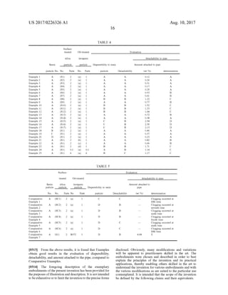
This document describes a resin particle composition containing resin particles, inorganic particles surface-treated with oil, and silica particles. The silica particles have specific properties including a compression aggregation degree of 60-95% and a particle compression ratio of 0.20-0.40. These specific silica particles improve the dispersibility of the oil-treated inorganic particles to the resin particles and increase the lubrication function, preventing fixation of the resin particle composition in pipes during air transportation.
Deep Leg Vein Thrombosis (DVT): Meaning, Causes, Symptoms, Treatment, and Mor...The Lifesciences Magazine
Deep Leg Vein Thrombosis occurs when a blood clot forms in one or more of the deep veins in the legs. These clots can impede blood flow, leading to severe complications.
Deep Leg Vein Thrombosis (DVT): Meaning, Causes, Symptoms, Treatment, and Mor...The Lifesciences Magazine
Deep Leg Vein Thrombosis occurs when a blood clot forms in one or more of the deep veins in the legs. These clots can impede blood flow, leading to severe complications.
India Clinical Trials Market: Industry Size and Growth Trends [2030] Analyzed...Kumar Satyam
According to TechSci Research report, "India Clinical Trials Market- By Region, Competition, Forecast & Opportunities, 2030F," the India Clinical Trials Market was valued at USD 2.05 billion in 2024 and is projected to grow at a compound annual growth rate (CAGR) of 8.64% through 2030. The market is driven by a variety of factors, making India an attractive destination for pharmaceutical companies and researchers. India's vast and diverse patient population, cost-effective operational environment, and a large pool of skilled medical professionals contribute significantly to the market's growth. Additionally, increasing government support in streamlining regulations and the growing prevalence of lifestyle diseases further propel the clinical trials market.
Growing Prevalence of Lifestyle Diseases
The rising incidence of lifestyle diseases such as diabetes, cardiovascular diseases, and cancer is a major trend driving the clinical trials market in India. These conditions necessitate the development and testing of new treatment methods, creating a robust demand for clinical trials. The increasing burden of these diseases highlights the need for innovative therapies and underscores the importance of India as a key player in global clinical research.
India Diagnostic Labs Market: Dynamics, Key Players, and Industry Projections...Kumar Satyam
According to the TechSci Research report titled “India Diagnostic Labs Market Industry Size, Share, Trends, Competition, Opportunity, and Forecast, 2019-2029,” the India Diagnostic Labs Market was valued at USD 16,471.21 million in 2023 and is projected to grow at an impressive compound annual growth rate (CAGR) of 11.55% through 2029. This significant growth can be attributed to various factors, including collaborations and partnerships among leading companies, the expansion of diagnostic chains, and increasing accessibility to diagnostic services across the country. This comprehensive report delves into the market dynamics, recent trends, drivers, competitive landscape, and benefits of the research report, providing a detailed analysis of the India Diagnostic Labs Market.
Collaborations and Partnerships
Collaborations and partnerships among leading companies play a pivotal role in driving the growth of the India Diagnostic Labs Market. These strategic alliances allow companies to merge their expertise, strengthen their market positions, and offer innovative solutions. By combining resources, companies can enhance their research and development capabilities, expand their product portfolios, and improve their distribution networks. These collaborations also facilitate the sharing of technological advancements and best practices, contributing to the overall growth of the market.
Expansion of Diagnostic Chains
The expansion of diagnostic chains is a driving force behind the growing demand for diagnostic lab services. Diagnostic chains often establish multiple laboratories and diagnostic centers in various cities and regions, including urban and rural areas. This expanded network makes diagnostic services more accessible to a larger portion of the population, addressing healthcare disparities and reaching underserved populations. The presence of diagnostic chain facilities in multiple locations within a city or region provides convenience for patients, reducing travel time and effort. A broader network of labs often leads to reduced waiting times for appointments and sample collection, ensuring that patients receive timely and efficient diagnostic services.
Rising Prevalence of Chronic Diseases
The increasing prevalence of chronic diseases is a significant driver for the demand for diagnostic lab services. Chronic conditions such as diabetes, cardiovascular diseases, and cancer require regular monitoring and diagnostic testing for effective management. The rise in chronic diseases necessitates the use of advanced diagnostic tools and technologies, driving the growth of the diagnostic labs market. Additionally, early diagnosis and timely intervention are crucial for managing chronic diseases, further boosting the demand for diagnostic lab services.
For those battling kidney disease and exploring treatment options, understanding when to consider a kidney transplant is crucial. This guide aims to provide valuable insights into the circumstances under which a kidney transplant at the renowned Hiranandani Hospital may be the most appropriate course of action. By addressing the key indicators and factors involved, we hope to empower patients and their families to make informed decisions about their kidney care journey.
The dimensions of healthcare quality refer to various attributes or aspects that define the standard of healthcare services. These dimensions are used to evaluate, measure, and improve the quality of care provided to patients. A comprehensive understanding of these dimensions ensures that healthcare systems can address various aspects of patient care effectively and holistically. Dimensions of Healthcare Quality and Performance of care include the following; Appropriateness, Availability, Competence, Continuity, Effectiveness, Efficiency, Efficacy, Prevention, Respect and Care, Safety as well as Timeliness.
CHAPTER 1 SEMESTER V PREVENTIVE-PEDIATRICS.pdfSachin Sharma
This content provides an overview of preventive pediatrics. It defines preventive pediatrics as preventing disease and promoting children's physical, mental, and social well-being to achieve positive health. It discusses antenatal, postnatal, and social preventive pediatrics. It also covers various child health programs like immunization, breastfeeding, ICDS, and the roles of organizations like WHO, UNICEF, and nurses in preventive pediatrics.
Empowering ACOs: Leveraging Quality Management Tools for MIPS and BeyondHealth Catalyst
Join us as we delve into the crucial realm of quality reporting for MSSP (Medicare Shared Savings Program) Accountable Care Organizations (ACOs).
In this session, we will explore how a robust quality management solution can empower your organization to meet regulatory requirements and improve processes for MIPS reporting and internal quality programs. Learn how our MeasureAble application enables compliance and fosters continuous improvement.
The Importance of Community Nursing Care.pdfAD Healthcare
NDIS and Community 24/7 Nursing Care is a specific type of support that may be provided under the NDIS for individuals with complex medical needs who require ongoing nursing care in a community setting, such as their home or a supported accommodation facility.
1. (19) United States
US 20170226326A1
(12) Patent Application Publication (10) Pub. No.: US2017/0226326A1
TAKEUCH et al. (43) Pub. Date: Aug. 10, 2017
(54) RESIN PARTICLE COMPOSITION
(71) Applicant: FUJI XEROX CO., LTD., Tokyo (JP)
(72) Inventors: Sakae TAKEUCHI, Kanagawa (JP):
Hiroyoshi OKUNO, Kanagawa (JP):
Satoshi INOUE, Kanagawa (JP);
Yoshifumi IIDA, Kanagawa (JP);
Yasuo KADOKURA, Kanagawa (JP);
Tomohito NAKAJIMA, Kanagawa
(JP): Takeshi IWANAGA, Kanagawa
(JP); Shunsuke NOZAKI, Tokyo (JP);
Yuka ZENITANI, Kanagawa (JP);
Yoshifumi ERI, Kanagawa (JP);
Yasuhisa MOROOKA, Kanagawa (JP)
(73) Assignee: FUJI XEROX CO., LTD., Tokyo (JP)
(21) Appl. No.: 15/207,990
(22) Filed: Jul. 12, 2016
(30) Foreign Application Priority Data
Feb. 10, 2016 (JP) ................................. 2O16-O241.38
Publication Classification
(51) Int. Cl.
CSK 9/06
(52) U.S. Cl.
CPC ...................................... C08K9/06 (2013.01)
(2006.01)
(57) ABSTRACT
A resin particle composition includes resin particles, inor
ganic particles Surface-treated with oil, and silica particles
having a compression aggregation degree of 60% to 95%
and a particle compression ratio of 0.20 to 0.40.
ungwaniL (JP)gawaKanaMuungo,
2. US 2017/0226326 A1
RESIN PARTICLE COMPOSITION
CROSS-REFERENCE TO RELATED
APPLICATIONS
0001. This application is based on and claims priority
under 35 USC 119 from Japanese Patent Application No.
2016-024138, filed Feb. 10, 2016.
BACKGROUND
0002 1. Technical Field
0003. The present invention relates to a resin particle
composition.
0004 2. Related Art
0005. A resin particle composition has been applied as
various applications such as a binder.
0006. Here, in the resin particle composition, for
example, silica particles may be used together with resin
particles in orderto improvethe strengthandfluidity ofresin
particles and prevent the packing of resin particles. In
particular, powder, Such as resin particles, is often subjected
to a transportation method (hereinafter, also referred to as
“air transportation') in which powder is transported by air
flowing in a pipe. In the application of this transportation
method, the improvement in fluidity of resin particles is
significant.
SUMMARY
0007 According to an aspect of the invention, there is
provided a resin particle composition, including:
0008 resin particles;
0009 inorganic particles surface-treated with oil; and
0010 silica particles having a compression aggregation
degree of 60% to 95% and a particle compression ratio of
O2O to 0.40.
DETAILED DESCRIPTION
0011. Hereinafter, exemplary embodiments ofthepresent
invention will be described.
0012. A resin particle composition, forexample, includes
inorganic particles Surface-treated with oil (hereinafter,
referred to as “oil-treated inorganic particles') together with
resin particles, thereby imparting functionality, Such as
lubricity, to resin particles.
0013 Resin Particle Composition
0014. The resin particle composition according to the
exemplary embodiment includes resin particles, oil-treated
inorganicparticles,and silicaparticleshavingacompression
aggregation degree of 60% to 95% and a particle compres
sion ratio of0.20to 0.40(hereinafter, referred to as “specific
silica particles').
0015 The resin particle composition according to the
exemplary embodimenthas theabove configuration, thereby
preventing the fixation ofthe resin particle composition into
the pipe in the case oftransporting the resin particle com
position using air. The reason for this is not clear, but it is
considered to be due to the following reasons.
0016. It is considered that, when the compression aggre
gation degree and particle compression ratio ofthe specific
silica particles are within the above ranges, respectively, the
following effects are exhibited.
0017 First, the significance of setting the compression
aggregation degree ofthe specific silica particles to 60% to
95% will be described.
Aug. 10, 2017
0018. The compression aggregation degree is an index
indicating the aggregability ofsilica particles and the adhe
siveness of silica particles to resin particles. This index is
indicated by the degree ofunraveling difficulty ofa compact
obtained by compressing silica particles when dropping the
compact of silica particles.
0019. Thus, as the compression aggregation degree
increases, the aggregation force (intermolecular force) of
silica particles tends to become stronger, and the adhesion
force of silica particles to resin particles also Lends to be
stronger. The details ofthe method ofcalculating the com
pression aggregation degree will be described later.
0020. Therefore, the specific silica particles, the com
pression aggregation degree ofwhich is highly controlled in
a range of 60% to 95%, have good aggregability and good
adhesiveness to resin particles. However, from the view
point of securing the fluidity of silica particles and the
dispersibility of silica particles to resin particles while
maintaining good aggregability of silica particles and good
adhesiveness ofsilica particles to toner particles, the upper
limit value ofthe compression aggregation degree is set to
95%.
0021 Next, the significance of setting the particle com
pression ratio ofthe specific silica particles to 0.20 to 0.40
will be described.
0022. The particle compression ratio is an index indicat
ing the fluidity of silica particles. Specifically, the particle
compression ratio is indicated by the ratio of difference
between compressed apparent specific gravity and loose
apparent specific gravity of silica particles to compressed
apparent specific gravity of silica particles (compressed
apparent specific gravity—loose apparent specific gravity)/
compressed apparent specific gravity).
0023 Thus, as the particle compression ratio decreases,
the fluidity of silica particles increases. Further, as the
fluidity of silica particles increases, the dispersibility of
silica particles to resin particles tends to become high. The
details ofthe method ofcalculatingtheparticle compression
ratio will be described later.
0024. Therefore, the specific silica particles, the particle
compression ratio ofwhich is lowly controlled in a range of
0.20 to 0.40, have good fluidity and good dispersibility to
resin particles. However, from the viewpoint of improving
the aggregability ofsilica particles and the adhesiveness of
silica particles to resin particles while maintaining good
fluidity of silica particles and good dispersibility of silica
particles to resin particles, the lower limit value of the
particle compression ratio is set to 0.20.
0025. From the above, the specific silica particles are
characterized in that they areeasily fluidized, they are easily
dispersed in resin particles, and they have high aggregation
forceandhigh adhesion forceto resinparticles. Accordingly,
the specific silica particles, the compression aggregation
degree and particle compression ratio of which satisfy the
above range, are silica particles having properties of high
fluidity, high dispersibility to resin particles, high aggre
gability, and high adhesiveness to resin particles.
0026. Next, estimated effects at the time of using resin
particles and oil-treated inorganic particles and furtherusing
specific silica particles will be described.
0027 First, since the specific silica particles have high
fluidity and high dispersibility to resin particles, they easily
adhere to the Surface ofresin particles in an almost uniform
state when they are mixed with resin particles.
3. US 2017/0226326 A1
0028. Further, when resin particles and oil-treated inor
ganic particles are used and the specific silica particles are
further used, the oil-treated inorganic particles (including oil
liberated from the oil-treated inorganic particles) easily
adhere to the resin particles together with the specific silica
particles. Therefore, the dispersibility of the oil-treated
inorganic particles to the resin particles easily increases, and
thus the oil-treated inorganic particles easily adhere to the
resin particles in an almost uniform state.
0029. Meanwhile, since the specific silica particles
adhered to the surface ofthe resin particles once have high
adhesiveness to the resin particles, it is difficult to cause the
movement on the resin particles and the liberation from the
resin particles at a load attributable to the airflow occurring
when transporting the resin particle composition using air.
0030. Further, the oil-treated inorganic particles (includ
ing oil liberated from the oil-treated inorganic particles)
adhered to the resin particles togetherwith the specific silica
particles arealso easily immobilized on theresin particlesby
the oil on the surface thereof. Therefore, in the resin particle
composition, it is difficultto change a structure in which the
specific silica particles and the oil-treated inorganic particles
adhere to the resin particles.
0031. As a result, it is considered that the resin particle
composition of the exemplary embodiment exhibits an
increased lubrication function, thereby preventing the fixa
tion ofthe resinparticlecomposition into thepipe inthecase
of transporting the resin particle composition using air.
0032. From the above, it is estimated that the specific
silica particles are used together with the resin particles and
the oil-treated inorganic particles, thereby preventing the
fixation ofthe resin particle composition of the exemplary
embodiment into the pipe in the case of transporting the
resin particle composition using air.
0033. The resin particle composition has also the follow
ing characteristics due to theaggregability and fluidity ofthe
specific silica particles.
0034. When the specific silica particles are further mixed
with the resin particles and the oil-treated inorganic par
ticles, the specific silica particles adhere to the resin par
ticles, and thus the resin particle composition is difficult to
scatter in the air. Further, since the specific silica particles
adhere to the resin particles, the aggregation of the resin
particle composition is easily relaxed and the reflow ofthe
resin particle composition becomes easy by the airflow
occurring when transporting the resin particle composition
using air even in the case ofoccurrence ofthe aggregation
of the resin particle composition.
0035. In the resin particle composition according to the
exemplary embodiment, it is preferable that the particle
dispersion degree of the specific silica particles is 90% to
100%.
0036. Here, the significance of setting the particle dis
persion degreeofthe specific silica particles to 90% to 100%
will be described.
0037. The particle dispersion degree is an index indicat
ing the dispersibility of silica particles. This index is indi
cated by the degree of easiness of dispersion of silica
particles to resin particles in the primary particle state.
Specifically, the particle dispersion degree is indicated by
the ratio of actually-measured coverage C to calculated
coverage Co (actually-measured coverage C/calculated cov
erage Co) when the calculated coverage of resin particles
Aug. 10, 2017
with silica particles is represented by Co and the actually
measured coverage thereof is represented by C.
0038. Therefore, as the particle dispersion degree
increases, silica particles are difficult to aggregate, and are
easy to be dispersed to the resin particles in the primary
particle state. The details of the method ofcalculating the
particle dispersion degree will be described later.
0039. The dispersibility ofthe specific silica particles to
the resin particles is further improved by controlling the
particle dispersion degree to 90% to 100% at a high level
while controlling the compression aggregation degree and
the particle compression ratio within the above range. Thus,
the oil-treated inorganic particles in the resin particle com
position have higher dispersibility to the surface ofthe resin
particles. As a result, the resin particle composition exhibits
high lubrication function in thepipe, thereby easily prevent
ing the fixation oftheresin particlecomposition into thepipe
in the case of transporting the resin particle composition
using air.
0040. In the resin particle composition according to the
exemplary embodiment, as described above, as the specific
silica particles, which have properties of high fluidity and
high dispersibility to resin particles, high aggregability, and
high adhesiveness to resin particles, silica particles, the
Surfaces of which are coated with a siloxane compound
having a relatively large weight average molecular weight,
are preferably exemplified. Specifically, silica particles, the
Surfaces of which are coated with a siloxane compound
havinga viscosity of1,000 cSt to 50,000 cSt (preferably, the
surface coated amount ofthe siloxane compound is 0.01%
by weight to 5% by weight), are preferably exemplified.
These specific silica particles are obtained by a surface
treatment method in which thesurfacesofsilica particles are
treated with a siloxane compound having a viscosity of
1,000 cSt to 50,000cSt Such that the surface coated amount
is 0.01% by weight to 5% by weight.
0041. Here, the surface coated amount is referred to as
the rate of Surface-treated silica particles to silica particles
before the surface treatment (untreated silica particles).
Hereinafter, the silica particles before the surface treatment
(that is, untreated silica particles) are simply referred to as
“silica particles”.
0042. The specific silica particles, the surfaces ofwhich
are treated with a siloxane compound having a viscosity of
1,000 cSt to 50,000cSt Such that the surface coated amount
is 0.01% by weightto 5% by weight, havehigh aggregability
and high adhesiveness to resin particles as well as high
fluidity and high dispersibility to resin particles, and the
compression aggregation degree and particle compression
ratio thereofeasily satisfy the above requirements. Further,
in the case of transporting the resin particle composition
using air, the fixation of the resin particle composition into
the pipe is easily prevented. The reason for this is not clear,
but it is considered to be due to the following reasons.
0043. When the siloxane compound having relatively
high viscosity within the above range adheres to the Surface
ofsilica particles in a small amount within the above range,
the function derived from the properties of the siloxane
compound on the Surface ofthe silica particles is expressed.
Althoughthe mechanism is notclear, whenthespecific silica
particles are fluidized, the releasing properties derived from
the siloxane compound are easily expressed by adhering a
Small amount of the siloxane compound having relatively
high viscosity to the surface thereofwithin the above range,
4. US 2017/0226326 A1
or the adhesiveness between the silica particles is deterio
rated by the reduction of the inter-particle force due to the
sterichindranceofthe siloxane compound.Thus, thefluidity
ofsilica particles and the dispersibility ofsilica particles to
resin particles increase.
0044) Meanwhile, when the silica particles are com
pressed, the long molecular chains of the siloxane com
pound ofthe Surface ofthe silica particles are entangled, so
that the closest packing properties of the silica particles
increase, and the aggregation force between the silica par
ticles is intensified. Further, it is considered that the aggre
gation force ofthe silica particles dueto theentanglement of
the long molecular chains of this siloxane compound is
released by fluidizing the silica particles. In addition to this,
the adhesion force ofthe silica particles to resin particles is
also increased by the long molecular chains ofthe siloxane
compound ofthe Surface of the silica particles.
0045. From the above, in the specific silica particles, in
which the siloxane compound having viscosity within the
above range adheres to the Surface of silica particles in a
Small amount within the above range, the compression
aggregation degree and particle compression ratio thereof
easily satisfy the above requirements, and the particle dis
persion degree thereofalso easily satisfy the above require
mentS.
0046. Hereinafter, the configuration of the resin particle
composition will be described.
0047 First, the specific silica particles will be described.
0048 Specific Silica Particles
0049. The specific silica particles have a compression
aggregation degree of 60% to 95% and a particle compres
Sion ratio of 0.20 to 0.40.
0050 First, the characteristics of silica particles will be
described in detail.
0051 Compression Aggregation Degree
0.052 Thecompression aggregation degree ofthespecific
silica particles, from the viewpointofsecuringthe fluidity of
the specific silica particles and the dispersibility of the
specific silica particles to resin particles while maintaining
good aggregability of the specific silica particles and good
adhesiveness ofthe specific silica particles to resin particles
(particularly, from the viewpoint ofpreventing the fixation
of the resin particle composition into the pipe when trans
porting the resin particle composition using air), is 60% to
95%, preferably 65% to 95%, and more preferably 70% to
95%.
0053. The compression aggregation degree is calculated
by the following method.
0054. A disc-shaped mold having a diameter of 6 cm is
filled with 6.0 g of the specific silica particles. Next, the
moldiscompressedfor60secondsbyapressureof5.0t/cm
using a compression molding machine (manufactured by
Maekawa Testing Machine MFG Co., Ltd.), so as to obtain
a compressed disc-shaped compact of the specific silica
particles (hereinafter, referred to as “compact before fall
ing'). Thereafter, the weightofthe compact before falling is
measured.
0055 Next, the compact before falling is placed on a
sieve Screen having a mesh opening of600 um, and is fallen
by a vibration sieve machine (part number: VIBRATING
MVB-1, manufactured by TSUTSUI SCIENTIFIC
INSTRUMENTS CO.,LTD.) underthe conditions ofampli
tude of 1 mm and vibration time for 1 minute. Thus, the
specific silica particles are fallen from the compact before
Aug. 10, 2017
falling through the sieve Screen, and the compact of the
specific silica particles remains on the sieve Screen. There
after, the weight of the remaining compact of the specific
silica particles (hereinafter, referred to as “compact after
falling) is measured.
0056. Then, the compression aggregation degree is cal
culated from the ratio of weight ofcompact after falling to
weight ofcompact before falling, using Equation (1) below.
compression aggregation degree (weight of compact
after falling weight of compact before falling)x
100 Equation (1):
0057 Particle Compression Ratio
0058. Theparticle compression ratio ofthe specific silica
particles, from the viewpoint ofsecuringtheaggregability of
the specific silica particles and the dispersibility of the
specific silica particles to resin particles while maintaining
good fluidity of the specific silica particles and good adhe
siveness of the specific silica particles into resin particles
(particularly, from the viewpoint ofpreventing the fixation
of the resin particle composition into the pipe when trans
porting the resin particle composition using air), is 0.20 to
0.40, preferably 0.24 to 0.38, and more preferably 0.28 to
O.36.
0059. The particle compression ratio is calculated by the
following method.
0060. The compressed apparent specific gravity and
loose apparent specific gravity of silica particles are mea
Sured using a powder tester (manufactured by Hosokawa
Micron Corporation, part number PT-S type). Then, the
particle compression ratio is calculated from the ratio of
difference between compressed apparent specific gravity
and loose apparent specific gravity of silica particles to
compressed apparent specific gravity, using Equation (2)
below.
particle compression ratio (compressed apparent
specific gravity-loose apparent specific gravity),
compressed apparent specific gravity Equation (2):
0061 Here, the “loose apparent specific gravity” is a
measurement value derived by filling a container having a
volume of 100 cm with silica particles and weighing the
container filled with the silica particles, and refers to filling
specific gravity in a state ofthe specific silica particles being
naturally fallen into the container. The “compressed appar
ent specific gravity” refers to apparent specific gravity ofthe
specific silica particles which are degased, rearranged and
more densely packed by repeatedly applying an impact to
the bottom of the container (tapping the bottom of the
container) at a stroke length of 18 mm and a tapping speed
of 50 times/min 180 times from the state ofloose apparent
specific gravity.
0062
0063. The particle dispersion degree ofthe specific silica
particles, from the viewpoint offurther improving the dis
persibility of the specific silica particles to resin particles
(particularly, from the viewpoint ofpreventing the fixation
of the resin particle composition into the pipe when trans
porting the resin particle composition using air), is prefer
ably 90% to 100%, and more preferably 95% to 100%.
0064. The particle dispersion degree refers to the ratio of
actually-measured coverage C of resin particles with the
Particle Dispersion Degree
5. US 2017/0226326 A1
specific silica particles to calculated coverage Co., and is
calculated using Equation (3) below.
particle dispersion degree-actually-measured cover
age C calculated coverage Co Equation (3):
0065 Here, the calculated coverage Co ofthe surface of
resin particles with the specific silica particles may be
calculated using Equation (3-1) below, when the Volume
average particle diameter ofresin particles is represented by
dt (m), the average circle-equivalent diameter ofthe specific
silica particles is represented by da (m), the specific gravity
ofresin particles is represented by pt, the specific gravity of
the specific silica particles is represented by pa, the weight
ofresin particles is represented by Wt (kg), and the addition
amount ofthe specific silica particles is represented by Wa
(kg).
calculated coverage Cov3/(2T)x(pt/pa)x(dt/da)x
(Wa/Wi)x100(%) Equation (3-1):
0066. Theactually-measuredcoverageCofthe surfaceof
resin particles with the specific silica particles may be
calculated using Equation (3-2) below, after the signal
intensities of silicon atoms derived from the specific silica
particles are measured with respect to only the resin par
ticles, onlythe specific silica particles,and the resin particles
including the specific silica particles, respectively, by an
X-ray photoelectron spectroscopy (XPS) (“JPS-9000MX,
manufactured by JEOL Ltd.).
actually-measured coverage C-(Z-x)/(y-x)x100(%) Equation (3-2):
0067. In Equation (3-2), X represents signal intensity of
silicon atoms derived from the specific silica particles with
respect to only the resin particles. y represents signal inten
sity ofsilicon atoms derived from the specific silica particles
with respect to only the specific silica particles. Z represents
signal intensity of silicon atoms derived from the specific
silica particles with respect to the resin particles coated
(covered) with the specific silica particles.)
0068
0069. The average circle-equivalent diameter ofthe spe
cific silica particles, from the viewpoint of improving flu
idity, dispersibility to resin particles, aggregability, and
adhesiveness to resin particles (particularly, from the view
point ofpreventing the fixation ofthe resin particle compo
sition into the pipe when transporting the resin particle
composition using air), is preferably 40 nm to 200 nm, more
preferably 50 nm to 180 nm, and further more preferably 60
nm to 160 nm.
0070 The average circle-equivalent diameter D50 ofthe
specific silica particles are obtained as follows. Primary
particles after dispersing the specific silica particles into
resin particles are observed by a scanning electron micro
scope (SEM) (S-4100, manufactured by Hitachi, Ltd.) to
capture an image, this image is put into an image analyZer
(LUZEXIII, manufactured by Nireco Corporation), the area
of each particle is measured by the image analysis of the
primary particles, and the circle-equivalent diameter of the
particle is calculated from this area value. The diameter
corresponding to 50% in the cumulative frequency in terms
ofvolume basisofthe obtained circle-equivalent diameteris
set to the average circle-equivalent diameter D50 of the
specific silica particles. In addition, the magnification ofthe
electron microscope is adjusted such that 10 to 50 specific
silica particles appear in one field of view, and the circle
Average Circle-Equivalent Diameter
Aug. 10, 2017
equivalent diameter of the primary particle is obtained in
combination with observations in multiple fields of view.
0071 Average Circularity Degree
0072 Although the shape of the specific silica particles
may be any of a spherical shape and different shapes, the
average circularity degree of the specific silica particles,
from the viewpoint of improving fluidity, dispersibility to
resin particles, aggregability, and adhesiveness to resin
particles in thespecific silica particles (particularly, from the
viewpoint of preventing the fixation of the resin particle
composition into the pipe when transporting the resin par
ticle composition using air), is preferably 0.85 to 0.98, more
preferably 0.90 to 0.98, and further more preferably 0.93 to
O.98.
0073. Theaverage circularity degree ofthe specific silica
particles is measured by the following method.
0074 First, the circularity degree of the specific silica
particles is obtained as “100/SF2’ calculated by the follow
ing equation, from the analysis ofthe planar image obtained
by observing the primary particles after adhering silica
particles to the surface of resin particles by SEM.
circularity degree (100/SF2)=41x(A/I)
0075 (In the equation, I represents a boundary length of
primary particles in an image, and A represents a projected
area ofprimary particles.)
0076 Further, the average circularity degree of the spe
cific silica particles is obtained as 50% circularity degree in
the cumulative frequency of circularity degree of 100 pri
mary particles obtained by the above planar image analysis.
0077. Here, a method of measuring the characteristics
(compression aggregation degree, particle compression
ratio, particle dispersion degree, and average circularity
degree) of the specific silica particles in the resin particle
composition will be described.
0078 First, specific silica particles and oil-treated inor
ganic particles are separated from the resin particle compo
sition as follows. The resin particle composition is dispersed
in methanol, stirred, and then ultrasonically treated with an
ultrasonic bath, so as to separate the specific silica particles
and oil-treated inorganic particles from the resin particle
composition. The easiness of the separation ofthe specific
silica particles and oil-treated inorganic particles is deter
mined by the particle diameter and specific gravity of the
specific silica particles and oil-treated inorganic particles.
Since the specific silica particles havinga large diameterare
easy to separate, only the specific silica particles are sepa
rated by setting the ultrasonic treatment condition to a weak
condition.
0079. Next, the ultrasonic treatment conditions are
changed to a strong condition, and the oil-treated inorganic
particles are separated from the Surface of resin particles.
The resin particles are precipitated by centrifugation to
collect only the methanol dispersed with the specific silica
particles or the oil-treated inorganic particles, and then this
methanol is volatilized, so as to take out the specific silica
particles or the oil-treated inorganic particles. In this ultra
Sonic treatment condition, a separation condition is adjusted
by the specific silica particles and the oil-treated inorganic
particles.
0080. Then, the above characteristics are measured using
the separated specific silica particles.
I0081. Next, the configuration of the specific silica par
ticles will be described.
Equation:
6. US 2017/0226326 A1
0082 Silica Particles
0083. The specific silica particles, which are particles
containing silica (that is, SiO) as a main component, may
be crystalline particles or amorphous particles. The specific
silica particles may be particles prepared using a silicon
compound, Such as water glass or alkoxysilane, as a raw
material, and may also be particles obtained by pulverizing
quartZ.
0084 Examples of the specific silica particles include
silica particles fabricated by a sol-gel process (hereinafter,
referred to as “sol-gel silica particles'), aqueous colloidal
silica particles, alcoholic silica particles, fumed silica par
ticles obtained by a gas-phase process, and molten silica
particles.Amongthesesilica particles, Sol-gel silicaparticles
are preferable.
0085 Surface Treatment
I0086. It is preferable that the specific silica particles are
Surface-treated with a siloxane compound in order to allow
the compression aggregation degree, particle compression
ratio and particle dispersion degree thereof to be within the
above specific range.
0087 As the surface treatment method, it is preferable to
perform the surface treatment to the surface of silica par
ticles in Supercritical carbon dioxide using the Supercritical
carbon dioxide. The surface treatment method will be
described later.
I0088 Siloxane Compound
0089. The siloxane compound is not particularly limited
as longas ithas a siloxane skeleton in a molecular structure.
0090. Examples of the siloxane compound include sili
cone oil and silicone resin. Among these, silicone oil is
preferable, from the viewpoint of surface-treating the sur
face ofsilica particles in an almost uniform state.
0091 Examples ofsilicone oil include dimethyl silicone
oil, methyl hydrogen silicone oil, methylphenyl silicone oil,
amino-modified silicone oil, epoxy-modified silicone oil,
carboxyl-modified silicone oil, carbinol-modified silicone
oil, methacryl-modified silicone oil, mercapto-modified sili
cone oil, phenol-modified silicone oil, polyether-modified
silicone oil, methylstyryl-modified silicone oil, alkyl-modi
fied silicone oil, higher fatty acid ester-modified silicone oil,
higher fatty acid amide-modified silicone oil, and fluorine
modified silicone oil. Among these, dimethyl silicone oil,
methyl hydrogen silicone oil, and amino-modified silicone
oil are preferable.
0092. The above siloxane compound may be used alone
or in combination of two or more.
0093. Viscosity
0094. The viscosity (kinetic viscosity) of the siloxane
compound, from the viewpoint of improving fluidity, dis
persibility to resin particles, aggregability and adhesiveness
to resin particles in the specific silica particles (particularly,
from the viewpoint of preventing the fixation of the resin
particle composition into the pipe when transporting the
resin particle composition using air), is preferably 1,000 cSt
to 50,000 cSt, more preferably 2,000 cSt to 30,000 cSt, and
further more preferably 3,000 cSt to 10,000 cSt.
0095. The viscosity ofthe siloxanecompound is obtained
by the following procedure. Toluene is added to the specific
silica particles, and then the specific silica particles are
dispersed in the toluene for 30 minutes by an ultrasonic
dispersing machine. Thereafter, Supernatant is collected. At
thistime,atoluene Solution containing a siloxanecompound
Aug. 10, 2017
in a concentration of 1 g/100 ml is obtained. The specific
viscosity msp (25°C.) at this time is obtained by Equation
(A) below.
insp=(minO)-1
0096 (mo: Viscosity oftoluene, m: viscosity ofsolution)
0097 Next, the specific viscosity msp is substituted into
the Huggins Equation representedby Equation (B) below, so
as to obtain intrinsic viscosity m.
(0098 (K': Huggins's constant, K=0.3 (m=1 to 3))
0099 Next, the intrinsic viscosity Im is substituted into
the A. Kolorlov Equation represented by Equation (C)
below, so as to obtain molecular weight M.
Equation (A):
Equation (B):
m=0.215x10 Moss
0100 Next, the molecular weight M is substituted into
theA. J. Barry Equation represented by Equation (D) below,
So as to obtain siloxane Viscosity .
Equation (C):
log m=1.00+0.0123M
0101 Surface Coated Amount
0102 The amount ofthe siloxane compound adhered to
thesurfaceofthe specific silica particles, from the viewpoint
ofimproving fluidity, dispersibility to resin particles, aggre
gability, and adhesiveness to resin particles in the specific
silica particles (particularly, from the viewpoint ofprevent
ing the fixation oftheresin particlecomposition into thepipe
when transporting the resin particle composition using air).
is preferably 0.01% by weight to 5% by weight, more
preferably 0.05% by weight to 3% by weight, and further
more preferably 0.10% by weight to 2% by weight with
respect to silica particles (silica particles before surface
treatment).
0103) The surface coated amount is measured by the
following method.
0104 100 mg ofthe specific silica particles are dispersed
in 1 mL of chloroform, and 1 uL of DMF (N,N-dimethyl
formamide), as an internal standard solution, is added
thereto, followed by ultrasonic treatment for 30 minutes
with an ultrasonic cleaning machine, so as to extract a
siloxane compound into the chloroform solvent. Thereafter,
hydrogen nucleus spectrum measurement is performed by a
JNM-AL400 type nuclear magnetic resonance apparatus
(manufactured by JEOL Ltd.), and the amount ofthe silox
ane compound is obtained from the ratio of a siloxane
compound-derived peak area to a DMF-derived peak area.
Then, the surface coated amount is calculated from the
obtained amount ofthe siloxane compound and the amount
of silica particles, from which the siloxane compound is
liberated, (silica particles, to the surface ofwhich the silox
ane compound is not adhered).
0105. The viscosity of the siloxane compound of the
specific silica particles and Surface coated amount are mea
Sured by separating the specific silica particles and the
oil-treated inorganic particles from the resin particle com
position using the above-described method.
0106 Here, the specific silica particles aresurface-treated
with a siloxanecompound having a viscosity of1,000cSt to
50,000 cSt, and the surface coated amount of the siloxane
compound to the Surface of silica particles is preferably
0.01% by weight to 5% by weight.
0107. When the above requirements are satisfied, the
specific silica particles having good fluidity and good dis
Equation (D):
7. US 2017/0226326 A1
persibility to resin particles and having improved aggre
gability and adhesiveness to resin particles are easily
obtained.
0108 Resin Particles
0109) Next, the resin particles will be described.
0110. The resin particles are not particularly limited as
long as they have a shape, diameter, and material (compo
nent) required foradheringthe specific silica particles to the
resin particles. The resin particles may be determined
depending on the application purpose of the resin particle
composition according to the exemplary embodiment.
0111. The shape of the resin particles is not particularly
limited, butthe volume averageparticle diameterofthe resin
particles is preferably 1 um to 20 Lum, more preferably 2 um
to 15um, and further more preferably 3 um to 10 um. When
the Volume average particle diameter ofthe resin particles is
within the above range, the deterioration of fluidity of the
resin particle composition is easily prevented.
0112 Here, the volume average particle diameter of the
resin particles is measured using COULTER MULTISIZER
II (manufactured by Beckman Coulter, Inc.). In this mea
surement, ISOTON-II (manufactured by Beckman Coulter,
Inc.) is used for measuring an electrolyte.
0113. In the measurement, 0.5 mg to 50 mg of a mea
Surement sample is added to 2 ml of an aqueous solution
containing 5% by weight of a Surfactant, such as sodium
alkylbenzene Sulfonate, as a dispersant. This resultant is
added to 100 ml to 150 ml ofan electrolyte.
0114. The electrolyte in which the sample has been
Suspended is dispersion-treated for 1 minute with an ultra
Sonic dispersing machine, and the particle size distribution
of particles within a range of 2 um to 50 Lum is measured
using an aperture having a diameter of 100 um by
COULTER MULTISIZER II. The number ofparticles to be
sampled is 50,000.
0115 The volume average particle diameter Ds is
defined by the particle diameter at 50% cumulative volume
when drawing the cumulative distribution ofthe measured
particle size distributions with respect to the divided par
ticles size ranges (channels) from Small diameter for Vol
ume. Specifically, the Volumeaverage particle diameter Dso
is obtainedas follows. The volumeaverage particle diameter
Dso at 50% cumulative volume is obtained by drawing a
cumulative distribution using the volume distribution
obtained by image analysis.
0116. The resin constituting the resin particles is not
particularly limited. As the resin constituting the resin par
ticles, thermoplastic resins made of various natural or syn
thetic polymer materials may be used.
0117 Examples of the resin include polyolefin resins,
Such as polyethylene and polypropylene; polystyrene resins,
Such as polystyrene and an acrylonitrile/butadiene/styrene
copolymer (ABS resin); acrylic resins, such as polymethyl
methacrylate and polybutyl acrylate; rubbery (co)polymers,
Such as polybutadiene and polyisoprene; polyester resins,
Such as polyethylene terephthalate and polybutylene
terephthalate, vinyl resins, such as vinyl chloride resin, vinyl
aromatic resin, and polyvinyl resin: epoxy resins; conju
gated diene resins; polyamide resins; polyacetal resins;
polycarbonate resins; thermoplasticpolyurethaneresins; and
fluorine resins.
0118. These resins may be used alone or as a mixture of
two or more thereof.
Aug. 10, 2017
0119) As the resin constituting the resin particles, typi
cally, resins having a weight average molecular weight of
5,000 to 100,000 (for example, epoxy resins, styrene-acry
late resins, polyamide resins, polyester resins, polyvinyl
resins, polyolefin resins, polyurethane resins, and polybuta
diene resins) are exemplified. These resins may be used
alone or as a mixture of two or more thereof.
0.120. The resin particles may furthercontain an additive,
Such as an ultraviolet absorber oran antioxidant, depending
on the intended use.
I0121 Oil-Treated Inorganic Particles
I0122) Next, the oil-treated inorganic particles will be
described.Theoil-treatedinorganicparticles areobtainedby
treating the Surface of inorganic particles with oil. That is,
the oil-treated inorganic particles are inorganic particles
obtained by adhering oil tothe Surface ofuntreated inorganic
particles.
I0123 Inorganic Particles
0.124. The inorganic particles for surface treatment with
oil are not particularly limited. Examples thereof include
particles of silica (SiO2), titania (TiO), alumina (AlO).
CuO, ZnO, SnO, CeO2, FeO, MgO, BaO, CaO, KO.
NaO, ZrO, CaO.SiO, KO.(TiO)n, Al-O.2SiO,
CaCO, MgCO, BaSO,andMgSO4. In terms ofimproving
a lubricity imparting effect, inorganic particles having Small
absolute specific gravity (for example, 1.1 to 2.5, and
preferably 1.1 to 2.3) are preferable. In this respect, among
the above inorganic particles, silica (SiO) particles are
preferable.
0.125. In the case where silica particles are used as the
above inorganic particles, the silica particles may be crys
talline particles or amorphous particles. Further, the silica
particles may be particles prepared using a silicon com
pound, Such as water glass or alkoxysilane, as a raw mate
rial, and may also be particles obtained by pulverizing
quartZ.
0.126 Specific examples of the silica particles include
silica particles fabricated by sol-gel silica particles, aqueous
colloidal silica particles, alcoholic silica particles, fumed
silica particles obtained by a gas-phase process, and molten
silica particles.
O127 Oil
I0128. As the oil for surface-treating the inorganic par
ticles, oils generally used as lubricating oils or fats are
exemplified. Specific examples thereof include lubricating
oils. Such as mineral oil and synthetic oil; and fats, such as
plant oil and animal oil. These oils may be used alone or as
a mixture of two or more thereof.
I0129. Specific examples ofmineral oil include petroleum
oils, such as silicone oil, naphtha, gas oil, kerosene, and
heavy oil; and paraffin, liquid paraffin, ceresin, amber oil,
and creosote oil.
0.130 Specific examples of synthetic oil include poly
butene, alkylbenzene, alkylnaphthalene, and synthetic naph
thene oil.
I0131 Specific examples of plant oil include castor oil,
wood oil, linseed oil, shortening, corn oil, soybean oil,
sesame oil, rapeseed oil, Sunflower oil, rice oil, camellia oil,
coconut oil, palm oil, walnut oil, olive oil, peanut oil,
almond oil, jojoba oil, cocoa butter, rhea butter, neem oil,
safflower oil, vegetable wax, candelilla wax, and carnauba
Wax.
I0132) Specific examples ofanimal oil include lard, beef
fat, fish oil, horse oil, lanolin,butter, squalane, and beeswax.
8. US 2017/0226326 A1
0.133 Plant oil or animal oil contains the following fatty
acids. However, as oil, these fatty acids may be used alone,
and esters of fatty acids and glycerin, higher alcohol or
loweralcohol may also be used. Examples ofthe fatty acids
include Saturated fatty acids, such as butyric acid, caproic
acid, caprylic acid, capric acid, lauric acid, myristic acid,
palmitic acid, Stearic acid, arachidic acid, behenic acid,
lignoceric acid, and cerotic acid; and unsaturated fatty acids,
Such as myristoleic acid, palmitoleic acid, oleic acid, elaidic
acid, cis-vaccenic acid, vaccenic acid, erucic acid, linoleic
acid, linolenic acid, arachidonic acid, eicosapentaenoic acid,
and docosahexaenoic acid.
0134. Among these oils, silicone oil is preferable. When
silicone oil is applied, silica particles having high hydro
phobicity are obtained, and the fluidity of the resin particle
composition is easily improved.
0135 Specific examples of the silicone oil include dim
ethyl silicone oil, methylphenyl silicone oil, chlorophenyl
silicone oil, methyl hydrogen silicone oil, alkyl-modified
silicone oil, fluorine-modified silicone oil, polyether-modi
fied silicone oil, alcohol-modified silicone oil, amino-modi
fied silicone oil, epoxy-modified silicone oil, epoxy.
polyether-modified silicone oil, phenol-modified silicone
oil, carboxyl-modified silicone oil, mercapto-modified sili
cone oil, acryl-modified silicone oil, methacryl-modified
silicone oil, and methylstyryl-modified silicone oil.
0136. The viscosity ofthe oil may be, for example, 1 cSt
ormoreand less than 1,000cSt,preferably 10 cSt to 500cSt.
and more preferably 50 cSt to 300 cSt each at 25° C.
0137 When the viscosity of this oil is within the above
range, the lubricity imparting effect to the resin particle
composition is exhibited, and it is easy to prevent the
formation of coarse aggregates of the oil-treated inorganic
particles.
0.138. The amount ofthe oil to be used is not particularly
limited, but, for example, may be 3% by weight to 20% by
weight, preferably 5% by weight to 15% by weight, and
more preferably 7% by weight to 12% by weight, with
respect to the inorganic particles.
0.139. The oil may be used alone, but may be used as a
mixed solution in which the oil is mixed with a solvent
easily dissolving the oil. Examples of the solvent include
toluene, methyl ethyl ketone, and methyl isobutyl ketone.
0140. Theoil treatment may beperformedin supercritical
carbon dioxide, and may also be performed in the air.
0141. In the case where the oil treatment is performed in
Supercritical carbon dioxide, for example, the oil treatment
may be performed by the method having the following
processes. First, a silica particle dispersion containing silica
particles and a solvent including alcohol and water is
prepared by a sol-gel process. Next, the Supercritical carbon
dioxide passes through the silica particle dispersion to
removethesolventfrom the silicaparticle dispersion. There
after, the surface of the silica particles after removing the
solvent in the supercritical carbon dioxide is surface-treated
with oil.
0142. The amount offree oil in the oil-treated inorganic
particles, from the viewpoint ofimparting lubricity, is pref
erably 1% by weight to 10% by weight, more preferably 3%
by weight to 10% by weight,andfurther morepreferably 3%
by weight to 5% by weight.
0143. The free oil amount of the oil-treated inorganic
particles is a value measured by the following method.
Aug. 10, 2017
0144. The proton NMR measurement of the oil-treated
inorganic particles is performed using AL-400 (Magnetic
field 9.4 T (H nuclear 400 MHz)) manufactured by JEOL
Ltd. A zirconia sample tube (diameter: 5 mm) is filled with
a sample, a heavy chloroform solvent, and TMS (reference
material). The measurement is performed by setting this
sample tube underthe conditions offrequency: A87 kHz/400
MHz (FA20 ppm), measurement temperature: 25° C., the
number oftimes ofaccumulation: 16 times, resolution 0.24
Hz (32,000 points), and the amount offree oil is calculated
from free oil-derived peak intensity using a calibration
CUV.
0145 For example, in the case where dimethyl silicone
oil is used as the oil, the NMR measurement of untreated
inorganic particles and dimethyl silicone oil (the amount of
about five level is used) is performed to create a calibration
curve of the free oil amount and the NMR peak intensity.
Then, the free oil amount ofis calculated using the calibra
tion curve.
0146 In order to increase the free oil amount of the
oil-treated inorganic particles, for example, oil treatment is
performed over several times. Further, in order to decrease
the free oil amount ofthe oil-treated inorganic particles, for
example, processes of dipping the inorganic particles in the
Solvent and then drying the inorganic particles are repeat
edly carried out.
0147 The average circle-equivalent diameter of the oil
treated inorganic particles, from the viewpoint ofimparting
lubricity to the resin particle composition, is preferably 30
nm to 200 nm, morepreferably 30 nm to 180 nm, andfurther
more preferably 30 nm to 150 nm. Meanwhile, it is prefer
able that the average circle-equivalent diameter ofthe spe
cific silica particles is larger than that of the oil-treated
inorganic particles.
0.148. The average circle-equivalent diameter of the oil
treated inorganic particles is a value measured by the fol
lowing method.
014.9 The oil-treated inorganic particles are separated
from the resin particle composition, and the average circle
equivalent diameter of the oil-treated inorganic particles is
measured in the same manner as the above-described mea
surement method of the circle-equivalent diameter of the
specific silica particles.
0150. The method of separating the specific silica par
ticles and the oil-treated inorganic particles from the resin
particle composition is as described above. That is, first,
only the specific silica particles are separated from the resin
particle composition in the manner that the resin particle
composition is dispersed in methanol, stirred, and then
ultrasonically treated with an ultrasonic bath by setting the
ultrasonic treatmentconditionto a weakcondition. Next, the
ultrasonic treatment condition is changed into a strong
condition, and the oil-treated inorganic particles are sepa
rated from thesurfaceofresinparticles. Toneris precipitated
by centrifugation to collectonly the methanol dispersed with
the specific silica particles or the oil-treated inorganic par
ticles, and then this methanol is volatilized, thereby obtain
ing the oil-treated inorganic particles.
0151. Then, the above characteristics are measured using
the separated oil-treated inorganic particles.
0152 Configuration of Resin Particle Composition
0153. It is preferable that the content of specific silica
particles in the resin particle composition and the content of
oil-treated inorganic particles in the resin particle composi
9. US 2017/0226326 A1
tion, from the viewpoint of preventing the fixation of the
resin particle composition into the pipe when transporting
the resin particle composition using air, are within the
following ranges, respectively.
0154 Thecontent ofspecific silica particles is preferably
0.1 parts by weight to 6 parts by weight, morepreferably 0.3
parts by weight to 4 parts by weight, and further more
preferably 0.5 parts by weight to 2.5 parts by weight, with
respect to 100 parts by weight of resin particles.
0155 The content of oil-treated inorganic particles is
preferably 0.1 parts by weight to 6 parts by weight, more
preferably 0.3 parts by weight to 4 parts by weight, and
further more preferably 0.5 parts by weight to 2.5 parts by
weight, with respectto 100partsby weightofresinparticles.
0156 Method of Preparing Resin Particle Composition
0157. The resin particle composition according to the
exemplary embodiment, for example, is prepared by the
following method.
0158. The resin particle composition according to the
exemplary embodimentis obtainedby a preparation method,
the method including: a process ofproviding specific silica
particles, oil-treated inorganic particles, and resin particles
(hereinafter, referred to as a “particle providing process”);
and a process of mixing the specific silica particles, oil
treated inorganic particles and resin particles prepared in the
particle providing process (hereinafter, referred to as a
"particle mixing process').
0159 Particle Providing Process
0160 First, in the particle providing process, specific
silica particles, oil-treated inorganic particles, and resin
particles, which are to be contained in the resin particle
composition according to the exemplary embodiment, are
provided.
0161 Here, as the specific silica particles, commercially
available silica particles satisfying the above-described
compression aggregation degree and particle compression
ratio may be provided, and silica particles prepared so as to
satisfy theabove-described compression aggregation degree
and particle compression ratio may also be provided. In the
case where the silica particles prepared in this way are
provided as the specific silica particles, this preparation
methodis notparticularly limited,but, forexample, the resin
particle composition may be prepared by processes to be
described below.
0162. Further, as the oil-treated inorganic particles and
the resin particles, commercially available products may be
provided, and the particles prepared in this way may also be
provided.
(0163 Preparation of Specific Silica Particles
0164. The specific silica particles are obtained by Sur
face-treating the Surface of silica particles with a siloxane
compound havinga viscosityof1,000cSt to 50,000cSt such
that thesurfacecoatedamountto the silica particles is 0.01%
by weight to 5% by weight.
0.165 According to the silica particle providing process,
silica particles having good fluidity and dispersibility to
resin particles and having improved aggregability and adhe
siveness to resin particles are obtained.
0166 As the surface treatment method, a method of
Surface-treatingthe Surface ofsilicaparticles with a siloxane
compound in Supercritical carbon dioxide and a method of
Surface-treatingthe Surface ofsilicaparticles with a siloxane
compound in the air are exemplified.
Aug. 10, 2017
0.167 Specific examples ofthe surface treatment method
include: a method of adhering a siloxane compound to the
Surface ofsilica particles using Supercritical carbon dioxide
by dissolving the siloxane compound in Supercritical carbon
dioxide; a method ofadhering a siloxane compound to the
Surface ofsilicaparticles by applying (forexample, spraying
or coating) a solution including a siloxane compound and a
Solvent dissolving the siloxane compound to the Surface of
silica particles in the air; and a method ofadding a solution
including a siloxane compound and a solvent dissolving the
siloxane compound to a silica particle dispersion and then
drying a mixed solution ofthe silica particle dispersion and
the solution.
0168 Here, the “supercritical carbon dioxide' is carbon
dioxide existing in the state of temperature and pressure
equal to or more than the critical point, and has both
diffusivity ofgas and solubility ofliquid.
0169. Among these surface treatment methods, a method
of adhering a siloxane compound to the Surface of silica
particles using Supercritical carbon dioxide is preferable.
0170 When the surface treatment is performed in super
critical carbon dioxide, there becomes a state in which the
siloxane compound is dissolved in the Supercritical carbon
dioxide. Since the supercritical carbon dioxide has low
interfacial tension, it is considered that the siloxane com
pound existing in the state ofbeing dissolved in the Super
critical carbon dioxide diffuses deeply into the holes ofthe
Surface ofsilica particles together with Supercritical carbon
dioxide to easily reach the hole, and it is considered that the
Surface treatment with the siloxane compound is performed
deeply in thehole as wellason thesurfaceofsilica particles.
0171 Therefore, it is considered that the silica particles
Surface-treated with the siloxane compound in the Super
critical carbon dioxideare silicaparticlestreated in astate of
thesurfacethereofbeingsubstantially uniform (forexample,
in a state ofa Surfacetreated layer being formed in the shape
of a thin film).
0172 Further, surface treatment of imparting hydropho
bicity to the Surface ofsilica particles by using a hydropho
bic treatment agent together with the siloxane compound in
the supercritical carbon dioxide may be performed.
(0173. In this case, therebecomesastate in which both the
hydrophobic treatmentagent andthe siloxane compound are
dissolved in the supercritical carbon dioxide. It is considered
that the siloxane compound and hydrophobic treatment
agent existing in the state ofbeing dissolved in the Super
critical carbon dioxide diffuse deeply into the holes ofthe
Surface ofsilica particles together with Supercritical carbon
dioxide to easily reach the hole, and it is considered that the
Surface treatment with the siloxane compound and the
hydrophobic treatmentagent is performed deeply in the hole
as well as on the Surface of silica particles.
0.174 As a result, the silica particles surface-treated with
the siloxane compound andthehydrophobic treatmentagent
in the Supercritical carbon dioxide are easily adhered to the
Surface of silica particles with the siloxane compound are
the hydrophobizing agent in a state of the Surface thereof
being Substantially uniform, so as to impart high hydropho
bicity to the surface ofsilica particles.
0.175. It is preferable that the specific silica particles are
prepared by the following method.
0176). As the method of preparing the specific silica
particles, there is exemplified a method of preparing silica
particles, including: a process ofproviding a silica particle
10. US 2017/0226326 A1
dispersion containing silicaparticles anda solvent including
alcohol and water (hereinafter, referred to as “dispersion
providing process”) by a sol-gel process; removing the
Solvent from the silica particle dispersion by circulating
supercritical carbon dioxide (hereinafter, referred to as “sol
vent removing process”); and Surface-treating the Surface of
the silica particle with a siloxane compound in the Super
critical carbon dioxide after removing the solvent (herein
after, referred to as “surface treatment process').
0177. As described above, when the process ofremoving
the solvent from the silica particle dispersion is performed
using the Supercritical carbon dioxide, it is easy to prevent
the formation of coarse powder.
0178. The reason forthis is notclear, but is consideredas
follows. 1) In the case of removing the solvent from the
silica particle dispersion, sincethe Supercritical carbon diox
ide has a property of“interfacial tension not operating, the
Solvent may be removed without the aggregation ofparticles
by the liquid crosslinking force at the time ofremoving the
Solvent, and 2) since the Supercritical carbon dioxide is
'carbon dioxide existing in the state of temperature and
pressure equal to or more than the critical point and has a
property ofhaving both diffusivity ofgas and solubility of
liquid’, the silica particle dispersion effectively comes into
contact with the Supercritical carbon dioxide at a relatively
low temperature (forexample, 250° C. orlower) to allow the
supercritical carbon dioxide in which the solvent is dis
solvedto be removed, thereby removingthe solventfrom the
silica particle dispersion without the formation of coarse
powder, such as secondary aggregates, by the condensation
of silanol groups.
0179 Here, the solvent removing process and the surface
treatment process may be separately performed, but, pref
erably, may also be continuously performed (that is, each
process is performed in a non-open state to atmospheric
pressure). When these processes are continuously per
formed, the chance of silica particles adsorbing moisture
disappears after the solvent removing process, and thus the
Surface treatment process may be performed in a state in
which the adsorption ofexcess moisture to silica particles is
prevented.
0180. Therefore, it is not required to use a large amount
ofasiloxane compound, and it is notrequiredto perform the
Solvent removing process and the Surface treatment process
athigh temperatureatwhich excessiveheatingis performed.
As a result, it is easy to prevent the formation of coarse
powder more effectively.
0181. Hereinafter, the above-described dispersion pro
viding process, solvent removing process and Surface treat
ment process will be described in detail with respect to each
process.
0182. The method ofpreparing specific silica particles is
not limited to a method including the above three processes,
and, forexample, may be 1) an aspect in which Supercritical
carbon dioxide is used only in the Surface treatmentprocess,
or 2) an aspect in which each process is separately per
formed.
0183 Dispersion Providing Process
0184 In the dispersion providing process, for example, a
silica particle dispersion containing silica particles and a
Solvent including alcohol and water is provided.
0185. Specifically, in the dispersion providing process,
forexample, a silica particle dispersion is prepared by a wet
process (for example, a sol-gel process), and this silica
Aug. 10, 2017
particle dispersion is provided. In particular, silica particles
areformedbyasol-gelprocessas a wetprocess, specifically,
by causing the reactions (hydrolysis reaction and conden
sation reaction) oftetraalkoxysilane with a solvent ofalco
hol and water in the presence of an alkali catalyst, and a
silica particle dispersion is prepared using these silica par
ticles.
0186 The preferable range of average circle-equivalent
diameter of silica particles and the preferable range of
average circularity degree thereof have been described as
above. It is preferable that silica particles (untreated silica
particles) are prepared within these ranges.
0187. In the dispersionproviding process, forexample, in
the case where silica particles are obtained by a wetprocess,
the silica particles are obtained in the form ofa dispersion
(silica particle dispersion) in which silica particles are
dissolved in a solvent.
0188 When the solvent removing process is performed,
in the prepared silica particle dispersion, the weight ratio of
silica particles to the silica particle dispersion, for example,
may be 0.05 to 0.7, preferably 0.2 to 0.65, and more
preferably 0.3 to 0.6.
0189 When the weight ratio of silica particles to the
silica particle dispersion is below 0.05, the amount of
Supercritical carbon dioxide used in the solvent removing
process increases, and thus productivity deteriorates.
0190. Further, when the weight ratio ofsilica particles to
the silica particle dispersion is above 0.7, the distance
between silica particles in the silica particle dispersion
decreases, and thus coarse powder is easily formed due to
the aggregation or gelation ofsilica particles.
(0191 Solvent Removing Process
0.192 The solvent removing process, for example, is a
process of removing a solvent from the silica particle
dispersion by circulating Supercritical carbon dioxide.
0193 That is, in the solvent removing process, super
critical carbon dioxide is brought into contact with the silica
particle dispersion by circulating the Supercritical carbon
dioxide, so as to remove a solvent from the silica particle
dispersion.
0194 Specifically, in the solvent removing process, for
example, the silica particle dispersion is put into a sealed
reactor. Then, liquefied carbon dioxide is put in the sealed
reactor, the sealed reactor is heated, and then the pressure in
the reactor is increasedby a high-pressurepump, so as to set
the carbon dioxide to a supercritical state. Further, the
Supercritical carbon dioxide is charged into the sealed reac
tor and discharged from the sealed reactor, thereby circu
lating the Supercritical carbon dioxide in the sealed reactor,
that is, the silica particle dispersion.
0.195 Thus, the supercriticalcarbon dioxide is discharged
to the outside ofthe silica particle dispersion (outside ofthe
sealed reactor) while dissolving a solvent (alcohol and
water), so as to remove the solvent.
0196. The temperature condition for solvent removal,
that is, the temperature of the supercritical carbon dioxide
may be 31° C. to 350° C., preferably 60° C. to 300° C., and
more preferably 80° C. to 250° C.
(0197) When this temperature is lower than 31° C., it is
difficult to allow the solvent to be dissolved in the super
critical carbon dioxide, and thus it is difficult to remove the
solvent. Further, itis considered that coarse powder is easily
formed by the liquid crosslinking force ofthe solvent or the
supercritical carbon dioxide. Meanwhile, when this tem
11. US 2017/0226326 A1
perature is higher than 350° C., it is considered that coarse
powder, Such as secondary aggregates, is easily formed by
the condensation of silanol groups of the Surface of silica
particles.
0198 Thepressure condition for solvent removal, that is,
the pressure ofthe supercritical carbon dioxide may be 7.38
MPa to 40 MPa, preferably 10 MPa to 35 MPa, and more
preferably 15 MPa to 25 MPa.
(0199. When this pressure is lower than 7.38 MPa, there
is a tendency that it is difficult to allow the solvent to be
dissolved in the Supercritical carbon dioxide. In contrast,
when this pressureis higherthan 40MPa, thereisa tendency
that equipment cost is high.
0200. The amount of supercritical carbon dioxide
charged into the sealed reactor and discharged from the
sealed reactor, forexample, may be 15.4 L/min/m to 1.540
L/min/m, and preferably 77 L/min/m to 770 L/min/m.
0201 When the charge amount and discharge amount
thereofis less than 15.4 L/min/m, it takes time to remove
a solvent, and thus there is a tendency that productivity
easily deteriorates. In contrast, when the charge amount and
discharge amount thereof is more than 1,540 L/min/m,
Supercritical carbon dioxide short-passed, so that the contact
time of the silica particle dispersion becomes shorter, and
thus there is a tendency that it is difficult to efficiently
remove a solvent.
0202 Surface Treatment Process
0203 The surface treatment process, for example, is a
process ofsurface-treatingthe surface ofsilicaparticles with
a siloxane compound in the Supercritical carbon dioxide,
after the solvent removing process.
0204 That is, in the surface treatment process, for
example, after the solvent removing process, the Surface of
silica particles is treated with a siloxane compound in the
Supercritical carbon dioxide without opening to the air.
0205 Specifically, in the surface treatment process, for
example, after stopping the charge of Supercritical carbon
dioxide into the sealed reactor and the discharge of Super
critical carbon dioxide from the sealed reactor in the solvent
removingprocess, thetemperatureandpressure inthesealed
reactorare adjusted, and a siloxane compound is put into the
sealed reactor at a predetermined ratio to silica particles in
a state in which the Supercritical carbon dioxide existing in
the sealed reactor. Then, the surface treatment of silica
particles is performedby reactinga siloxane compound with
silica particles while maintaining this state, that is, in the
Supercritical carbon dioxide.
0206 Here, in the surface treatment process, the reaction
ofa siloxane compound may be performed in the Supercriti
cal carbon dioxide (that is, under an atmosphere of Super
critical carbon dioxide), and Surface treatment may be
performed while circulating Supercritical carbon dioxide
(that is, while charging Supercritical carbon dioxide into the
sealed reactorand discharging the Supercritical carbon diox
ide from the sealed reactor) and may also be performed
without circulating.
0207. In the surface treatment process, the amount (that
is, charged amount) of silica particles with respect to the
volume of the reactor, for example, may be 30 g/L to 600
g/L, preferably 50 g/L to 500 g/L, and more preferably 80
g/L to 400 g/L.
0208. When the amount thereof is less than 30 g/L, the
concentration of a siloxane compound to Supercritical car
bon dioxide is decreased to decrease the probability of
Aug. 10, 2017
contact with silica Surface, and thus reaction is less likely to
proceed. In contrast, when the amount thereofis more than
600 g/L, the concentration of a siloxane compound to
Supercritical carbon dioxide is increased, so that the siloxane
compound is not completely dissolved in the Supercritical
carbon dioxide to cause poor dispersion, and thus coarse
aggregates are easily formed.
0209. The density of supercritical carbon dioxide, for
example, may be 0.10 g/ml to 0.80 g/ml, preferably 0.10
g/ml to 0.60g/ml, and morepreferably 0.2g/ml to 0.50g/ml.
0210. When the density thereofis lower than 0.10 g/ml,
the solubility ofasiloxane compoundto Supercritical carbon
dioxide is decreased, and thus there is a tendency to form
aggregates. In contrast, when the density thereof is higher
than 0.80 g/ml, the diffusivity ofsilica particles into holes is
deteriorated, andthus there isa case where Surface treatment
becomes insufficient. Particularly, the surface treatment of
sol-gel silica particles containing many silanol groups may
be performed within the above density range.
0211. The density of supercritical carbon dioxide is
adjusted by temperature, pressure, and the like.
0212. The temperature condition for surface treatment,
that is, the temperature of the supercritical carbon dioxide
may be 80° C. to 300° C., preferably 100° C. to 250° C., and
more preferably 120° C. to 200° C.
0213 When the temperature thereofis lowerthan 80°C.,
the Surface treatment capacity by a siloxane compound is
deteriorated. In contrast, when the temperature thereof is
higher than 300° C., the condensation reaction between
silanol group of silica particles proceeds, and thus particle
aggregation occurs. Particularly, the Surface treatment of
sol-gel silica particles containing many silanol groups may
be performed within the above temperature range.
0214. The pressure condition for surface treatment, that
is, the pressure of the supercritical carbon dioxide, for
example, may be 8 MPa to 30 MPa, preferably 10 MPa to
25 MPa, and more preferably 15 MPa to 20 MPa, as long as
the pressure condition is a condition satisfying the above
density.
0215 Specific examples ofthe siloxane compound used
in the surface treatment have been described as above.
Further, the preferable range of viscosity of the siloxane
compound has also been described as above.
0216 Among the above siloxane compounds, when sili
cone oil is applied, the silicone oil easily adheres to the
Surface of silica particles in an almost uniform state, and
thus the fluidity, dispersibility and treatability of silica
particles are easily improved.
0217. The amount of the siloxane compound to be used,
from the viewpoint ofeasily controlling the surface coated
amount ofthe siloxane compound to silica particles within
the rangeof0.01% by weight to 5% by weight, forexample,
may be 0.05% by weight to 3% by weight, preferably 0.1%
by weight to 2% by weight, and more preferably 0.15% by
weight to 1.5% by weight, with respect to the silicaparticles.
0218. The siloxane compound may be used alone, but
may be used as a mixed solution in which the siloxane
compound is mixed with a solvent easily dissolving the
siloxane compound. Examples of the solvent include tolu
ene, methyl ethyl ketone, and methyl isobutyl ketone.
0219. In the surface treatment process, the surface treat
ment of silica particles may be performed by a mixture
including a hydrophobic treatment agent together with the
siloxane compound.
12. US 2017/0226326 A1
0220. As the hydrophobic treatment agent, for example,
a silane hydrophobic treatment agent is exemplified. As the
silane hydrophobic treatment agent, a known silicon com
pound having an alkyl group (for example, a methyl group,
an ethyl group, a propyl group, or a butyl group) is exem
plified, and specific examples thereofinclude silaZane com
pounds (for example, silane compounds, such as methylt
rimethoxysilane, dimethyldimethoxysilane,
trimethylchlorosilane, and trimethylmethoxysilane; hexam
ethyldisilaZane; and tetramethyldisilaZane). These hydro
phobic treatment agents may be used alone, and may also be
used in a combination of two or more thereof.
0221 Among the silane hydrophobic treatment agents, a
silicon compound having a trimethyl group, such as trim
ethylmethoxysilane or hexamethyldisilazane (HMDS), par
ticularly, hexamethyldisilazane (HMDS) is preferable.
0222. The amount ofthe hydrophobic treatment agent to
be used is not particularly limited, but, forexample, may be
1% by weight to 100% by weight, preferably 3% by weight
to 80% by weight, and more preferably 5% by weight to
50% by weight, with respect to the silica particles.
0223) The hydrophobic treatment agent may be used
alone, but may be used as a mixed solution in which the
silane hydrophobic treatment agent is mixed with a solvent
easily dissolving the silane hydrophobic treatment agent.
Examples of the solvent include toluene, methyl ethyl
ketone, and methyl isobutyl ketone.
0224 Preparation ofOil-Treated Inorganic Particles
0225. The method ofpreparing oil-treated inorganic par
ticles is not particularly limitedas long as inorganic particles
maybe surface-treatedwith oil. As the method,a dry method
using aspray process ofspraying a solution containing oil to
inorganic particles Suspended in the gas phase; and a wet
method of dipping inorganic particles into a solution con
taining oil and drying the inorganic particles are exempli
fied. Further, after the above treatment, excess oil may be
removed by dipping the inorganic particles into an organic
Solvent, such as ethanol.
0226 Preparation of Resin Particles
0227. The resinparticles may be prepared by a method of
molten-kneading a resin and then pulverizing and classify
ing the molten-kneaded resin (kneading pulverization
method), a method of Suspending and dispersing an oil
phase, obtained by dissolving a resin in a water-soluble
organic solvent, in an aqueous phase containing a dispersant
and then removing the solvent (dissolution Suspension
method), ora method ofaggregatinga resin, obtained by the
emulsion polymerization ofresin monomers, and then mak
ing the resin aggregates into particles (emulsion polymer
ization aggregation method).
0228. In the case where the resin particles contain the
above components, such as inorganic particles, each of the
above components may be mixed with a resin in advance. In
the case of the emulsion polymerization aggregation
method, emulsion polymerization may be performed after
mixing resin monomers with each ofthe above components.
0229 Particle Mixing Process
0230. The particle mixing process is a process ofmixing
the specific silica particles, oil-treated inorganic particles,
and resin particles, which are provided in the particle
providing process. Through the process, the specific silica
particles are adhered to the Surface ofthe resin particles,and
the oil-treated inorganic particles are also adhered thereto in
connection with the specific silica particles.
Aug. 10, 2017
0231. As the method of mixing the specific silica par
ticles, oil-treated inorganic particles and resin particles,
there is exemplified a method of charging the particles into
a V-type blender, a HENSCHEL MIXER, or a LODIGE
MIXER and then stirring these particles. All of the specific
silica particles, oil-treated inorganic particles and resin par
ticles may be mixed with each otherat once, and the specific
silica particles and oil-treated inorganic particles may be
stepwisely mixed with the resin particles with respect to the
total amount of the resin particles.
0232. As described above, in the resin particle composi
tion, the content of the oil-treated inorganic particles is
preferably 0.1 parts by weight to 6 parts by weight with
respect to 100 parts by weight ofthe resin particles, and the
content ofthe specific silica particles is preferably 0.1 parts
by weight to 6 parts by weight with respect to 100 parts by
weight of the resin particles. It is preferable to mix the
specific silica particles, oil-treated inorganic particles and
resin particles within the above ranges, in terms ofprevent
ing the fixation oftheresin particlecomposition into thepipe
when transporting the resin particle composition using air.
EXAMPLES
0233. Hereinafter, thepresent invention will be described
in more detail with reference to Examples. However, the
present invention is not limited to these Examples. Here,
“parts' and “96” are based on weight, unless otherwise
specified.
0234
0235 300 parts ofmethanol and 70parts of10% aqueous
ammonia are put into a 1.5 L. glass reaction container
provided with a stirrer, a dropping nozzle, and a thermom
eter, and mixed with each other, so as to obtain an alkali
catalyst Solution.
0236. The alkali catalyst solution is adjusted to 30° C.,
and then 185 parts of tetramethoxysilane and 50 parts of
8.0% aqueous ammonia are simultaneously dropped there
into while stirring, so as to obtain a hydrophilic silica
particle dispersion (solid concentration: 12.0% by weight).
Here, dropping time is set to 30 minutes.
0237. Thereafter, the obtained silica particle dispersion is
concentrated to havea solidconcentration of40% by weight
by a rotary filter R-FINE (manufactured by KOTOBUKI
Industry Co., Ltd.). This concentrated product is designated
as silica particle dispersion (1).
0238
0239 Silica particle dispersions (2) to (8) are prepared in
the same manner as in the preparation ofthe silica particle
dispersion (1), except that the alkali catalyst Solution (con
tent ofmethanol and content of 10% aqueous ammonia) and
silica particle formation conditions (total dropping amount
oftetramethoxysilane (represented byTMOS) into the alkali
catalyst Solution, total dropping amount of 8% aqueous
ammonia into the alkali catalyst solution, and dropping
time) are changed according to Table 1.
0240 Silica particle dispersions (1) to (8) are summa
rized in Table 1.
Preparation of Silica Particle Dispersion (1)
Preparation ofSilica Particle Dispersions (2) to (8)
13. TABLE 1.
Silica particle
formation condition
Alkali Total
catalyst dropping
solution Total amount
10% dropping of 8%
Silica aqueous amount aqueous
particle Methanol ammonia of TMOS ammonia Dropping
dispersion (parts) (parts) (parts) (parts) time (min)
(1) 3OO 70 185 50 30
(2) 3OO 70 340 92 55
(3) 3OO 46 40 25 30
(4) 3OO 70 62 17 10
(5) 3OO 70 700 2OO 120
(6) 3OO 70 500 140 85
(7) 3OO 70 1,000 28O 170
(8) 3OO 70 3,000 800 520
0241 Preparation ofSurface-TreatedSilica Particles (S1)
0242. The surface treatment of silica particles with a
siloxane compound is performed under Supercritical carbon
dioxideatmosphere usingthe silica particle dispersion (1) as
follows. In the Surface treatment, an apparatus equipped
with a carbon dioxide cylinder, a carbon dioxide pump, an
entrainer pump, a stirrer-equipped autoclave (capacity: 500
ml), and a pressure valve is used.
0243 First, 250 parts of the silica particle dispersion (1)
is put into the stirrer-equipped autoclave (capacity: 500 ml),
and the stirrer is rotated at 100 rpm. Then, liquefied carbon
dioxide is injected into theautoclave, and the pressure in the
autoclave is increased by the carbon dioxide pump while
increasingthetemperature in theautoclaveby a heater, so as
to set the inside of the autoclave to a supercritical state of
150° C. and 15 MPa. Then, methanol and waterare removed
from the silica particle dispersion (1) by circulating Super
critical carbon dioxide using the carbon dioxide pump while
maintaining the pressure in the autoclave at 15 MPa using
the pressure valve (solvent removing process), so as to
obtain silica particles (untreated silica particles).
0244 Next, the circulation ofsupercritical carbon diox
ide is stopped at the time that the circulation amount of
circulatedSupercritical carbon dioxide(accumulatedamount
are measured as the circulation amount ofcarbon dioxide in
the standard state) becomes 900 parts.
0245. Then, in a state in which the temperature is main
tained at 150° C. by the heater, the pressure is maintained at
15 MPa by the carbon dioxide pump, and the supercritical
state of carbon dioxide in the autoclave is maintained, a
treatment agent solution, which is obtained in advance by
dissolving 0.3 parts of dimethyl silicone oil (DSO: trade
name “KF-96, manufactured by Shin-Etsu Chemical Co.,
Ltd.) having a viscosity of 10,000 cSt, as a siloxane com
pound, in 20 parts ofhexamethyldisilazane (HMDS, manu
factured by YUKI GOSEI KOGYO CO.,LTD.), as a hydro
phobic treatment agent, is injected into the autoclave by the
entrainerpump,andthen reacted with respect to 100parts of
the above silica particles (untreated silica particles) for 20
minutes at 180° C. with stirring. Then, the supercritical
carbon dioxide is circulated again, so as to remove the
excess treatment agent Solution. Then, stirring is stopped,
the pressure in the autoclave is reduced to atmospheric
pressure by opening the pressure valve, and the temperature
in the autoclave is reduced to room temperature (25° C.)
Aug. 10, 2017
0246. As such, the solvent removing process and the
Surface treatment with the siloxane compound are sequen
tially performed, so as to obtain Surface-treated silica par
ticles (S1).
0247 Preparation of surface-treated silica particles (S2)
to (S5), (S7) to (S9), and (S12) to (S17)
0248 Surface-treated silica particles (S2) to (S5), (S7) to
(S9), and (S12) to (S17) are prepared in the same manner as
in the preparation ofthe surface-treated silica particles (S1),
except that silica particle dispersion and Surface treatment
condition (treatment atmosphere, siloxane compound (kind,
Viscosity, and addition amount), and hydrophobic treatment
agentand additionamountthereof) arechangedaccordingto
Table 2.
0249 Preparation ofsurface-treated silica particles (S6)
0250. The surface treatment of silica particles with a
siloxane compound is performed under the air atmosphere
using a dispersion which is the same as the silica particle
dispersion (1) used in the preparation ofthe Surface-treated
silica particles (S1) as follows.
0251 An esteradapterand a cooling tube are mounted in
the reaction container used in the preparation of the silica
particle dispersion (1), the silica particle dispersion (1) is
heated to 60° C. to 70° C. to remove methanol, water is
added thereto, and this dispersion is furtherheated to 70° C.
to 90° C. to remove methanol, so as to obtain an aqueous
dispersion of silica particles. 3 parts of methyl trimethox
ysilane (MTMS, manufactured by Shin-Etsu Chemical Co.,
Ltd.) is added at room temperature with respect to 100 parts
ofSolid content ofsilica particles in the aqueous dispersion,
and a reaction is performed for2 hours, so as to perform the
surface treatment ofsilica particles. Methyl isobutyl ketone
is added to the surface-treated dispersion, and then the
dispersion isheatedto 80°C. to 110°C. to remove methanol.
Then, 80 parts ofhexamethyldisilazane (HMDS, manufac
tured by YUKI GOSEIKOGYO CO.,LTD.) and 1.0 part of
dimethyl silicone oil (DSO: trade name “KF-96, manufac
tured by Shin-Etsu ChemicalCo., Ltd.)having a viscosity of
10,000 cSt, as a siloxane compound, are added at room
temperature with respect to 100 parts of solid content of
silica particles in the obtained dispersion, followed by a
reaction at 120° C. for3 hours, cooling, and drying by spray
drying, so as to obtain Surface-treated silica particles (S6).
(0252 Preparation of Surface-Treated Silica Particles
(S10)
0253) Surface-treated silica particles (S10) are prepared
in the same manner as in the preparation of the Surface
treated silica particles (S1), except that fumed silica
(“AEROSILOX50, manufactured by Nippon Aerosil Co.,
Ltd.) is used instead ofthe silica particles (untreated silica
particles) obtained by removing methanol and water from
the silica particle dispersion (1).
(0254 That is, 100parts ofAEROSILOX50 is putinto the
stirrer-equipped autoclave, which is the sameas that used in
the preparation of the surface-treated silica particles (S1),
and the stirrer is rotated at 100 rpm. Then, liquefied carbon
dioxide is injected into theautoclave, and the pressure in the
autoclave is increased by the carbon dioxide pump while
increasingthetemperature in theautoclaveby a heater, so as
to set the inside of the autoclave to a supercritical state of
180° C. and 15 MPa. Then, in a state in which the pressure
in the autoclave is maintained at 15 MPa by the pressure
valve, a treatment agent Solution, which is obtained in
advance by dissolving 0.3 parts of dimethyl silicone oil
14. US 2017/0226326 A1
(DSO: trade name “KF-96, manufactured by Shin-Etsu
Chemical Co., Ltd.) having a viscosity of 10,000 cSt, as a
siloxane compound, in 20 parts of hexamethyldisilaZane
(HMDS, manufactured by YUKI GOSEI KOGYO CO.,
LTD.), as a hydrophobic treatmentagent, is injected into the
autoclaveby theentrainerpump, followedby a reaction with
respect to 100 parts of the above silica particles (untreated
silica particles)for 20 minutesat 180°C. with stirring. Then,
the supercritical carbon dioxide is circulated to remove
excess treatment agent Solution, so as to obtain Surface
treated silica particles (S10).
0255 Preparation of Surface-Treated Silica Particles
(S11)
0256 Surface-treated silica particles (S11) are prepared
in the same manner as in the preparation of the Surface
treated silica particles (S1), except that fumed silica
(“AEROSIL A50, manufactured by Nippon Aerosil Co.,
Ltd.) is used instead of the silica particles (untreated silica
particles) obtained by removing methanol and water from
the silica particle dispersion (1).
0257 That is, 100 parts ofAEROSILA50 is put into the
stirrer-equipped autoclave, which is the same as that used in
the preparation of the surface-treated silica particles (S1),
and the stirrer is rotated at 100 rpm. Then, liquefied carbon
dioxide is injected into theautoclave, and the pressure in the
autoclave is increased by the carbon dioxide pump while
increasingthetemperature in theautoclaveby a heater, so as
to set the inside of the autoclave to a supercritical state of
180° C. and 15 MPa. Then, in a state in which the pressure
in the autoclave is maintained at 15 MPa by the pressure
valve, a treatment agent Solution, which is obtained in
advance by dissolving 1.0 part of dimethyl silicone oil
(DSO: trade name “KF-96, manufactured by Shin-Etsu
Chemical Co., Ltd.) having a viscosity of 10,000 cSt, as a
siloxane compound, in 40 parts of hexamethyldisilaZane
(HMDS, manufactured by YUKI GOSEI KOGYO CO.,
LTD.), as a hydrophobic treatmentagent, is injected into the
autoclaveby theentrainerpump, followedby a reaction with
respect to 100 parts of the above silica particles (untreated
Aug. 10, 2017
silica particles)for20 minutesat 180°C. with stirring. Then,
the supercritical carbon dioxide is circulated to remove
excess treatment agent Solution, so as to obtain Surface
treated silica particles (S11).
(0258 Preparation of Surface-Treated Silica Particles
(SC1)
0259 Surface-treated silica particles (SC1) are prepared
in the same manner as in the preparation of the Surface
treated silicaparticles (S1),except thata siloxanecompound
is not added.
0260 Preparation of Surface-Treated Silica Particles
(SC2) to (SC4)
0261 Surface-treated silica particles (SC2) to (SC4) are
prepared in the same manner as in the preparation of the
Surface-treated silica particles (S1), except that silica par
ticle dispersion and Surface treatment condition (treatment
atmosphere, siloxane compound (kind, Viscosity, and addi
tion amount), and hydrophobic treatment agentand addition
amount thereof) are changed according to Table 3.
0262 Preparation of Surface-Treated Silica Particles
(SC5)
0263 Surface-treated silica particles (SC5) are prepared
in the same manner as in the preparation of the Surface
treated silicaparticles (S6),except thata siloxanecompound
is not added.
0264. Preparation of Surface-Treated Silica Particles
(SC6)
0265. The silica particle dispersion (8) is filtered, the
resultant residue is driedat 120° C. and put into an electrical
furnace, and then sintered at 400° C. for 6 hours. Then, 10
parts of HMDS is added to 100 parts of silica particles,
followed by spray drying, so as to obtain Surface-treated
silica particles (SC6).
0266 The average circle-equivalent diameter, average
circularity degree, amount ofsiloxane compound adhered to
untreated silica particles, compression aggregation degree,
particle compression ratio, and particle dispersion degree of
the Surface-treated silica particles obtained in each example
are measured by the above-described method.
TABLE 2
Surface treatment condition Characteristics of surface-treated silica particles
Siloxane compound Average Particle
Surface- Addi- circle Average Surface Compression Particle disper
treated Silica Vis- tion Hydrophobic equivalent circu- coated aggregation com- Sion
silica particle cosity amount Treatment reatment diameter larity amount degree pression degree
particle dispersion Kind (cSt) (parts) atmosphere agentiparts (nm) degree (wt %) (%) ratio (%)
(S1) (1) DSO 0,000 0.3 Supercritical CO, HMDS/20 parts 120 O.958 O.28 85 O.310 98
(S2) (1) DSO 0,000 1.0 Supercritical CO2 HMDS/20 parts 120 O.958 O.98 92 O.28O 97
(S3) (1) DSO 5,000 0.15 Supercritical CO, HMDS/20 parts 120 O.958 O.12 8O O.32O 99
(S4) (1) DSO 5,000 0.5 Supercritical CO, HMDS/20 parts 120 O.958 O.47 88 O.295 98
(S5) (2) DSO 0,000 0.2 Supercritical CO, HMDS/20 parts 140 O.962 O.19 81 O.360 99
(S6) (1) DSO 0,000 1.0 Atmosphere HMDS 80 parts 120 O.958 O.SO 83 O.380 93
(S7) (3) DSO 0,000 0.3 Supercritical CO, HMDS/20 parts 130 O.8SO O.29 68 O.3SO 92
(S8) (4) DSO 0,000 0.3 Supercritical CO, HMDS/20 parts 90 O.935 O.29 94 O.390 95
(S9) (1) DSO 50,000 1.5 Supercritical CO, HMDS/20 parts 120 O.958 1.25 95 O.240 91
(S10) Fumed silica DSO 0,000 0.3 Supercritical CO2 HMDS/20 parts 8O O.68O O.26 84 O.395 92
OXSO
(S11) Fumed silica DSO 0,000 1.0 Supercritical CO, HMDS/40 parts 45 O.740 O.91 88 O.396 91
ASO
(S12) (3) DSO 5,000 0.04 Supercritical CO, HMDS/20 parts 130 O.8SO O.O2 62 O.360 96
(S13) (3) DSO 1,000 0.5 Supercritical CO, HMDS/20 parts 130 O.8SO O46 90 O.380 92
(S14) (3) DSO 0,000 5.0 Supercritical CO, HMDS/20 parts 130 O.8SO 4.70 95 O.360 91
(S15) (5) DSO 0,000 0.5 Supercritical CO, HMDS/20 parts 18S O.971 O.43 61 O.209 96
15. US 2017/0226326 A1
14
Aug. 10, 2017
TABLE 2-continued
Surface treatment condition Characteristics of surface-treated silica particles
Siloxane compound Average Particle
Surface- Addi- circle Average Surface Compression Particle disper
treated Silica Vis- tion Hydrophobic equivalent circu- coated aggregation com- sion
silica particle cosity amount Treatment treatinent diameter larity amount degree pression degree
particle dispersion Kind (cSt) (parts) atmosphere agentiparts (nm) degree (wt %) (%) ratio (%)
(S16) (6) DSO 10,000 0.5 Supercritical CO, HMDS/20 parts 164 O.970 O41 64 O.224 97
(S17) (7) DSO 10,000 0.5 Supercritical CO, HMDS/20 parts 210 O.978 0.44 60 O.2OS 98
TABLE 3
Surface treatment condition Characteristics of surface-treated silica particles
Siloxane compound Average
Surface- Addi- circle Average Surface Compression Particle Particle
treated Silica Vis- tion equivalent circu- coated aggregation com- dispersion
silica particle cosity amount Treatment Hydrophobizing diameter larity amount degree pression degree
particle dispersion Kind (cSt) (parts) atmosphere agentiparts (nm) degree (wt %) (%) ratio (%)
(SC1) (1) — Supercritical CO2 HMDS/20 parts 120 O.958 55 O415 99
(SC2) (1) DSO 100 3.0 Supercritical CO, HMDS/20 parts 120 O.958 2.5 98 O4SO 75
(SC3) (1) DSO 1,000 8.0 Supercritical CO2 HMDS/20 parts 120 O.958 7.0 99 O.360 83
(SC4) (3) DSO 3,000 10.0 Supercritical CO, HMDS/20 parts 130 O.8SO 8.5 99 O.380 85
(SC5) (1) — Atmosphere HMDS/80 parts 120 O.958 62 O.425 98
(SC6) (8) — Atmosphere HMDS/10 parts 3OO O.980 60 O.197 93
0267 Preparation of Resin Particles (A) particles (A), except that a styrene-butylacrylate copolymer
0268 23 mol % of dimethyl terephthalate, 10 mol % of (copolymerization ratio (weight ratio)=80:20, weight aver
isophthalic acid, 15 mol % ofdodecenyl succinic anhydride,
3 mol % oftrimellitic anhydride, 5 mol % ofan adduct of
2 mol ethylene oxide to bisphenol A, and 45 mol % ofan
adduct of2 mol propylene oxide ofbisphenol Aare put into
a reaction container equipped with a stirrer, a thermometer,
a condenser, and a nitrogen gas inlet pipe, the reaction
container is purged with dry nitrogen gas, 0.06 mol % of
dibutyl tin oxide, as a catalyst, is added thereto, followed by
a stirring reaction at about 190° C. for about 7 hours under
a nitrogen gas stream. Then, temperature increases to about
250° C., and then a stirring reaction is furtherperformed for
about 5.0 hours. Then, the pressure in the reaction container
is reduced to 10.0 mmHg, followed by a stirring reaction for
about 0.5 hours under reduced pressure, so as to obtain a
polyester resin having a polar group in a molecule thereof.
0269. Next, 100 parts of the polyester resin is molten
kneaded by a Banbury mixer type kneader. The kneaded
product is molded in the form ofa plate having a thickness
ofabout 1 cm by rolling roll, coarsely pulverized to several
millimeters by a Fitz mill type pulverizer, finely pulverized
by an IDS type pulverizer, and then sequentially classified
by an elbow type classifier, so as to obtain resin particles (A)
having a volume average particle diameter of 7 Lum.
(0270 Preparation of Resin Particles (B) and (C)
0271 In the preparation of the resin particles (A), clas
sifications are sequentially performed by the elbow type
classifier, so as to obtain resin particles (B) having a volume
average particle diameter of 1 um and resin particles (C)
having a volume average particle diameter of 15 um.
(0272 Preparation of Resin Particles (D)
0273 Resin particles (D) having a volume average par
ticle diameter of 8 um are obtained by performing classifi
cation in the same manner as in the preparation ofthe resin
age molecular weight Mw=130,000, glass transition tem
perature Tg 59°C.) is used instead ofthe polyester resin in
the preparation of resin particle (A).
0274 Preparation ofOil-Treated Inorganic Particles (a)
(0275 30 parts by weight of dimethyl silicone oil (“KF
96-100 cs, manufactured by Shin-Etsu Chemical Co., Ltd.,
viscosity: 100cStat 25°C.)is mixedwith 50parts by weight
of ethanol to prepare a solution, the solution is sprayed to
100 parts by weight ofcommercially available fumed silica
(“OX50, manufactured by Nippon Aerosil Co., Ltd.)
obtained by agas-phaseprocess, so as toperform theSurface
treatment ofsilica particles. Ethanol is dried and removed at
80° C., followed by silicon oil treatment with stirring for 5
hours at 250° C. The silicon oil-treated silica is dissolved in
ethanol again (ethanol treatment) to separate free oil. Then,
drying is performed, so as to obtain oil-treated inorganic
particles (a).
0276. The average circle-equivalent diameter of the oil
treated inorganic particles (a) is 50 nm. The amount offree
oil is 3.1% by weight. Theparticle aggregation degree ofthe
oil-treated inorganic particles (a) is 91%, and the particle
compression ratio thereof is 0.43.
(0277 Preparation of Oil-Treated Inorganic Particles (b)
0278 SiCl, hydrogen gas, and oxygen gas are mixed in
a mixing chamber ofa combustion burner, and then burned
at 1,000° C. to 3,000° C. Silica powder is obtained from the
gas afterburning, so as to obtain silicaparticles.Atthistime,
the silica particles are obtained by setting the molar ratio of
hydrogen gas and oxygen gas to 1.5:1.100 parts of these
silica particles and 500 parts of ethanol are put into an
evaporator, followed by stirring for 15 minutes while main
taining temperature at 40° C. Next, 6 parts of dimethyl
silicone oil (“KF-96-1000 cs', manufactured by Shin-Etsu
16. US 2017/0226326 A1
Chemical Co., Ltd., viscosity: 1,000 cSt at 25°C.) is added
with respect to 100 parts of silica particles, followed by
stirring for 15 minutes, and 6 parts ofdimethyl silicone oil
is further added with respect to 100 parts ofsilica particles,
followed by stirring for 15 minutes. Finally, temperature is
increased to 90° C., ethanol is removed under reduced
pressure to perform drying, and then the treated product is
taken out, and further dried in vacuum at 120° C. for 30
minutes, so as to obtain oil-treated inorganic particles (b).
0279. The average circle-equivalent diameter of the oil
treated inorganic particles (b) is 30 nm. The amount offree
oil is 4.2% by weight. Theparticle aggregation degree ofthe
oil-treated inorganic particles (b) is 92%, and the particle
compression ratio thereof is 0.42.
0280 Preparation ofOil-Treated Inorganic Particles (c)
0281 15 parts by weight of electrical insulating oil
(“dialer oil B. manufactured by Showa Shell Sekiyu KK,
viscosity: 30 cSt at25°C.) is sprayed by spray drying to 100
parts by weight of commercially available fumed silica
(“OX50, manufactured by Nippon Aerosil Co., Ltd.)
obtained by a gas-phaseprocess, so as toperform theSurface
treatment ofsilicaparticles. Then, oil treatment is performed
with stirring for5 hours at200°C., so as to obtain oil-treated
inorganic particles (c).
0282. The average circle-equivalent diameter of the oil
treated inorganic particles (c) is 45 nm. The amount offree
oil is 7.0% by weight. Theparticle aggregation degree ofthe
oil-treated inorganic particles (c) is 94%, and the particle
compression ratio thereof is 0.45.
(0283 Preparation ofOil-Treated Inorganic Particles (d))
0284 Oil-treated inorganic particles (d) are obtained in
the same manner as in the preparation of the oil-treated
inorganic particles (c), except that anatase-type titanium
oxide (“TAF1500, manufactured by Fuji Titanium Industry
Co., Ltd.) is used instead of the commercially available
fumed silica.
0285. The average circle-equivalent diameter of the oil
treated inorganic particles (d) is 60 nm. The amount offree
oil is 4.2% by weight. Theparticle aggregation degree ofthe
oil-treated inorganic particles (d) is 91%, and the particle
compression ratio thereof is 0.44.
Example 1
0286 100 parts ofresin particles (A), 1 part ofoil-treated
inorganic particles (a), and 2 parts of Surface-treated silica
particles (S1), which are obtained by the above preparation
methods, are added. Then, these particles are mixed with
each otherby a 1000 L HENSCHELMIXER at 900 rpm for
10 minutes, and then sieved by a mesh net of45 um, so as
to obtain a resin particle composition of Example 1.
Examples 2 to 25 and Comparative Examples 1 to
7
0287. Resin particle compositions of Examples 2 to 25
and Comparative Examples 1 to 7 are obtained in the same
manneras in Example 1, except that the kindand amount of
Surface-treatedsilica, thekind ofresin particles,andthekind
and amount of oil-treated inorganic particles are changed
according to Tables 4 and 5. In Comparative Example 7, the
resin particle composition is obtained by using commer
cially available fumed silica (“R972 treated with dimeth
yldichlorosilane, manufactured by Aerosil Co., Ltd.) instead
of the oil-treated inorganic particles.
0288 Evaluation of Resin Particle Composition
0289. The dispersibility, detachability, and amount
attached to thepipe with respect to each ofthe resin particle
Aug. 10, 2017
compositions obtained in Examples 1 to 25andComparative
Examples 1 to 7 are evaluatedby the following method. The
results thereof are summarized in Tables 4 and 5.
0290 Evaluation of Dispersibility
0291. With respect to each of the resin particle compo
sitions, the Surface of the resin particle composition is
observed by SEM, and the dispersibility thereofis evaluated
based on the following criteria.
0292 Evaluation Criteria (Dispersibility)
0293 A: aggregates of specific silica particles and oil
treated inorganic particles do not exist.
0294 B: the number of aggregates of specific silica
particles and oil-treated inorganic particles is 10 or less.
0295 C: the number of aggregates of specific silica
particles and oil-treated inorganic particles is more than 10
and 20 or less.
0296 D: the number of aggregates of specific silica
particles and oil-treated inorganic particles is more than 20.
0297 Evaluation of Detachability
0298. The detachability (maintenance ofanti-detachabil
ity) of specific silica particles and oil-treated inorganic
particles after applying a mechanical load to the resin
particle composition is evaluated. Specifically, the detach
ability thereofis evaluated as follows.
0299 5 g of the resin particle composition and 200 g of
iron powder of 100 um are put into a glass bottle, and mixed
for 60 minutes by a Dabura shaker. Then, theamount ofthe
specific silica particles and oil-treated inorganic particles
transferred to the iron powder is analyzed by X-ray fluo
rescence, and the detachability thereofis evaluated based on
the following criteria.
(0300 Evaluation Criteria (Detachability)
0301 A: the amount of silica and inorganic particles
transferred to iron powder from the resin particle composi
tion is less than 5% by weight.
0302 B: the amount of silica and inorganic particles
transferred to iron powder from the resin particle composi
tion is 5% by weight or more and less than 10% by weight.
0303 C: the amount of silica and inorganic particles
transferred to iron powder from the resin particle composi
tion is 10% by weight or more.
0304 Evaluation ofAmount Attached to Pipe
0305 ASUS 304-made test pipe having an inner diam
eter (p of47.8 mm, a length of 10 m, and an elbow portion
of R90° located at 5 m from an inlet is prepared, and the
resin particle composition is transported by air from an
outlet through a filter using a blower as a powder Suction
test. At that time, 100 kg ofthe resin particle composition is
transportedby airunderconditions ofan in-pipelinearspeed
of5.0 m/min and a solid-gas ratio of0.5 and collected. This
collected resin particle composition is repeatedly trans
ported by air nine times in the same manner through the
same pipe, and the amount attached to the pipe is evaluated
by the resin weight before and afterair transportation, based
on the following criteria.
0306 In the case where the pipe is clogged during the
test, the evaluation is stopped.
(0307 Evaluation Criteria (Amount Attached to the Pipe)
0308 A: amount attached to the pipe is less than 0.5%.
0309 B: amountattached to the pipe is 0.5% or more and
less than 1.0%.
0310 C: amountattached to the pipe is 1.0% or more and
less than 2.0%.
0311 D: amountattached to the pipe is 2.0% or more and
less than 3.0%.
0312 E: amount attached to the pipe is 3.0% or more.