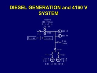
CASE STUDY – INDIAN BASIN UTILITY INTERCONNECTION   JAN.  2002
INDIAN BASIN GAS PLANT Marathon Oil Co. Gas Processing Plant Five Synchronous Generators Totaling 3.48MVA Gas Turbine and Diesel Driven Equipment No Export Agreement with Utility
INTERCONNECTION BENEFITS Utility Provides a Source Instantaneous Energy when needed, Increasing Plant Electrical Reliability Plant Operating Costs are Reduced by Using Fuels from Process On-Site Generation can Maintain Critical Operations when Utility source is Unavailable, Creating Electrical Supply Redundancy
CASE STUDY CONTENT Utility Interconnection and Interconnection Protection and Control Directional Overcurrent Protection Improves Plant Protection Selectivity Techniques used to Monitor Protection Quality Logical Next Steps and Conclusions
PLANT ELECTRICAL SYSTEM LAYOUT
UTILITY SOURCE AND POINT OF COMMON COUPLING (PCC) PCC resides at the low side of the 12470 – 480vac 1000 kva transformer  1600 A, 480 V Circuit Breaker #352 Interconnect breaker 480 V Plant Bus Feeds Critical Plant Loads
INTERCONNECTION EQUIPMENT PCC resides at the low side of the 12470 – 480vac 1000 kva transformer 1600 A, 480 V Circuit Breaker #352 Interconnect breaker to Plant 480 V Bus 480 V Plant Bus Feeds Critical Plant Loads
GAS TURBINE GENERATION AND CRITICAL PLANT LOADS  Three 800Kw 0.8 Power Factor Generators Feed the Plant 480 V Bus Automatic Load and Var Controls  The Plant Electrical System is Predominantly High Resistance Grounded 480 V Plant Bus Feeds Critical Motor Control Centers, Process Loads and Building Loads
DIESEL GENERATION and 4160 V SYSTEM
DIESEL GENERATION and 4160 V PLANT LOADS  Two 540Kw 0.8 Power Factor Generators Feed the Plant 4160 V System Fixed Load and Voltage Regulations Controls  The 4160 V Plant Electrical System is Predominantly High Resistance Grounded 4160 V System Feeds Two Large Motors and Small Process Loads.
ELECTRICAL SYSTEM TIE EQUIPMENT 480 – 4160 V 1500 kva Transformer Connects the 480 V and 4160 V Systems  1600 A, 480 V Circuit Breaker #552 Tie breaker 4160 V Plant Bus Feeds Large Motor Loads
UTILITY SOURCE TRANSFORMER CONNECTION Utility Advantages of the Ground Wye High Side Configuration Utility distribution system remains solidly grounded even if plant generation feeds the distribution circuit Utility Advantages of the Delta Low Side Configuration Zero Sequence Isolation, no ground fault contribution from plant generation
UTILITY SOURCE TRANSFORMER CONNECTION Plant Advantages of Grounded Wye High Side Configuration Plant generation does cause utility distribution circuit arrestor damage during short periods of back feed Plant Advantages of Delta Low Side Configuration Zero sequence isolation, plant can operate with a High Resistance Grounded (HRG) system
DISTRIBUTION CIRCUIT ARRESTOR OVER VOLTAGE
UTILITY INTERCONNECTION PROTECTION The SEL-351 Multifunction Microprocessor Relay Protection and control Event and sequential event reports Programmable display messaging Failsafe Alarm Contact Provides System Status
VOLTAGE PROTECTION ELEMENTS Single Level Over Voltage and Under Voltage Protection Under voltage protection set at 94% of nominal with 120 cycle delay Over voltage protection set at 132% of nominal with 120 cycle delay System Utilizes Open Delta Connected Potentials
FREQUENCY PROTECTION ELEMENTS Single Level Definite Time Over and Under Frequency Protection Under frequency set at 59.25 Hz with five cycle delay Over frequency set at 60.25 Hz with five cycle delay Under Voltage Frequency Disable Set at 40 V
ISLANDING PROTECTION ELEMENT Load Encroachment Element Detects load flow to the utility via positive sequence impedance calculations Detects three-phase reverse power flow as small as 125 Kw Reverse power time delay of four seconds allows plant generation control time to compensate after a load shed occurs
LOAD ENCROACHMENT ELEMENT
RECOMMENDED ENHANCEMENTS Inadvertent Energization of the Utility Distribution System Programmable close interlock contact to prevent #352 interconnect breaker closing if distribution system is de-energized Use SEL-351 check synch element as an additional layer for out of synch close protection
UTILITY VOLTAGE NORMAL
UTILTIY FREQUENCY NORMAL
CLOSE CIRCUIT CONTROL
PROTECTION SYSTEM MONITORING Utilize Loss of Potential Indication to Operate Protection System Abnormal Alarm Contact Control Protection Element Operation with Loss of Potential Status if Interconnection is Critical
PLANT DISTRIBUTION 480-4160V TIE PROTECTION SEL-351 Multi-Function Microprocessor Relay Provide Fast Low Set Overcurrent Protection  Not sensitive to loading  Secure for disturbances on the utility feeder Additional Overcurrent Protection for Balanced Fault Conditions Less sensitive and secure during motor starting operations on the 4160 vac system
FAST LOW SET PROTECTION Definite Time Directional Negative Sequence Element Operates for unbalance faults on the 4160V system Two cycle definite time delay avoids tripping on negative sequence transients
BALANCED FAULT PROTECTION Set Above Load and Motor Starting Inrush High set non-directional definite time overcurrent Non-directional extremely inverse time over current element This Combination Operates During Balanced Fault Conditions and is Secure During Motor Starting Inrush
ADVANTAGES OF TIE PROTECTION SYSTEM Closed Tie Continuity For unbalanced disturbances on the utility distribution system For motor starting operations on the 4160V system Fast Clearing of Unbalanced Faults on the 4160V System Minimizes Effects to the 480V Plant Bus
RECOMMENDED ENHANCEMENTS TO TIE PROTECTION Use SEL-351 check synch element as an additional layer for out of synch close protection Utilize Loss of Potential Indication to Operate Protection System Abnormal Alarm Contact Control Protection Element Operation with Loss of Potential Status
PROTECTION QUALITY MEASUREMENTS Sequential Event Reports Time tagged protection system element status report Unused levels of over current protection used for monitoring via sequential event reports Unused levels of over current protection are not programmed for tripping
EVENT ANALYSIS Event Reports Capture System Disturbances Provide greater detail with pre and post fault data  Graphical representations of voltage and current waveforms along with frequency magnitudes Protection system element status time synchronized with voltage and current waveforms Phasor plots of voltage current and sequence quantities
EVENT REPORT WAVEFROM GRAPHIICS
PHASOR PLOT GRAPHICS
DISPLAY MESSAGING Protection System Display Messaging Add descriptive text into rotating display based on protection element status Enhances protection system targeting Provides additional information to operating personnel
CONCLUSIONS Multi-functional Microprocessor Relays are Well Suited for Interconnection Protection Interconnection Protection  Over and Under Frequency Elements Over and Under Voltage Elements Non-Islanding Protection Close Interlock Control Monitor Protection System Performance

Uploaded

  • 1.
    CASE STUDY –INDIAN BASIN UTILITY INTERCONNECTION JAN. 2002
  • 2.
    INDIAN BASIN GASPLANT Marathon Oil Co. Gas Processing Plant Five Synchronous Generators Totaling 3.48MVA Gas Turbine and Diesel Driven Equipment No Export Agreement with Utility
  • 3.
    INTERCONNECTION BENEFITS UtilityProvides a Source Instantaneous Energy when needed, Increasing Plant Electrical Reliability Plant Operating Costs are Reduced by Using Fuels from Process On-Site Generation can Maintain Critical Operations when Utility source is Unavailable, Creating Electrical Supply Redundancy
  • 4.
    CASE STUDY CONTENTUtility Interconnection and Interconnection Protection and Control Directional Overcurrent Protection Improves Plant Protection Selectivity Techniques used to Monitor Protection Quality Logical Next Steps and Conclusions
  • 5.
  • 6.
    UTILITY SOURCE ANDPOINT OF COMMON COUPLING (PCC) PCC resides at the low side of the 12470 – 480vac 1000 kva transformer 1600 A, 480 V Circuit Breaker #352 Interconnect breaker 480 V Plant Bus Feeds Critical Plant Loads
  • 7.
    INTERCONNECTION EQUIPMENT PCCresides at the low side of the 12470 – 480vac 1000 kva transformer 1600 A, 480 V Circuit Breaker #352 Interconnect breaker to Plant 480 V Bus 480 V Plant Bus Feeds Critical Plant Loads
  • 8.
    GAS TURBINE GENERATIONAND CRITICAL PLANT LOADS Three 800Kw 0.8 Power Factor Generators Feed the Plant 480 V Bus Automatic Load and Var Controls The Plant Electrical System is Predominantly High Resistance Grounded 480 V Plant Bus Feeds Critical Motor Control Centers, Process Loads and Building Loads
  • 9.
    DIESEL GENERATION and4160 V SYSTEM
  • 10.
    DIESEL GENERATION and4160 V PLANT LOADS Two 540Kw 0.8 Power Factor Generators Feed the Plant 4160 V System Fixed Load and Voltage Regulations Controls The 4160 V Plant Electrical System is Predominantly High Resistance Grounded 4160 V System Feeds Two Large Motors and Small Process Loads.
  • 11.
    ELECTRICAL SYSTEM TIEEQUIPMENT 480 – 4160 V 1500 kva Transformer Connects the 480 V and 4160 V Systems 1600 A, 480 V Circuit Breaker #552 Tie breaker 4160 V Plant Bus Feeds Large Motor Loads
  • 12.
    UTILITY SOURCE TRANSFORMERCONNECTION Utility Advantages of the Ground Wye High Side Configuration Utility distribution system remains solidly grounded even if plant generation feeds the distribution circuit Utility Advantages of the Delta Low Side Configuration Zero Sequence Isolation, no ground fault contribution from plant generation
  • 13.
    UTILITY SOURCE TRANSFORMERCONNECTION Plant Advantages of Grounded Wye High Side Configuration Plant generation does cause utility distribution circuit arrestor damage during short periods of back feed Plant Advantages of Delta Low Side Configuration Zero sequence isolation, plant can operate with a High Resistance Grounded (HRG) system
  • 14.
  • 15.
    UTILITY INTERCONNECTION PROTECTIONThe SEL-351 Multifunction Microprocessor Relay Protection and control Event and sequential event reports Programmable display messaging Failsafe Alarm Contact Provides System Status
  • 16.
    VOLTAGE PROTECTION ELEMENTSSingle Level Over Voltage and Under Voltage Protection Under voltage protection set at 94% of nominal with 120 cycle delay Over voltage protection set at 132% of nominal with 120 cycle delay System Utilizes Open Delta Connected Potentials
  • 17.
    FREQUENCY PROTECTION ELEMENTSSingle Level Definite Time Over and Under Frequency Protection Under frequency set at 59.25 Hz with five cycle delay Over frequency set at 60.25 Hz with five cycle delay Under Voltage Frequency Disable Set at 40 V
  • 18.
    ISLANDING PROTECTION ELEMENTLoad Encroachment Element Detects load flow to the utility via positive sequence impedance calculations Detects three-phase reverse power flow as small as 125 Kw Reverse power time delay of four seconds allows plant generation control time to compensate after a load shed occurs
  • 19.
  • 20.
    RECOMMENDED ENHANCEMENTS InadvertentEnergization of the Utility Distribution System Programmable close interlock contact to prevent #352 interconnect breaker closing if distribution system is de-energized Use SEL-351 check synch element as an additional layer for out of synch close protection
  • 21.
  • 22.
  • 23.
  • 24.
    PROTECTION SYSTEM MONITORINGUtilize Loss of Potential Indication to Operate Protection System Abnormal Alarm Contact Control Protection Element Operation with Loss of Potential Status if Interconnection is Critical
  • 25.
    PLANT DISTRIBUTION 480-4160VTIE PROTECTION SEL-351 Multi-Function Microprocessor Relay Provide Fast Low Set Overcurrent Protection Not sensitive to loading Secure for disturbances on the utility feeder Additional Overcurrent Protection for Balanced Fault Conditions Less sensitive and secure during motor starting operations on the 4160 vac system
  • 26.
    FAST LOW SETPROTECTION Definite Time Directional Negative Sequence Element Operates for unbalance faults on the 4160V system Two cycle definite time delay avoids tripping on negative sequence transients
  • 27.
    BALANCED FAULT PROTECTIONSet Above Load and Motor Starting Inrush High set non-directional definite time overcurrent Non-directional extremely inverse time over current element This Combination Operates During Balanced Fault Conditions and is Secure During Motor Starting Inrush
  • 28.
    ADVANTAGES OF TIEPROTECTION SYSTEM Closed Tie Continuity For unbalanced disturbances on the utility distribution system For motor starting operations on the 4160V system Fast Clearing of Unbalanced Faults on the 4160V System Minimizes Effects to the 480V Plant Bus
  • 29.
    RECOMMENDED ENHANCEMENTS TOTIE PROTECTION Use SEL-351 check synch element as an additional layer for out of synch close protection Utilize Loss of Potential Indication to Operate Protection System Abnormal Alarm Contact Control Protection Element Operation with Loss of Potential Status
  • 30.
    PROTECTION QUALITY MEASUREMENTSSequential Event Reports Time tagged protection system element status report Unused levels of over current protection used for monitoring via sequential event reports Unused levels of over current protection are not programmed for tripping
  • 31.
    EVENT ANALYSIS EventReports Capture System Disturbances Provide greater detail with pre and post fault data Graphical representations of voltage and current waveforms along with frequency magnitudes Protection system element status time synchronized with voltage and current waveforms Phasor plots of voltage current and sequence quantities
  • 32.
  • 33.
  • 34.
    DISPLAY MESSAGING ProtectionSystem Display Messaging Add descriptive text into rotating display based on protection element status Enhances protection system targeting Provides additional information to operating personnel
  • 35.
    CONCLUSIONS Multi-functional MicroprocessorRelays are Well Suited for Interconnection Protection Interconnection Protection Over and Under Frequency Elements Over and Under Voltage Elements Non-Islanding Protection Close Interlock Control Monitor Protection System Performance