SlideShare a Scribd company logo
1 of 153
UNIT IV WIND ENERGY
• Sources and potentials, horizontal and vertical axis
windmills, performance characteristics, Betz criteria
BIO-MASS: Principles of Bio-Conversion,
Anaerobic/aerobic digestion, types of Bio-gas
digesters, gas yield, combustion characteristics of bio-
gas, utilization for cooking, I.C.Engine operation and
economic aspects.
INTRODUCTION TO WIND ENERGY
• Wind energy is an indirect form of solar energy.
• The uneven Earth's terrains get unequally heated by the sun rays. It makes
some regions of the earth warmer than others.
• The hot air in the warmer regions becomes less dense and light and thus it
rises up.
• This upward movement of hot air creates a vacuum which is immediately
filled up by cold air from the adjacent cooler realms.
• Wind power is the conversion of wind energy into a useful form of energy
such as using Wind turbines to make electricity, windmills for mechanical
power, wind pumps for water pumping or drainage or sails to propel ships.
Source or Origin of Wind
• Wind is produced by the uneven heating of the Earth's surface.
• The poles of the Earth receive less energy from the Sun than the equator.
Among these twos the dry land heats up (and cools down) more quickly than
sea.
• The Earth's surface is made of different types of land and water, it absorbs sun'
radiant energy at different rates.
• The non uniform thermal effects combine with the dynamic effects from the
Earth's rotation that produce prevailing wind patterns.
• There are also minor changes in the flow of the air as result of the differential
heating of sea and land.
• The nature of terrain ranging from mountain and valleys to more local obstacles
such as buildings and trees also has an important effect of the origin of wind.
Characteristics of Wind Energy
• Wind-power systems do not pollute the atmosphere.
• Fuel provision and transport are not required in wind-
power systems.
• Wind energy is a renewable source of energy.
• competitive With conventional power generating
system when produced on a large scale.
Wind Speed
• Power in the wind is proportional to the cube of the wind speed.
• It is well known that the highest wind velocities are generally found on
hill tops, exposed coasts and out at sea.
• various parameters like the mean wind speed directional data and
variations about the mean in the short-term (drafts), daily, seasonal and
annual variations as well as variations with height.
• These parameters are highly site specific and they can only be
determined with sufficient accuracy by measurements at a particular site
over a sufficiently long period.
• General meteorological statistics may overestimate the wind speed at a
specific site.
• To calculate the amount of electricity that can be produced by wind
turbines in a certain region.
Wind Data
• The wind is measured on the basis of many factors such as time availability, budget
allocated for the measurement and accuracy needed for the estimation.
• It is better to use metrological data/or civil aviation data. Basically, the measurements
are wind speed and wind direction.
• The standardized wind data should be used similar to a metrological department.
• The metrological department collects data continuously about wind from many
airports and data from anemometers located at 10 m height in order to follow the world
standard.
• But the height of the hub in a wind turbine is generally kept at more than 10 m. In that
condition, the variations in speed of the wind with height are to be incorporated for
predicting the energy available in the wind.
• Sometimes, anemometers provide inaccurate data due to the friction in bearings
rotating slowly.
Beaufort scale
• The Beaufort scale is a scale for measuring wind
speeds.
• It is based on observation rather than accurate
measurement.
• It is the most widely used system to measure wind
speed today.
• The scale was developed in 1805 by Francis
Beaufort, an officer of the Royal Navy and first
officially used by HMS Beagle.
• A wind farm or wind park, also called a wind power
station or wind power plant, is a group of wind
turbines in the same location used to produce
electricity
WIND ENERGY POTENTIAL
• The power available in the wind over the earth surface is estimated to be
1.6x10^7MW which is more than the present energy requirement of the world.
• The installation cost of wind power is Rs. 4 crore / MW which is almost same
of conventional thermal power plants.
• Asia was the largest regional market for the ninth consecutive year,
representing nearly 48% of added capacity (with a total exceeding 235 GW by
the end of year 2017), 30 countries had more than 1 GW in operation.
• There has been remarkable growth of wind power installation in the world.
• China leads the world in terms of total installed wind capacity (188.4 GW)
and followed by the US (89 GW), Germany (56.1 GW), India (32.8 GW),
Spain (20 GW), the UK (18.9 GW) and France (13.8 GW) at the end of 2017.
Wind energy potential in India
• The development of wind power in India began in the 1986 with first wind
farms being se up in coastal areas of Maharashtra (Ratnagiri), Gujarat (Okha)
and Tamil Nadu (Tuticorin) with 55 kW Vestas wind turbines.
• The capacity has significantly increased in the last few years.
• A total capacity of 32.85 GW has been established upto December, 2017.
• The wind power projects in India are mainly spread across south, west and
north regions while east and north-east regions have no grid connected wind
power plant.
• Wind power generation in India is highly influenced by the monsoon in India.
• The strong south-west monsoon, starts in May-June, when cool, humid air
moves towards the land and the weaker north-east monsoon, starts in
October, when cool dry air moves towards the ocean.
• During the period of March to August, the winds are uniform and strong
over the Whole Indian peninsula, except the eastern peninsular coast.
• Wind speed during the period of November to March is relatively weak.
• Most of the capacity (7.97 GW) is installed in the state of Tamil Nadu in
India.
BASICS OF WIND ENERGY ELECTRICITY GENERATION
• Typical components of a wind turbine are gearbox, rotor shaft and brake
assembly being lifted into position.
• In a wind farm, individual turbines are interconnected with a medium
voltage (usually 34.5 kV) power collection system and communication
networks.
• At a substation, this medium-voltage electrical current is increased in
voltage with a transformer for the connection to high voltage electric power
transmission system.
• Wind turbine is a rotating machine which converts the kinetic energy of
wind into mechanical energy.
• If the mechanical energy is directly used by the machinery such as a pump or
grinding stones, the machine is usually called a windmill.
• If the mechanical energy is converted into electricity, the machine is called a
wind generator, wind turbine, Wind Power Unit (WPU), Wind Energy
Converter (WEC) or aero-generator.
Capacity Factor
Penetration
• Penetration Wind energy penetration is defined as the fraction of energy produced by wind from
the total available generation capacity.
• The penetration depends on the existing generating plants, pricing mechanisms, capacity for
storage or demand management and other factors.
Variability and Intermittency
• Electricity generated from wind power is highly variable at different time scales: from
hour to hour, daily and seasonally.
• Wind power forecasting methods are used but the predictability of wind plant output is
again less for short-term operation.
• Intermittency and non-dispatchable nature of wind energy production increase the cost for
regulation and incremental operating reserve.
• The variation in load and allowance for failure of large generating units require at low
level of wind penetration reserve capacity thereby regulating the variability of wind
generation.
• Hybrid wind power can be used during low wind period. Wind power can be replaced by
other power stations during low wind period.
ADVANTAGES OF WIND POWER
1. Wind power emits absolutely no greenhouse gases. Therefore, there is no pollution.
2. Wind is obtained at free of cost.
3. Wind power is helpful in supplying electricity to remote areas.
4. Wind energy itself is both renewable and sustainable. The wind will never run out.
5. The potential of wind power is enormous i.e. 20 times more than what the entire human
population needs.
6. Wind power generation is cost effective and reliable. Wind power is an ideal choice for
micro-generation.
7. Wind turbines are fairly low in maintenance.
8. As wind energy is free, running costs are often low
DISADVANTAGES OF WIND POWER
1. Wind is a fluctuating (intermittent) source of energy and it is not suited to meet
the base load energy demand.
2. Wind energy requires some form of energy storage e.g. batteries and pumped
hydro.
3. The manufacturing and installation of wind turbines require heavy upfront
investments.
4. Wind turbines can be a threat to wildlife (e.g. birds, bats).
5. Some wind turbines tend to generate a lot of noise which can be unpleasant.
6. Wind energy has low energy density but it is favourable in many geographical
locations from cities and forests.
7. Wind power can even affect the national security because wind farms cause
holes in RADAR coverage as the blades on turbines confuse the system.
APPLICATIONS OF WIND ENERGY
• Utility interconnected wind turbines generate power which is synchronous
with the grid and are used to reduce utility bills by displacing the utility
power used in the household and by selling the excess power back to the
electric company.
• Wind turbines for remote homes (off the grid) generate DC current for
battery charging.
• Wind turbines for remote water pumping generate 3 phase AC current
suitable for driving an electrical submersible pump directly.
• Wind turbines suitable for residential or village scale wind power range
from 500 W to 50 kW.
ESTIMATION OF WIND ENERGY
Overall conversion efficiency
• Overall conversion efficiency can also be given in another tern called power
coefficient (Cp).
• It is defined as the ratio of the output power produced to the power available in
the wind.
• The power coefficient is a function of both tip speed ratio and blade pitch
angle.
• The overall conversion efficiency of the machine is a function of the following
factors.
• Wind velocity
• Angular of velocity of rotor in the wind turbine
• Pitch angle
• Design of aerofoil section and
• Number of blades.
WIND POWER DENSITY
Derivation of Betz Criteria or Maximum Wind Power and Efficiency
Betz criteria or Betz Emit
• Betz criteria or Betz Emit is the theoretical limit assigned to efficiency of
a wind turbine.
• It states that no turbine can convert more than 59.3 % of wind kinetic
energy into mechanical energy.
• Thus, the value of power coefficient (CO is limited to Betz limit.
• For a well-designed turbine, the efficiency lies in the range of 35-45 %.
WIND ENERGY CONVERSION
• The wind energy can be extracted from lift force alone or combination
of lift and drag force.
• Lift force acts perpendicular to air flow direction.
• Drag force acts parallel to the wind direction.
• The lift is produced by the change in velocity of air stream which
speeds up the air flow thereby creating a pressure drop.
• So, the pressure drop forces the lift surface from high pressure side to
low pressure side of an aerofoil.
• If the air pressure increases on the low pressure side, enormous
turbulence is produced which reduces the lift force and it leads to
increase the drag significantly called stalling.
Aerodynamics of Wind Turbine
• In wind turbines, aerodynamics deals with the relative motion between moving
air and stationary aerofoil.
• The aerofoil is the cross section of the blade of the wind turbine.
• It is the shape designed to create maximum lift force when air flows over it.
• In the wind turbine, linear kinetic energy associated with the wind is converted
into the rotational motion that is required to turn the electrical generator for
power generation.
• This change is accomplished by a rotor that has one, two or three blades or
aerofoils attached to the hub.
• The wind flowing over the surfaces of these aerofoils generates the forces that
cause the motor to run.
• Wind passes more rapidly over the longer (upper) path of the aerofoil in
comparison to the shorter (lower) path.
• High and low pressure regions can be identified by using Bernoulli's equation.
• Therefore, low pressure is created in the upper surface of the aerofoil and high
pressure in its lower surface.
• The pressure difference between top and bottom surfaces of the aerofoil results
a force called aerodynamic lift as air moves from high-pressure region to low-
pressure region.
• The upward force due to aerodynamic lift pushes the blades to move up.
• Hence, in aerodynamic analysis of wind turbines, both lift and drag forces are
important for their optimisation in efficient design.
Components of wind turbines
Wind turbine or windmill
• A system of blades fixed on a tower is rotated by the wind to either produce
mechanical work or electrical energy.
• The wind turbine may be located either upwind or downwind of the power.
• In the upwind location, the wind encounters the turbine before reaching the
tower.
• Downwind machines have the rotor placed on the lee side of the tower.
• They have the theoretical advantage that they may be built without a yaw
mechanism
Nacelle
• It includes gearbox, low- and high-speed shafts, generator controller and
brake.
• It is placed at the top of the tower and it is connected to the rotor.
Rotor
• The hub and blades together compose the rotor. Most of the horizontal-axis
wind turbines use two or three blades in an upwind design.
• Blades are manufactured frog Fibreglass-Reinforced Polyester (FRP), wood
laminates, steel or aluminium.
• A FRP blade is comparatively lighter and it exerts less stress on bearing and
rotor hubs.
• Other manufacturers use steel blades because of the ease of fabrication, greater
strength and lower cost.
• Sometimes, wood laminates blades are also used due to their excellent fatigue
resistance properties.
• Vertical axis wind-turbine manufacturers often use extruded aluminium blades.
Hub and shaft
• Rotors of the wind turbine are attached with the shaft and hub assembly.
• The hub is front portion of the shaft which faces the wind direction.
• It is normally of conical shape.
• The other end of the shaft is attached to the transmission system of the
wind turbine.
Anemometer
• This device is used for the measurement of speed.
• The wind speed is also fed to the controller as it is one of the variables for
controlling pitch angle and yaw.
• Wind turbines are available in various sizes according to the potential 'to
generate electricity in ideal wind conditions. It is called "rated capacity.“
• Wind turbine capacity ratings range from 250 W to 1.65 MW. Electricity
production and consumption are referred in kilowatt-hours (kWh).
Robinson Cup Anemometer Proster Handheld
Anemometer
Transmission system
• The transmission system contains a gearbox, clutch and braking system to stop
the rotor in an emergency.
• The purpose of the gearbox is to increase the speed of the rotor typically from
20 rpm to 50 rpm or from 1000 rpm to 1500 rpm which is required for driving
the most types of electric generators.
• The transmission system must be designed for high dynamic torque loads due to
the fluctuating power output from the rotor
Electric generator
Major types of rotational electrical machines commonly used in a wind power
generating systems:
• The direct current ( DC ) machine, also known as a Dynamo
• The alternating current ( AC ) synchronous machine, also known as an AC
Generator
• The alternating current ( AC ) induction machine, also known as an
Alternator
Yaw control system
• It is used to continuously orient the rotor in the direction of the wind.
• The horizontal-axis wind turbine has a yaw control system that turns the
nacelle according to the actual wind direction using a rotary actuator attached
to the gear ring at the top of the wind tower.
• The wind direction must be perpendicular to the swept rotor area during
normal operation of the wind turbine.
• A slow closed-loop control system is used to control the yaw drives.
• A wind vane mounted on the top of the nacelle senses the relative wind
direction and the wind-turbine controller then operates the yaw drives.
Storage
• used to store energy when there is excess power developed and to discharge it
when there is a lack in power.
• The most common storage device is the lead-acid battery.
• If the wind energy conversion system is to pump water and the pumped
storage system of water is followed.
• Usually, the electricity produced from wind energy is Direct Current (DC).
• So, it should be converted into Alternating Current (AC) using an alternator
before supplying it to the transmission grid for industrial and household
appliances.
Energy converters
Towers
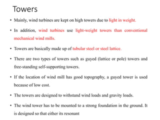
• Mainly, wind turbines are kept on high towers due to light in weight.
• In addition, wind turbines use light-weight towers than conventional
mechanical wind mills.
• Towers are basically made up of tubular steel or steel lattice.
• There are two types of towers such as guyed (lattice or pole) towers and
free-standing self-supporting towers.
• If the location of wind mill has good topography, a guyed tower is used
because of low cost.
• The towers are designed to withstand wind loads and gravity loads.
• The wind tower has to be mounted to a strong foundation in the ground. It
is designed so that either its resonant
Wind mill tower types
Usually, the range of tower is from 12 m to 37 m for small wind applications and it is from
30 m to 75 m or higher for moderate wind turbines.
TYPES OF WIND MILLS
• Based on the axis of rotation of the rotor, wind
turbines are further classified as follows:
• Horizontal-axis wind machines
• Vertical-axis wind machines.
Horizontal-axis wind machines
• In horizontal axis wind mills or turbines, the axis of
rotation is horizontal with respect to the ground.
• In this case, the rotating shaft is parallel to the ground
and the blades are perpendicular to the ground.
• Horizontal-axis or propeller-type turbines are more
common and highly developed than vertical-axis
turbines.
• We call the wind turbines that have horizontal shaft as horizontal axis wind turbines or in
short HAWT.
• In HAWT the turbine rotor couples the electrical generator and this turbine generator set is
placed on the top of the turbine tower.
• A wind sensor with servomotor keeps the axis of the turbine along the path of the wind.
• Although in small turbine a wind vane does the purpose.
• The turbines commonly have a gearbox in between the turbine shaft and the generator
shaft.
• The functions of this gearbox are to provide mechanical coupling between these two
shafts and to step up the slow rotating speed of the turbine blades to a high rotating speed
of the generator.
• A wind electric power generating station uses three blades horizontal axis
wind turbines (HAWT).
• Three blades design is more mechanically stable and can have less torque
ripple.
• The blade-length may be from 20 m to 80 m and usually of bright white
colored so that any aircraft can view comfortably.
• A turbine with the blade length of 80 m may have rating up to 8 MW.
• The height of the large commercial turbine may be up to 70 m to 120 m and
may be up to 160 meters in the extreme.
• The modern wind turbine systems use steel tubular supporting poles. The
RPM of a large wind turbine may be from 10 to 22.
• Although, there are some designs in which the turbine rotor shaft directly
couples the generator.
• No one can control the wind pressure on the blades by any means it entirely
depends on nature.
• The designers provide a protective system to all large wind turbine which
aligns the blade-edge faces depending on the speed of the wind so that we
can avoid breakage of the blades during high wind pressure. We call this
technique the feathering.
Advantages
• Variable blade pitch which give the turbine blades the optimum angle of attack.
• The tall tower base allows an access to stronger wind in sites with wind shear.
• Efficiency is high in receiving power through the whole rotation since the
blades always move perpendicularly to the wind.
• The face of a horizontal axis blade is struck by the wind at a consistent angle
regardless of the position in its rotation.
Disadvantages
• HAWTs have difficulty operating in near ground and turbulent winds. Therefore,
tall towers are required.
• The tall towers and blades up to 90 m long are difficult to transport.
• Tall HAWTs are difficult to install and they need very tall and expensive cranes and
skilled operators.
• Massive tower construction is required to support heavy blades, gearbox and
generator.
• Reflections on tall HAWTs may affect side lobes of radar installations creating
signal clutter although filtering can suppress it.
• Downwind variants suffer from fatigue and structural failure caused by turbulence
when a blade passes through the tower's wind shadow.
• HAWTs require an additional yaw control mechanism to turn the blades towards
wind.
Vertical-Axis Wind Turbines
• In Vertical-Axis Wind Turbines (or VAWTs), the main rotor shaft arranged
vertically and the axis of rotation is vertical with respect to the ground.
• The key advantage of this arrangement is that the turbine does not need to be
pointed into the wind streams to be effective because their operation is
independent of wind direction and these vertical axis machines are called
panemones.
• It is an advantage on sites where the wind direction is highly variable.
•
• With a vertical axis turbine, the generator and gearbox can be placed near the
ground so the tower does not need to support it and it is more accessible for
maintenance.
• Drawbacks are that some designs produce pulsating torque.
• It is difficult to mount vertical-axis turbines on towers because they are
often installed nor the base on which they rest such as the ground or a
building rooftop.
• The wind speed is slow at a lower altitude. So, less wind energy is available
for a given size of turbine.
• Air flow near the ground and other objects can create turbulent flow which
can introduce issues of vibration including noise and bearing wear which
may increase the maintenance or shorten the service life.
• However, when a turbine is mounted on a rooftop, the building generally
redirects wind over the roof and it can double the wind speed at the turbine.
•
• If the height of the rooftop mounted turbine tower is approximately 50% of
the building height, it is near the optimum point for maximum wind energy
and minimum wind turbulence.
Types of vertical-axis wind turbines
• 1. Darrieus rotor
• 2. Savonius rotor (turbo machine)
• 3. Multiple blade rotor
• 4. Musgrove rotor
• 5. Evans rotor.
Darrieus rotor
Darrieus rotor
• This rotator is shaped such as an egg beater and it consists of two or three
curved blades shaped such as aero foils.
• The driving forces are lifting forces. This wind mill needs much less surface
area.
• The maximum torque occurs when a blade is moving across the wind of a
speed much high than wind speed.
• Initial movement may be initiated with the electrical generator used as a
motor.
Savonius rotor (turbo machine)
Helical Savonius
Savonius rotor (turbo machine)
• This type of windmill has hollow circular cylinder sliced in half and the
halves are mounted on a vertical shaft with a gap in between them.
• There is a complicated motion of wind through and around the two curved
sheet aerofoils rotates by drag force.
• Torque is produced by the pressure difference between two sides of the half
facing the wind.
• It is quite efficient but it needs a large surface area.
• It is simple in construction and it is inexpensive.
Multiple blade rotor
• It is the most widely used type of wind mill.
• It has 15 to 20 blades made from metal sheets.
• The sail type has three blades made by stitching out triangular pieces of
canvas cloth.
• these types run at low speed of 60 rpm to 80 rpm.
Musgrove rotor
In this rotor, the blades are vertical for normal power generation. This rotor has an
advantage of fail-safe shut down in strong winds.
Evans rotor
• Vertical blades twist about a vertical axis speed for
control and a fail-safe shut down.
• Other types of wind mills available for the power
generation are: Four-blade Dutch wind !Dill and
propeller type.
• For water pumping and small-battery operation, it
is desirable to allow the rotor speed to vary.
Advantages
• A massive tower structure is less frequently used as VAWTs are more frequently
mounted with lower bearing mounted near the ground.
• Designs without yaw mechanisms are possible with fixed pitch rotor designs.
• The generator of a VAWT can be located near the ground making it easy to
maintain moving parts.
• VAWTs have lower wind startup speeds than HAWTs. Typically, they start to
generate electricity at 6 mph (10 km/h).
• VAWTs may be built at locations where tall structures are prohibited.
• VAWTs situated close to the ground can take the advantage of locations where I -
mesas, hilltops and ridgelines. They pass funnel the wind and increase the wind
velocity.
• VAWTs may have a lower noise signature.
Disadvantages
• A VAWT which uses guy-wires to hold it in place puts stress at the bottom
bearing as the whole weight of the rotor is on the bearing.
• The stress in each blade due to wind loading changes its sign twice during
each revolution as the apparent wind direction moves through 360°. This
reversal of the stress increases the chance of failure by fatigue.
• While VAWTs' parts are located on the ground, they are also located under
the weight of the structure above it which can make changing of parts
nearly impossible without dismantling the structure if it is not designed
properly.
• Having rotors located close to the ground where wind speed is low due to
the ground's surface drag, VAWTs may not produce as much energy at a
given site as a HAWT with the same footprint or height.
PERFORMANCE CHARACTERISTICS
OF WIND TURBINE ROTORS
• Solidity
• Tip-speed ratio
• Performance coefficient
• Torque
• Rotor Power control
• Solidity - Solidity is defined as the percentage of circumference of the rotor which
contains the material instead of air.
Solidity is calculated by Percentage of solidity = 31.8 x Number of blades x
Blade width x Rotor diameter
• Tip-speed ratio - It is defined as the ratio of speed of the blade tip of a windmill
rotor to the speed of free wind.
Tip-speed ratio = 0.052 x Rotor diameter x Rotation speed x Wind Speed
• Performance coefficient -
• Torque - It is the turning moment produced by the rotor.
1. It does mainly depend on solidity and tip speed ratio of the rotor.
2. Usually, the rotors with high solidity and low tip-speed ratio produce
more torque than rotors with low solidity and high tip-speed ratio.
3. At the same time, high speed machines produce maximum performance
coefficient but they have low starting torque.
•Rotor prime control
•There are two options for constant speed machines.
(i) Stall-regulated wind turbines: The pitch angle distribution along the blades
is constant for all wind speeds. At high wind speed STALL occurs.
(i) Pitch-regulated wind turbines: The blades can be rotated about their radial
axis during operation as the wind speed changes. It is therefore possible to
have an optimum pitch angle at all wind speed and a relatively low cut-in
wind velocity.
PERFORMANCE CHARACTERISTICS
OF WINDMILL
The following are the four important
characteristics of the wind speeds.
1. Cut-in wind speed
2. Design wind speed
3. Rated wind speed
4. Cut-out wind speed
(a) Cut-in wind speed: It is the wind speed when the machine begins to produce
power. It is typically between 3 m/s and 4 nt/s (10 km/hr and 14 km/hr, 7 mph and
9 mph).
(b) Design wind speed: It is the wind speed when the windmill reaches its
maximum efficiency.
(c) Rated wind speed: It is also called nameplate capacity. It is the wind speed
when the machine reaches its maximum output power. The rated wind speed is
typically about 15 m/s (54 km/hr, 34 mph) which is about double the expected
average speed of the wind.
(d) cut-out wind speed: It is the maximum safe working wind speed and the speed
at which the wind turbine is designed to be shut down by applying brakes to
prevent damage to the system.
• In addition to electrical or mechanical brakes, the turbine may be slowed down by
stalling or furling.
(i) Stalling: It is a self-correcting or passive strategy which can be used
with fixed speed wind turbines. As the wind speed increases, the wind
angle of attack is increased until it reaches its stalling angle at which
point the "lift" force turning the blade is destroyed.
(ii) Furling or feathering: It is a technique derived from sailing in which
the pitch control of the blades is used to decrease the angle of attack
which in turn reduces the "lift" on blades as well as the effective cross
section of the aerofoil facing into the wind.
• Survival wind speed:
This is the maximum wind speed that a given wind turbine is
designed to withstand above which it cannot survive. The survival speed of
commercial wind turbines is in the range of 50 m/s (180 km/hr, 112 mph) to
72 m/s (259 km/hr, 161 mph). The most common survival speed is 60 m/s
(216 km/hr, 134 mph).
TYPES OF WIND POWER PLANTS
• Remote or Off-grid wind power plants
• Small scale or Stand-alone wind turbines plants
• Medium scale wind turbine plants:
1. Single mode distribution
2. Multiple mode distribution
• Hybrid wind power plants
• Grid connected wind power plants
• Wind forms
SITE SELECTION FOR WIND ENERGY
SYSTEMS
(i) Plane site
(ii) Hill top site
(iii) Sea-shore site
(iv) Off-shore shallow water site.
Apart from the location selection, some other factors need to be considered such as technical,
environmental, social, economic and other factors.
The main considerations for selecting a site for wind turbine
installation are as follows:
1. Wind farms are located away from main cities to avoid resistance to the air
movement created by buildings. So, the flat area is advisable to locate wind
mill.
2. The basic requirement for a successful use of a windmill is an adequate supply
of wind speed.
3. The selected site should provide good average of wind velocity throughout the
year for continuous generation of energy.
4. The proposed site should be checked for high altitude due to strong winds which
will increase the electric power output of wind energy conversion system.
5. A stable ground is selected.
6. Small trees and grass are avoided under wind mill in order to minimise the
installation cost because the height of tower needs to be increased in such case.
7. The selected site should be easily accessible to provide a transport facility for the
erection of equipment and structures as well as for maintenance.
8. The site should be near the consumer for reducing the cost and transmission losses
of the generated power.
9. The land cost should be favourable so that the total project cost is minimal.
10. Wind direction is also considered for the site selection.
11. Topography such as mountain gap helps to channelise and speed up winds.
12. The selection of coastal area or lake area for wind mill installation is favourable
because differential heating of water and land generates wind of sufficient speed. The
wind blow from the land to the sea during day time and it is reversed during night
time.
Bio mass
• Biomass is organic matter produced by
plants, both terrestrial (those grown on
land) and aquatic (those grown in water)
and their derivatives.
• It includes forest crops and residues,
crops grown especially for their energy
content on “energy farms” and animal
manure.
• Biomass can be considered a renewable
energy source because plants life renews
and adds to itself every year.
• It can also be considered a form of solar
energy as the latter is used indirectly to
grow these plants by photosynthesis.
Bio mass resource
• The resources of biomass falls in
to three categories.
(i) Biomass in its traditional solid
mass (wood and agriculture
residue)
(ii) Biomass in non-traditional
solid form (converted into
liquid fuels)
• The first category is to burn
the biomass directly and get
the energy.
• In the second category, the
biomass is converted into
ethanol (ethyl alcohol) and
methanol (methyl-alcohol) to be
used as liquid fuels in engines.
Dr.N.Shankar Ganesh
•The third category is to
ferment the biomass
anaerobically to obtain a
gaseous fuel called bio-
gas.
Biomass includes wood waste
and bagasse (சர்க்கரை உற்பத்தியில்
உண்டாகும் கழிவு பபாருள்),
which have potential of generating
substantial electric power.
All these biomass are highly
dispersed and bulky and contain
large amounts of water (50 to 90
per cent).
Thus it is not economical to
transport them over long
distances.
However, biomass can be converted
to liquid or gaseous fuels, thereby
increasing its energy density and
making feasible transportation over
long distances.
Bio mass resource (contd.,)
Bagasse
Terrestrial crops include
i. Sugar crops such as sugarcane and
sweet sorghum
ii. Herbaceous crops which are non-
woody plants that are easily converted
into liquid or gaseous fuels.
iii. Silviculture (forestry) plants such as
cultured hybrid poplar, sycamore, sweet
gum, alder, eucalyptus, and other hard
woods.
Bio mass resource (contd.,)
Animal and human waste are indirect
crops from which the methane for
combustion and ethylene can be
produced while retaining the fertilizer
value of the manure.
Aquatic crops are grown in fresh sea and
brakish waters.
Terrestrial crops
Herbaceous crops
Bio - fuels
The energy stored in dry biomass like
wood and straw is most easily released
by direct combustion – although dry
materials can also be converted into
liquid and gaseous fuels (for later
combustion) by a variety of techniques.
Biomass that is wet or has a moisture
content like sewage sludge and
vegetable matter can be dried and burnt.
However, it requires considerable
energy to drive off the water, and this
diminishes the value of the biomass as
fuel.
Sewage sludge
Various Bio – fuels:
Solids – wood
straw
Municipal refuse
Liquids – Methanol and Ethanol
Alcohols
Vegetable oils
Gases - biogas
methane
fuel gas
BIOMASS ENERGY
• The energy obtained from organic matter derived from biological organisms
(plants and animals) is known as biomass energy or simply, bioenergy.
• Biomass resources are mainly classified into two categories. They are as
follows:
1. Biomass from cultivated fields, crops and forests.
2. Biomass from municipal waste, animal dung, forest waste, agricultural waste,
bioprocess waste and fishery waste.
• energy may be transformed either by chemical or biological.
• Biomass cycle maintains the environmental balance of oxygen, CO2, rain etc.
• Biomass is used for producing the process heat and electricity, gaseous and
solid fuels, liquid and chemicals.
Biomass Resources
• Forests - wood, charcoal, eucalyptus, pine
• Agricultural residues - straw, rice husk, coconut shell, groundnut shell,
sugarcane baggage
• Energy crops - cultivated plants produce raw material for bio-fuels. Eg:
sugarcane, oil plants
• Aquatic plants - plants grow very fast, seaweed and algae
• Urban waste: Urban waste is of two types. They are given below. (a)
Municipal solid waste (MSW) (b) Sewage (liquid waste).
Advantages of bio energy
• It is a renewable source.
• The pollutant emissions from combustion of biomass are usually lesser than
fossil fuels.
• Commercial use of biomass may avoid or reduce the problems of waste
disposal in other industries.
• Use of biogas plants apart from supplying clean gas also leads to improved and
stabilized sanitation.
• The forestry and agricultural industries which supply feed stocks also provide
substantial economic development opportunities in rural areas.
• The energy storage is an in-built feature of it.
Disadvantages of bio energy
• It is dispersed and land intensive source.
• It is often of low energy density.
• It is also labour intensive and the cost of collecting large quantities of
biomass for commercial application is significant.
• More space area.
• Source not available continuously
Applications of Bio Energy
• Biomass is an important source of energy and the most important fuel
worldwide after coal, oil and natural gas.
• Bio-energy in the form of biogas which is derived from biomass.
• Biomass offers higher energy efficiency through form of biogas than by
direct burning.
• Some of the potential applications of bio energy are: cooking, mechanical
applications, pumping and power generation.
• Biomass gasifiers convert the solid biomass (basically wood waste,
agricultural residues etc.) into a combustible gas mixture normally called
producer gas.
Applications of Bio Energy
• Water pumping and electricity generation. - to operate a diesel engine
• Heat generation. - for drying tea, flower, spices, kilns for baking tiles or
potteries, furnaces for melting non-ferrous metals, boilers for process
steam, etc
• High efficiency wood burning stoves.
• Bio fuels - Biodiesel can also be made by combining alcohol with
vegetable oil or recycled cooking greases.
BIOMASS FUELS
• Biomass is an organic carbon based material that reacts with oxygen in
combustion and natural metabolic process to release heat.
• Some of its forms available to users are given below.
1. Fuel wood
2. Charcoal
3. Fuel pellets
4. Bio-ethanol
5. Bio gas
6. Producer gas
7. Vegetable oils (bio-diesel).
• (i) Fuel wood: oldest source, combustion efficiency 16-20 MJ/kg. more useful
forms such as charcoal or producer gas.
• (ii) Charcoal: Charcoal is a clean, dry, solid fuel of black colour. It has 75-80%
carbon content and has 1 energy density of about 30 MJ/kg. It is obtained by
carbonization process of woody biomass, to achieve higher energy density per
unit mass. It is also used for making high quality steel.
• (iii) Fuel pellets: Crop residues such as straw, rice husk, cow dung-etc., are
pressed to form lumps known 1 as fuel pellets and used as solid fuel.
• (iv) Bio-ethanol: Ethanol (C21-150H) is a colourless liquid biofuel. Itsboiling
point is 78°C and energy density is 26.9 MJ/kg. It can be derived from wet
biomass containing sugar starches or cellulose. Commercial ethanol is used in
specially designed ICengines.
• (v) Biogas: Organic wastes from plants, animals and humans contain enough
energy to contribute significantly to energy supply in many areas. Biogas is
produced in a biogas fermenter. It is used for cooking, lighting, heating and
operating small IC engines, etc.
• (vi) Producer gas: Woody matter such as crop residue, wood chips, bagasse,
rice husk, coconut shell etc., can be transformed to producer gas (wood gas,
water gas or blue gas) by a method known as gasification of solid fuel.
• (vii) Vegetable oils (bio-diesel): It can be used as such or blended with diesel
as a diesel engine fuel.
PRINCIPLES OF BIO-CONVERSION
• Bioconversion, also known as biotransformation, is defined as
the process of conversion of organic materials such as plant or animal
waste into usable products or energy sources by biological processes or
agents such as certain microorganisms.
• Photosynthesis Definition: In simpler terms, the process of
photosynthesis is used by plants and other organisms to convert the
radiant energy/light energy into chemical energy, that can be used to
perform daily tasks.
Photosynthesis Process
• Biomass energy is obtained by photosynthesis process. It means the
synthesis process with light.
• Photosynthesis converts solar energy into biomass energy. It consists in
building up of simple carbohydrates such as sugar in the green leaf in the
presence of sunlight.
• Solar radiation incident on green plants and other photosynthesis organisms
perform two basic functions.
1. Temperature control for chemical reactions to proceed and
2. Photosynthesis process.
• It is the process of combining CO2, water and light energy to produce
oxygen and carbohydrates (sugar, starches, celluloses and hemicelluloses).
Photosynthesis Process
Necessary conditions for photosynthesis process
1. Light: It is one of the important input for biomass production.
2. CO2 concentration: It is the primary raw material for photosynthesis.
3. Temperature: Photosynthesis is restricted to the temperature range 0°C to
60°C.
BIOMASS CONVERSION PROCESSES
Broadly divided into four categories.
1. Physical process
2. Agrochemical process
3. Thermochemical processes
a) Direct combustion
b) Carbonisation
c) Pyrolysis
d) Gasification
e) Liquefication
4. Biochemical process
a) Anaerobic digestion
b) b) Ethanol fermentation.
Physical Conversion of Biomass
• The simplest method of physical conversion of biomass is through the
compression of combustible material.
• It is densified by compression through the processes called briquetting and
pelletisation.
• Briquetting is brought about by compression baling. Densification is carried out
by compression under a die. Briquettes (66 mm diameter and 96 mm thick) made
from paddy husk or sawdust is a cheap and effective fuel for the tobacco-curing
industry.
• Pelletisation is a process in which wood is compressed and extracted in the form
of rods (5-12 mm diameter and 12 mm long).
• It has applications in steam power plants and gasification systems.
• The purpose of pelletisation is to reduce the moisture contents and increase the
energy density of wood for longer transportation haulage.
Agrochemical Conversion of
Biomass
• production of fuels from plants.
• Generally, liquid or solid fuels may be obtained directly from living or freshly
cut plants.
• The materials are called exudates. obtained by cutting into stems and trunks
of the living plant or by crushing freshly harvested material.
• The oil of the plant itself can directly be used as an energy source.
• Categories of suitable materials are as follows: (i) Seeds (sunflower with 50%
oil) (ii) Nuts (oil palm; coconut copra to 50% by mass of oil) (iii) Fruits
(olive) (iv) Leaves (eucalyptus with 25% oil) (v) Tapped exudates (rubber
latex) (vi) Harvested plants
Thermochemical Process
(1) Direct Combustion
• oldest form of combustion.
• It is burnt to provide heat for cooking, comfort heat (space heat), crop drying,
factory processes and forming steam for electricity production and transport.
(2) Carbonization
• Carbonization is a process in which a fuel is heated without air to leave solid
porous carbon.
• Carbonization is the term which means destructive distillation of coal which is
done in the absence air in order to obtain coke and other fractions having
greater percentage of carbon than the original material
• Done by four stages by increasing their temperature to remove volatile
substance.
Carbonization
STAGES OF CARBONIZATION
1.At 20 to 110°C
The wood absorbs heat as it is dried giving off the moisture as water
vapour.
2.At 110 to 270°C
The final traces of the water are given off and the wood starts to
decompose by giving off carbon monoxide, carbon dioxide, acetic acid,
methanol etc.
3. At 270 to 290°C
This is the point at which the exothermic decomposition takes place.
4.At 290 to 400°C
As the breakdown of the wood continues the vapours given off consists of
the combustible gases like carbon monoxide,hydrogen,methane along with
carbon dioxide..
5.At 400 t0 500°C
The transformation of the wood to charcoal is completed.
Pyrolysis
3) Pyrolysis
Dry Process
Pyrolysis
The biomass can be converted into more
valuable and convenient fuels by the
use of the thermochemical process
called pyrolysis.
The Pyrolysis process is carried out by
heating the biomass in absence of air (or
oxygen) or by partial combustion of
some portion of the biomass in
restricted presence of air (or oxygen).
If pyrolysis is carried out at higher
temperature (above 1000 ºC), maximum
amount of gaseous product is formed.
This high temperature pyrolysis is
called gasification.
Biomass conversion technologies (Contd.,)
Biomass is heated in absence of oxygen,
or partially combusted in a limited
oxygen supply, to produce a
hydrocarbon, rich in gas mixture
(H2,CO2, CO, CH4 and lower
hydrocarbons), an oil like liquid and a
carbon rich solid residue (charcoal).
The pyrolitic or ‘bio-oil’ produced can
easily be transported and refined into a
series of products similar to refining
crude oil.
There is no waste product, the
conversion efficiency is high (82%)
depending upon the feedstock used, the
process temperature in reactor and the
fuel/air ratio during combustion.
Biomass conversion technologies (Contd.,)
Gasification
Gasification is conversion of a solid
biomass, at a high temperature with
controlled air, into a gaseous fuel.
The output gas is known as producer
gas, a mixture of H2 (15-20%), CO
(10-25%), CH4(1-5%), CO2(9-12%) and
N2(45-55%).
The gas is more versatile than the solid
biomass, it can be burnt to produce
process heat and steam, or used in
internal combustion engines or gas
turbines to generate electricity.
The gasification process renders the use
of biomass which is relatively clean and
acceptable in environmental terms.
Biomass conversion technologies (Contd.,)
Liquefaction
Liquefaction of biomass can be
processed through ‘fast’ or ‘flash’
pyrolysis , called ‘pyrolytic oil’ which is
dark brown liquid of low viscosity and a
mixture of hydrocarbons.
Pyrolysis liquid is a good substitute for
heating oil.
Another liquefaction method is through
methanol synthesis.
Gasification of biomass produces
synthetic gas containing a mixture of
H2 and CO.
Biomass conversion technologies (Contd.,)
Liquefaction (Contd.,)
The gas is purified by adjusting the
hydrogen and carbon monoxide
composition.
Finally, the purified gas is subjected to
liquefaction process, converted to
methanol over a zinc chromium catalyst.
Methanol can be used as liquid fuel.
Biomass conversion technologies (Contd.,)
• Thermal decomposition of organic components in biomass starts at 350 °C–
550 °C and goes up to 700 °C–800 °C in the absence of air/oxygen.
• The long chains of carbon, hydrogen and oxygen compounds in biomass
break down into smaller molecules in the form of gases, condensable vapours
(tars and oils) and solid charcoal under pyrolysis conditions.
• The products of biomass pyrolysis include biochar, bio-oil and gases
including methane, hydrogen, carbon monoxide, and carbon dioxide.
Biochemical conversion takes two
forms.
Anaerobic digestion and
Fermentation.
Anaerobic digestion involves the
microbial digestion of biomass.
An anaerobe is a micro – organism
that can live and grow without air or
oxygen, it gets its oxygen by the
decomposition of matter containing
it.
Biomass chemical conversion technologies
It had already been used on animal
manure but is also possible with
other biomass.
The process takes place at low
temperature upto 65 ºC, and requires
a moisture content of atleast 80%.
The Biological Process
The digestion process begins with
bacterial hydrolysis of the input
materials in order to break down
insoluble organic polymers such as
carbohydrates and make them
available for other bacteria.
Acidogenic bacteria then convert the
sugars and amino acids into carbon
dioxide, hydrogen, ammonia, and
organic acids.
Biomass conversion technologies (Contd.,)
Acetogenic bacteria then convert these
resulting organic acids into acetic acid,
along with additional ammonia,
hydrogen, and carbon dioxide.
Finally, methanogens convert these
products to methane and carbon dioxide.
It generates a gas consisting of
mostly of CO2 and methane CH4
with minimum impurities such as
hydrogen sulfide.
The gas can be burned directly or
upgraded to synthetic natural gas by
removing the CO2 and impurities.
The residue may consist of protein-
rich sludge that can be used as
animal feed and liquid effluents that
are biologically treated by standard
techniques and returned to the soil.
Biomass conversion technologies (Contd.,)
Wet processes:
Anaerobic Digestion.
Biogas is produced by the bacterial
decomposition of wet sewage,
animal dung or green plants in the
absence of oxygen.
The natural decay process, ‘anaerobic
decomposition’ can be speeded up
by using a thermally insulated air
tight tank with a stirrer unit and
heating system.
The gas collects in the digester tank
above the slurry and can be piped off
continuously.
At optimum temperature 35 ºC
complete decomposition of animal or
human faces takes around 10 days.
Biomass conversion technologies (Contd.,)
Anaerobic Digestion (contd.,)
This process does not use air and
hence produces the fuel gas
methane.
Here, the land-filled solids are sealed
against contact with the atmospheric
oxygen.
The leachate (is any liquid that in passing
through matter, extracts solutes, suspended
solids or any other component of the material
through which it has passed) is collected and
pumped back into the landfill as in
aerobic digestion.
Additional liquid may be added to
the laechate to help biodegradation
of the waste.
In the absence of oxygen, the waste
is broken down into the methane,
carbon-dioxide and digestate (sold
residue).
Biomass conversion technologies (Contd.,)
Fermentation:
It is the breakdown of complex
molecules in organic compound
under the influence of a ferment
such as yeast, bacteria, enzymes etc.
It is a well established and widely
used technology for the conversion
of grains and sugar crops into
ethanol.
Ethanol can be produced by
decomposition of biomass
containing sugar like sugarcane,
cassava sweet sorghum, beet, potato,
corn, grape etc into sugar molecules
such as glucose (C6H12O6) and
sucrose (C12H22O11).
Biomass conversion technologies (Contd.,)
Ethanol fermentation involves
biological conversion of sugar into
ethanol and CO2.
C12H22O11 + H2O 2C6H12O6
C6H12O6 2C2H5OH + 2CO2
Ethanol has emerged as the major
alcohol fuel and is blended with
petrol.
Biomass conversion technologies (Contd.,)
fermentation
Biomass Gasification
Gasification
Implies converting a solid or liquid
into a gaseous fuel without leaving
any solid carbonaceous residue.
This process is carried out in a
gasifier.
Gasifiers
It is an equipment which can gasify
a variety of biomass such as
wood waste, agricultural waste like
stalks, and roots of various crops,
maize cobs etc.
In a gasifier, the biomass get dried,
heated, pyrolysed, partially oxidised
and reduced.
Biomass Gasification (Contd.,)
Advantages:
Very easy operation
Reliable operation
Easy maintenance
Sturdy construction
Classification of Gasifiers
A. According to the type of bed
1. Fixed bed gasifiers
i) Updraft
ii) Downdraft, and
iii) Crossdraft
B. According to the output power
i) Small size gasifiers – up to 10 kW
ii) Medium size gasifiers – 10 – 50 kW
iii) Large size gasifiers – 50 – 300 kW
iv) Very large gasifiers – 300 kW and above
Gasification Process
Chemistry of the Gasification Process
The four basic processes of gasification are:
1. Drying of the fuel
2. Pyrolysis
3. Oxidation (combustion)
4. Reduction
Drying of the fuel
The fuel wood pellets are heated and dried
at the top of the gasifier unit.
Moisture contained in the wood pellets is
removed in this region to a level below 20%.
Pyrolysis
The dried wood pellets enter the second
zone called the Pyrolysis zone.
The gaseous products from devolatilization
are partially burnt with the existing air.
This process is termed “Pyrolysis”.
Chemistry of the Gasification Process
Pyrolysis
Both pyrolysis and gasification turn waste
into an energy rich fuel by heating the waste
under controlled conditions.
In contrast to incineration, which fully
converts the input waste into energy and
ash, these processes deliberately limit the
conversion so that combustion does not take
place directly.
Combustion
In the combustion zone the outputs from the
above zone, react with the remaining char in
the absence of oxygen at a temperature of
around 800-900 ºC.
Chemistry of the Gasification Process
Reduction
In this region the hot gases formed in the
above process is converted in to “Producer
Gas” by the following two endothermic
reactions.
C + CO2 2CO
C + H2O H2 + CO
Chemistry of the Gasification Process
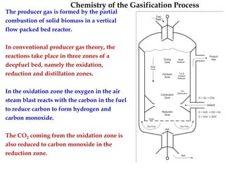
The producer gas is formed by the partial
combustion of solid biomass in a vertical
flow packed bed reactor.
In conventional producer gas theory, the
reactions take place in three zones of a
deepfuel bed, namely the oxidation,
reduction and distillation zones.
In the oxidation zone the oxygen in the air
steam blast reacts with the carbon in the fuel
to reduce carbon to form hydrogen and
carbon monoxide.
The CO2 coming from the oxidation zone is
also reduced to carbon monoxide in the
reduction zone.
Chemistry of the Gasification Process (Contd.,)
The final gas composition relies on the
water-gas shift reaction.
CO+H2O CO2 + H2
In the distillation zone the raw fuel is
preheated and carbonised giving of
condensable and non-condensable gases.
The process if called “gasification” as it
transfers the majority of the chemically
bound energy of the solid fuel in to the gas
phase.
As already stated, Pyrolysis ( destructive
distillation) converts organic wastes to char,
tar, oils and gas.
Chemistry of the Gasification Process (Contd.,)
Here gases produced are CO, Co2 and H2.
The organic plants which are used in
operation are called pyrolysis plants and
vessel in which this takes place is called
pyrolyzer.
Biomass Gasification (Contd.,)
Fixed bed gasifers
Updraft (or counter current) Gasifier:
In such a gasifier (where fuel and air move
in counter current manner) air enters below
the combustion zone and the ‘producer
gas’ leaves near the top of the gasifier.
The gas produced contains tar, water vapour
and the ash content is almost nil.
These gasifiers are suitable for stationary
engines (which use tar free fuels like
charcoal).
Biomass Gasification (Contd.,)
Down-draught (cocurrent) Gasifier:
In down draught gasifier air enters at the
combustion zone and the gas produced
leaves near the bottom of the gasifier.
Fuel (biomass) is loaded in the reactor from
the top.
As the fuel moves down it is subjected to
‘drying’ ( 120 ºC) and pyrolysis (200 – 600
ºC) where solid char, acetic acid, methanol
and water vapour are produced.
Descending volatiles and char reach the
oxidation zone (900 to 1200 ºC) where air is
injected to complete the combustion.
Down-draught Gasifier
Dr.N.Shankar Ganesh
( 120 ºC)
(200 – 600ºC
(900 to 1200 º
Biomass Gasification (Contd.,)
The products moving downwards, enter the
reduction zone (900 to 600 ºC) where
‘producer gas’ is formed by the action of
CO2 and water vapour on red hot charcoal.
The producer gas contains products like CO,
H2 and CH4; it is purified by passing
through coolers, tar is removed by
condensation, whereas soot and ash are
removed by centrifugal separation.
The downdraft gasifier is most commonly
used for engine applications because of its
ability to produce a relatively clean gas.
Fixed bed gasifiers can attain efficiency up
to 75% for conversion of solid biomass to
gaseous fuel.
Down-draught Gasifier
Cross Draft Gasifier
Crossdraft gas producers, although they
have certain advantages over updraft and
downdraft gasifiers, they are not of ideal
type.
The disadvantages such as high exit gas
temperature, poor CO 2 reduction and high
gas velocity are the consequence of the
design.
Unlike downdraft and updraft gasifiers, the
ash bin, fire and reduction zone in crossdraft
gasifiers are separated.
This design characteristics limit the type of
fuel for operation to low ash fuels such as
wood, charcoal and coke.
Cross-Draught Gasifier
Dr.N.Shankar Ganesh
Cross Draft Gasifier (Contd.,)
The load following ability of crossdraft
gasifier is quite good due to concentrated
partial zones which operates at temperatures
up to 2000 o c.
Start up time (5-10 minutes) is much faster
than that of downdraft and updraft units.
The relatively higher temperature in cross
draft gas producer has an obvious effect on
gas composition such as high carbon
monoxide, and low hydrogen and methane
content when dry fuel such as charcoal is
used.
Crossdraft gasifier operates well on dry air
blast and dry fuel.
Cross-Draught Gasifier
Fluidized Bed Gasifier
A fluidized bed gasifier is most versatile
and any biomass, including sewage sludge
pulping effluents etc., can be gasified by
using this type of gasifier.
It consists of a hot bed of inert solid
particles of sand or crushed refractory
supported on a fine mesh or grid.
An upward air current fluidizes the bed
material.
The pressurized air starts bubbling through
the bed and the particles attain a stage of
high turbulence, and the bed exhibits fluid
like properties.
Fluidized Bed Gasifier
Dr.N.Shankar Ganesh
Fluidized Bed Gasifier
Fluidized Bed Gasifier (Contd.,)
A uniform temperature within the range of
750 to 950 ºC is maintained so that the ash
zones do not get heated to its initial
deformation temperature and this prevents
clinkering or slagging.
In the fluidised bed, a large surface is
created and the constantly changing area per
unit volume provides a higher conversion
efficiency at low operating temperatures,
compared to fixed beds.
Low grade fuels of even non-uniform size
and high moisture content can be gasified
by the high heating capacity of sand and
uniform temperature of fluidized bed.
Fluidized Bed Gasifier
Fluidized Bed Gasifier (Contd.,)
To put the gasifier in use the bed material is
heated to ignition temperature of the fuel
and biomass is then injected causing rapid
oxidation and gasification.
The fuel gas thus obtained is conditioned
and cleaned for utilization as an engine fuel.
Advantages of fluidised bed gasifier:
1. High heat storage capacity
2. Simple operation
3. Compact size
4. Consistent combustion rate
5. High output rate
6. Quick startup
7. Fuel flexibility
8. High moisture content fuel can be used
Fluidized Bed Gasifier
Bio Gas Digester
• A biogas digester (also known as a biogas plant) is a large tank where inside
biogas is produced through the through a process called anaerobic digestion.
decomposition/breakdown of organic matter
• It is called a digester because organic material is eaten and digested by bacteria
to produce biogas.
• Biogas digester delivers methane as rich gas which contains methane (CH4),
carbon dioxide (CO2) and other impurities.
• The biogas plants have the rural applications for converting cow dung,
agricultural wastes etc. into biogas.
• Biogas plants are built in various sizes having the capacity of 0.5 m3/day to
650 m3/day. The most popular size in India is of 3 m3/day capacity.
Biogas Raw Materials
The following organic matter rich in feedstocks are suitable for biogas
production.
• 1. Animal wastes: Cattle dung, poultry droppings, fish wastes, leather and
hood wastes, elephant dung.
• 2. Human wastes: Faeces and urine
• 3. Agricultural wastes: Aquatic and terrestrial weeds crop residue, sugarcane
trash, bagasse, cotton and textile wastes and tea wastes.
• 4. Industrial wastes: Sugar factory, tannery, paper etc.
Average Composition of biogas
• Classification of Digestion Processes Biogas technology
is concerned to microorganisms. These are living
creatures which are microscopic in size and invisible to
unaided eyes. Different types of microorganisms are
bacteria, fungi, virus, etc. Again, these bacteria are
classified into two types. They are as follows:
• 1. Beneficial bacteria (biogas compost, vinegar) 2.
Harmful bacteria (cholera, typhoid, diphtheria). Based
on the oxygen requirements, the digestion processes
can be divided into two major groups. They are as
follows: 1. Aerobic (oxygen presence) 2. Anaerobic
(absence of oxygen).

More Related Content

What's hot

Solar Air Conditioner
Solar Air ConditionerSolar Air Conditioner
Solar Air Conditionernasa24
 
Automobile Engineering Lecture Notes
Automobile Engineering Lecture NotesAutomobile Engineering Lecture Notes
Automobile Engineering Lecture NotesFellowBuddy.com
 
Solar Water Heater System
Solar Water Heater	SystemSolar Water Heater	System
Solar Water Heater SystemOwais Ahmad
 
power plant engineering
power plant engineeringpower plant engineering
power plant engineeringGulfaraz alam
 
Wind energy renewable energy resources
Wind energy renewable energy resourcesWind energy renewable energy resources
Wind energy renewable energy resourcesDrBilalAhmadZafarAmi
 
3. solar water heater
3. solar water heater3. solar water heater
3. solar water heaterAshu0711
 
Solar energy by hadi @bau
Solar energy by hadi @bauSolar energy by hadi @bau
Solar energy by hadi @bauMd Abdul Hai
 
Solar flat plate collector
Solar flat plate collectorSolar flat plate collector
Solar flat plate collectorBipin Gupta
 
Future of wind energy in india
Future of wind energy in indiaFuture of wind energy in india
Future of wind energy in indiaManoj Bhambu
 
Windmill its parts and types
Windmill its parts and types Windmill its parts and types
Windmill its parts and types Umer Azeem
 

What's hot (20)

Solar Air Conditioner
Solar Air ConditionerSolar Air Conditioner
Solar Air Conditioner
 
Solar thermal power
Solar thermal powerSolar thermal power
Solar thermal power
 
PROJECT REPORT ON SOLAR DRYER
PROJECT REPORT ON SOLAR DRYERPROJECT REPORT ON SOLAR DRYER
PROJECT REPORT ON SOLAR DRYER
 
Solar water heating system
Solar water heating systemSolar water heating system
Solar water heating system
 
FINAL PROJECT VAWT
FINAL PROJECT VAWTFINAL PROJECT VAWT
FINAL PROJECT VAWT
 
Automobile Engineering Lecture Notes
Automobile Engineering Lecture NotesAutomobile Engineering Lecture Notes
Automobile Engineering Lecture Notes
 
Solar Energy Option
Solar Energy OptionSolar Energy Option
Solar Energy Option
 
Solar energy storage
Solar energy storageSolar energy storage
Solar energy storage
 
Solar Water Heater System
Solar Water Heater	SystemSolar Water Heater	System
Solar Water Heater System
 
power plant engineering
power plant engineeringpower plant engineering
power plant engineering
 
Demand Side Management
Demand Side ManagementDemand Side Management
Demand Side Management
 
Wind energy renewable energy resources
Wind energy renewable energy resourcesWind energy renewable energy resources
Wind energy renewable energy resources
 
solar thermal energy
solar thermal energysolar thermal energy
solar thermal energy
 
3. solar water heater
3. solar water heater3. solar water heater
3. solar water heater
 
Energy management system
Energy management systemEnergy management system
Energy management system
 
Solar energy by hadi @bau
Solar energy by hadi @bauSolar energy by hadi @bau
Solar energy by hadi @bau
 
Solar flat plate collector
Solar flat plate collectorSolar flat plate collector
Solar flat plate collector
 
Future of wind energy in india
Future of wind energy in indiaFuture of wind energy in india
Future of wind energy in india
 
What does peak shaving mean
What does peak shaving meanWhat does peak shaving mean
What does peak shaving mean
 
Windmill its parts and types
Windmill its parts and types Windmill its parts and types
Windmill its parts and types
 

Similar to UNIT IV WIND ENERGY.pptx

Similar to UNIT IV WIND ENERGY.pptx (20)

Wind Power and New Technology
Wind Power and New TechnologyWind Power and New Technology
Wind Power and New Technology
 
Wind energy system
Wind energy systemWind energy system
Wind energy system
 
Wind Energy
Wind EnergyWind Energy
Wind Energy
 
windenergy-210626034246.pdf
windenergy-210626034246.pdfwindenergy-210626034246.pdf
windenergy-210626034246.pdf
 
Wind energy
Wind energyWind energy
Wind energy
 
Inter wind 1(1)
Inter wind 1(1)Inter wind 1(1)
Inter wind 1(1)
 
physics.pptx
physics.pptxphysics.pptx
physics.pptx
 
wind turbine detailed presentation .ppt
wind turbine detailed presentation  .pptwind turbine detailed presentation  .ppt
wind turbine detailed presentation .ppt
 
INTRODUCTION wind energy and its type .pptx
INTRODUCTION wind energy and its type .pptxINTRODUCTION wind energy and its type .pptx
INTRODUCTION wind energy and its type .pptx
 
Windpower
WindpowerWindpower
Windpower
 
wttt.pdf
wttt.pdfwttt.pdf
wttt.pdf
 
Wind energy
Wind energyWind energy
Wind energy
 
wind Power
wind Power wind Power
wind Power
 
Power wind
Power windPower wind
Power wind
 
Windpower
WindpowerWindpower
Windpower
 
Wind power
Wind powerWind power
Wind power
 
Windpower
WindpowerWindpower
Windpower
 
wind turbines
wind turbineswind turbines
wind turbines
 
Wind turbines
Wind turbinesWind turbines
Wind turbines
 
Wind ppt
Wind pptWind ppt
Wind ppt
 

More from Manivannan727901

UNIT-III_Steam_Turbine (1).pdf
UNIT-III_Steam_Turbine (1).pdfUNIT-III_Steam_Turbine (1).pdf
UNIT-III_Steam_Turbine (1).pdfManivannan727901
 
heattreatments-130228110431-phpapp02.ppt
heattreatments-130228110431-phpapp02.pptheattreatments-130228110431-phpapp02.ppt
heattreatments-130228110431-phpapp02.pptManivannan727901
 
solar radiation measuring insturments.ppt
solar radiation measuring insturments.pptsolar radiation measuring insturments.ppt
solar radiation measuring insturments.pptManivannan727901
 
unit 2 Renewable energy sources
unit 2 Renewable energy sources unit 2 Renewable energy sources
unit 2 Renewable energy sources Manivannan727901
 
IC Engine Unit 4 ALTERNATE FUELS.ppt
IC Engine Unit 4 ALTERNATE FUELS.pptIC Engine Unit 4 ALTERNATE FUELS.ppt
IC Engine Unit 4 ALTERNATE FUELS.pptManivannan727901
 

More from Manivannan727901 (6)

UNIT-III_Steam_Turbine (1).pdf
UNIT-III_Steam_Turbine (1).pdfUNIT-III_Steam_Turbine (1).pdf
UNIT-III_Steam_Turbine (1).pdf
 
heattreatments-130228110431-phpapp02.ppt
heattreatments-130228110431-phpapp02.pptheattreatments-130228110431-phpapp02.ppt
heattreatments-130228110431-phpapp02.ppt
 
solar radiation measuring insturments.ppt
solar radiation measuring insturments.pptsolar radiation measuring insturments.ppt
solar radiation measuring insturments.ppt
 
unit 2 Renewable energy sources
unit 2 Renewable energy sources unit 2 Renewable energy sources
unit 2 Renewable energy sources
 
IC Engine Unit 4 ALTERNATE FUELS.ppt
IC Engine Unit 4 ALTERNATE FUELS.pptIC Engine Unit 4 ALTERNATE FUELS.ppt
IC Engine Unit 4 ALTERNATE FUELS.ppt
 
UNIT 5 HCCI.ppt
UNIT 5 HCCI.pptUNIT 5 HCCI.ppt
UNIT 5 HCCI.ppt
 

Recently uploaded

Introduction-To-Agricultural-Surveillance-Rover.pptx
Introduction-To-Agricultural-Surveillance-Rover.pptxIntroduction-To-Agricultural-Surveillance-Rover.pptx
Introduction-To-Agricultural-Surveillance-Rover.pptxk795866
 
Internship report on mechanical engineering
Internship report on mechanical engineeringInternship report on mechanical engineering
Internship report on mechanical engineeringmalavadedarshan25
 
Gfe Mayur Vihar Call Girls Service WhatsApp -> 9999965857 Available 24x7 ^ De...
Gfe Mayur Vihar Call Girls Service WhatsApp -> 9999965857 Available 24x7 ^ De...Gfe Mayur Vihar Call Girls Service WhatsApp -> 9999965857 Available 24x7 ^ De...
Gfe Mayur Vihar Call Girls Service WhatsApp -> 9999965857 Available 24x7 ^ De...srsj9000
 
Call Girls Narol 7397865700 Independent Call Girls
Call Girls Narol 7397865700 Independent Call GirlsCall Girls Narol 7397865700 Independent Call Girls
Call Girls Narol 7397865700 Independent Call Girlsssuser7cb4ff
 
main PPT.pptx of girls hostel security using rfid
main PPT.pptx of girls hostel security using rfidmain PPT.pptx of girls hostel security using rfid
main PPT.pptx of girls hostel security using rfidNikhilNagaraju
 
OSVC_Meta-Data based Simulation Automation to overcome Verification Challenge...
OSVC_Meta-Data based Simulation Automation to overcome Verification Challenge...OSVC_Meta-Data based Simulation Automation to overcome Verification Challenge...
OSVC_Meta-Data based Simulation Automation to overcome Verification Challenge...Soham Mondal
 
power system scada applications and uses
power system scada applications and usespower system scada applications and uses
power system scada applications and usesDevarapalliHaritha
 
Gurgaon ✡️9711147426✨Call In girls Gurgaon Sector 51 escort service
Gurgaon ✡️9711147426✨Call In girls Gurgaon Sector 51 escort serviceGurgaon ✡️9711147426✨Call In girls Gurgaon Sector 51 escort service
Gurgaon ✡️9711147426✨Call In girls Gurgaon Sector 51 escort servicejennyeacort
 
Study on Air-Water & Water-Water Heat Exchange in a Finned Tube Exchanger
Study on Air-Water & Water-Water Heat Exchange in a Finned Tube ExchangerStudy on Air-Water & Water-Water Heat Exchange in a Finned Tube Exchanger
Study on Air-Water & Water-Water Heat Exchange in a Finned Tube ExchangerAnamika Sarkar
 
VIP Call Girls Service Hitech City Hyderabad Call +91-8250192130
VIP Call Girls Service Hitech City Hyderabad Call +91-8250192130VIP Call Girls Service Hitech City Hyderabad Call +91-8250192130
VIP Call Girls Service Hitech City Hyderabad Call +91-8250192130Suhani Kapoor
 
SPICE PARK APR2024 ( 6,793 SPICE Models )
SPICE PARK APR2024 ( 6,793 SPICE Models )SPICE PARK APR2024 ( 6,793 SPICE Models )
SPICE PARK APR2024 ( 6,793 SPICE Models )Tsuyoshi Horigome
 
complete construction, environmental and economics information of biomass com...
complete construction, environmental and economics information of biomass com...complete construction, environmental and economics information of biomass com...
complete construction, environmental and economics information of biomass com...asadnawaz62
 
IVE Industry Focused Event - Defence Sector 2024
IVE Industry Focused Event - Defence Sector 2024IVE Industry Focused Event - Defence Sector 2024
IVE Industry Focused Event - Defence Sector 2024Mark Billinghurst
 
Biology for Computer Engineers Course Handout.pptx
Biology for Computer Engineers Course Handout.pptxBiology for Computer Engineers Course Handout.pptx
Biology for Computer Engineers Course Handout.pptxDeepakSakkari2
 
Churning of Butter, Factors affecting .
Churning of Butter, Factors affecting  .Churning of Butter, Factors affecting  .
Churning of Butter, Factors affecting .Satyam Kumar
 
Decoding Kotlin - Your guide to solving the mysterious in Kotlin.pptx
Decoding Kotlin - Your guide to solving the mysterious in Kotlin.pptxDecoding Kotlin - Your guide to solving the mysterious in Kotlin.pptx
Decoding Kotlin - Your guide to solving the mysterious in Kotlin.pptxJoão Esperancinha
 
HARMONY IN THE HUMAN BEING - Unit-II UHV-2
HARMONY IN THE HUMAN BEING - Unit-II UHV-2HARMONY IN THE HUMAN BEING - Unit-II UHV-2
HARMONY IN THE HUMAN BEING - Unit-II UHV-2RajaP95
 

Recently uploaded (20)

Introduction-To-Agricultural-Surveillance-Rover.pptx
Introduction-To-Agricultural-Surveillance-Rover.pptxIntroduction-To-Agricultural-Surveillance-Rover.pptx
Introduction-To-Agricultural-Surveillance-Rover.pptx
 
9953056974 Call Girls In South Ex, Escorts (Delhi) NCR.pdf
9953056974 Call Girls In South Ex, Escorts (Delhi) NCR.pdf9953056974 Call Girls In South Ex, Escorts (Delhi) NCR.pdf
9953056974 Call Girls In South Ex, Escorts (Delhi) NCR.pdf
 
Internship report on mechanical engineering
Internship report on mechanical engineeringInternship report on mechanical engineering
Internship report on mechanical engineering
 
Gfe Mayur Vihar Call Girls Service WhatsApp -> 9999965857 Available 24x7 ^ De...
Gfe Mayur Vihar Call Girls Service WhatsApp -> 9999965857 Available 24x7 ^ De...Gfe Mayur Vihar Call Girls Service WhatsApp -> 9999965857 Available 24x7 ^ De...
Gfe Mayur Vihar Call Girls Service WhatsApp -> 9999965857 Available 24x7 ^ De...
 
Call Girls Narol 7397865700 Independent Call Girls
Call Girls Narol 7397865700 Independent Call GirlsCall Girls Narol 7397865700 Independent Call Girls
Call Girls Narol 7397865700 Independent Call Girls
 
Call Us -/9953056974- Call Girls In Vikaspuri-/- Delhi NCR
Call Us -/9953056974- Call Girls In Vikaspuri-/- Delhi NCRCall Us -/9953056974- Call Girls In Vikaspuri-/- Delhi NCR
Call Us -/9953056974- Call Girls In Vikaspuri-/- Delhi NCR
 
main PPT.pptx of girls hostel security using rfid
main PPT.pptx of girls hostel security using rfidmain PPT.pptx of girls hostel security using rfid
main PPT.pptx of girls hostel security using rfid
 
OSVC_Meta-Data based Simulation Automation to overcome Verification Challenge...
OSVC_Meta-Data based Simulation Automation to overcome Verification Challenge...OSVC_Meta-Data based Simulation Automation to overcome Verification Challenge...
OSVC_Meta-Data based Simulation Automation to overcome Verification Challenge...
 
power system scada applications and uses
power system scada applications and usespower system scada applications and uses
power system scada applications and uses
 
Gurgaon ✡️9711147426✨Call In girls Gurgaon Sector 51 escort service
Gurgaon ✡️9711147426✨Call In girls Gurgaon Sector 51 escort serviceGurgaon ✡️9711147426✨Call In girls Gurgaon Sector 51 escort service
Gurgaon ✡️9711147426✨Call In girls Gurgaon Sector 51 escort service
 
Study on Air-Water & Water-Water Heat Exchange in a Finned Tube Exchanger
Study on Air-Water & Water-Water Heat Exchange in a Finned Tube ExchangerStudy on Air-Water & Water-Water Heat Exchange in a Finned Tube Exchanger
Study on Air-Water & Water-Water Heat Exchange in a Finned Tube Exchanger
 
🔝9953056974🔝!!-YOUNG call girls in Rajendra Nagar Escort rvice Shot 2000 nigh...
🔝9953056974🔝!!-YOUNG call girls in Rajendra Nagar Escort rvice Shot 2000 nigh...🔝9953056974🔝!!-YOUNG call girls in Rajendra Nagar Escort rvice Shot 2000 nigh...
🔝9953056974🔝!!-YOUNG call girls in Rajendra Nagar Escort rvice Shot 2000 nigh...
 
VIP Call Girls Service Hitech City Hyderabad Call +91-8250192130
VIP Call Girls Service Hitech City Hyderabad Call +91-8250192130VIP Call Girls Service Hitech City Hyderabad Call +91-8250192130
VIP Call Girls Service Hitech City Hyderabad Call +91-8250192130
 
SPICE PARK APR2024 ( 6,793 SPICE Models )
SPICE PARK APR2024 ( 6,793 SPICE Models )SPICE PARK APR2024 ( 6,793 SPICE Models )
SPICE PARK APR2024 ( 6,793 SPICE Models )
 
complete construction, environmental and economics information of biomass com...
complete construction, environmental and economics information of biomass com...complete construction, environmental and economics information of biomass com...
complete construction, environmental and economics information of biomass com...
 
IVE Industry Focused Event - Defence Sector 2024
IVE Industry Focused Event - Defence Sector 2024IVE Industry Focused Event - Defence Sector 2024
IVE Industry Focused Event - Defence Sector 2024
 
Biology for Computer Engineers Course Handout.pptx
Biology for Computer Engineers Course Handout.pptxBiology for Computer Engineers Course Handout.pptx
Biology for Computer Engineers Course Handout.pptx
 
Churning of Butter, Factors affecting .
Churning of Butter, Factors affecting  .Churning of Butter, Factors affecting  .
Churning of Butter, Factors affecting .
 
Decoding Kotlin - Your guide to solving the mysterious in Kotlin.pptx
Decoding Kotlin - Your guide to solving the mysterious in Kotlin.pptxDecoding Kotlin - Your guide to solving the mysterious in Kotlin.pptx
Decoding Kotlin - Your guide to solving the mysterious in Kotlin.pptx
 
HARMONY IN THE HUMAN BEING - Unit-II UHV-2
HARMONY IN THE HUMAN BEING - Unit-II UHV-2HARMONY IN THE HUMAN BEING - Unit-II UHV-2
HARMONY IN THE HUMAN BEING - Unit-II UHV-2
 

UNIT IV WIND ENERGY.pptx

  • 1. UNIT IV WIND ENERGY • Sources and potentials, horizontal and vertical axis windmills, performance characteristics, Betz criteria BIO-MASS: Principles of Bio-Conversion, Anaerobic/aerobic digestion, types of Bio-gas digesters, gas yield, combustion characteristics of bio- gas, utilization for cooking, I.C.Engine operation and economic aspects.
  • 2. INTRODUCTION TO WIND ENERGY • Wind energy is an indirect form of solar energy. • The uneven Earth's terrains get unequally heated by the sun rays. It makes some regions of the earth warmer than others. • The hot air in the warmer regions becomes less dense and light and thus it rises up. • This upward movement of hot air creates a vacuum which is immediately filled up by cold air from the adjacent cooler realms. • Wind power is the conversion of wind energy into a useful form of energy such as using Wind turbines to make electricity, windmills for mechanical power, wind pumps for water pumping or drainage or sails to propel ships.
  • 3. Source or Origin of Wind • Wind is produced by the uneven heating of the Earth's surface. • The poles of the Earth receive less energy from the Sun than the equator. Among these twos the dry land heats up (and cools down) more quickly than sea. • The Earth's surface is made of different types of land and water, it absorbs sun' radiant energy at different rates. • The non uniform thermal effects combine with the dynamic effects from the Earth's rotation that produce prevailing wind patterns. • There are also minor changes in the flow of the air as result of the differential heating of sea and land. • The nature of terrain ranging from mountain and valleys to more local obstacles such as buildings and trees also has an important effect of the origin of wind.
  • 4. Characteristics of Wind Energy • Wind-power systems do not pollute the atmosphere. • Fuel provision and transport are not required in wind- power systems. • Wind energy is a renewable source of energy. • competitive With conventional power generating system when produced on a large scale.
  • 5. Wind Speed • Power in the wind is proportional to the cube of the wind speed. • It is well known that the highest wind velocities are generally found on hill tops, exposed coasts and out at sea. • various parameters like the mean wind speed directional data and variations about the mean in the short-term (drafts), daily, seasonal and annual variations as well as variations with height. • These parameters are highly site specific and they can only be determined with sufficient accuracy by measurements at a particular site over a sufficiently long period. • General meteorological statistics may overestimate the wind speed at a specific site. • To calculate the amount of electricity that can be produced by wind turbines in a certain region.
  • 6. Wind Data • The wind is measured on the basis of many factors such as time availability, budget allocated for the measurement and accuracy needed for the estimation. • It is better to use metrological data/or civil aviation data. Basically, the measurements are wind speed and wind direction. • The standardized wind data should be used similar to a metrological department. • The metrological department collects data continuously about wind from many airports and data from anemometers located at 10 m height in order to follow the world standard. • But the height of the hub in a wind turbine is generally kept at more than 10 m. In that condition, the variations in speed of the wind with height are to be incorporated for predicting the energy available in the wind. • Sometimes, anemometers provide inaccurate data due to the friction in bearings rotating slowly.
  • 7. Beaufort scale • The Beaufort scale is a scale for measuring wind speeds. • It is based on observation rather than accurate measurement. • It is the most widely used system to measure wind speed today. • The scale was developed in 1805 by Francis Beaufort, an officer of the Royal Navy and first officially used by HMS Beagle.
  • 8.
  • 9.
  • 10. • A wind farm or wind park, also called a wind power station or wind power plant, is a group of wind turbines in the same location used to produce electricity
  • 11. WIND ENERGY POTENTIAL • The power available in the wind over the earth surface is estimated to be 1.6x10^7MW which is more than the present energy requirement of the world. • The installation cost of wind power is Rs. 4 crore / MW which is almost same of conventional thermal power plants. • Asia was the largest regional market for the ninth consecutive year, representing nearly 48% of added capacity (with a total exceeding 235 GW by the end of year 2017), 30 countries had more than 1 GW in operation. • There has been remarkable growth of wind power installation in the world. • China leads the world in terms of total installed wind capacity (188.4 GW) and followed by the US (89 GW), Germany (56.1 GW), India (32.8 GW), Spain (20 GW), the UK (18.9 GW) and France (13.8 GW) at the end of 2017.
  • 12. Wind energy potential in India • The development of wind power in India began in the 1986 with first wind farms being se up in coastal areas of Maharashtra (Ratnagiri), Gujarat (Okha) and Tamil Nadu (Tuticorin) with 55 kW Vestas wind turbines. • The capacity has significantly increased in the last few years. • A total capacity of 32.85 GW has been established upto December, 2017. • The wind power projects in India are mainly spread across south, west and north regions while east and north-east regions have no grid connected wind power plant. • Wind power generation in India is highly influenced by the monsoon in India.
  • 13. • The strong south-west monsoon, starts in May-June, when cool, humid air moves towards the land and the weaker north-east monsoon, starts in October, when cool dry air moves towards the ocean. • During the period of March to August, the winds are uniform and strong over the Whole Indian peninsula, except the eastern peninsular coast. • Wind speed during the period of November to March is relatively weak. • Most of the capacity (7.97 GW) is installed in the state of Tamil Nadu in India.
  • 14.
  • 15. BASICS OF WIND ENERGY ELECTRICITY GENERATION • Typical components of a wind turbine are gearbox, rotor shaft and brake assembly being lifted into position. • In a wind farm, individual turbines are interconnected with a medium voltage (usually 34.5 kV) power collection system and communication networks. • At a substation, this medium-voltage electrical current is increased in voltage with a transformer for the connection to high voltage electric power transmission system. • Wind turbine is a rotating machine which converts the kinetic energy of wind into mechanical energy. • If the mechanical energy is directly used by the machinery such as a pump or grinding stones, the machine is usually called a windmill. • If the mechanical energy is converted into electricity, the machine is called a wind generator, wind turbine, Wind Power Unit (WPU), Wind Energy Converter (WEC) or aero-generator.
  • 17. Penetration • Penetration Wind energy penetration is defined as the fraction of energy produced by wind from the total available generation capacity. • The penetration depends on the existing generating plants, pricing mechanisms, capacity for storage or demand management and other factors. Variability and Intermittency • Electricity generated from wind power is highly variable at different time scales: from hour to hour, daily and seasonally. • Wind power forecasting methods are used but the predictability of wind plant output is again less for short-term operation. • Intermittency and non-dispatchable nature of wind energy production increase the cost for regulation and incremental operating reserve. • The variation in load and allowance for failure of large generating units require at low level of wind penetration reserve capacity thereby regulating the variability of wind generation. • Hybrid wind power can be used during low wind period. Wind power can be replaced by other power stations during low wind period.
  • 18. ADVANTAGES OF WIND POWER 1. Wind power emits absolutely no greenhouse gases. Therefore, there is no pollution. 2. Wind is obtained at free of cost. 3. Wind power is helpful in supplying electricity to remote areas. 4. Wind energy itself is both renewable and sustainable. The wind will never run out. 5. The potential of wind power is enormous i.e. 20 times more than what the entire human population needs. 6. Wind power generation is cost effective and reliable. Wind power is an ideal choice for micro-generation. 7. Wind turbines are fairly low in maintenance. 8. As wind energy is free, running costs are often low
  • 19. DISADVANTAGES OF WIND POWER 1. Wind is a fluctuating (intermittent) source of energy and it is not suited to meet the base load energy demand. 2. Wind energy requires some form of energy storage e.g. batteries and pumped hydro. 3. The manufacturing and installation of wind turbines require heavy upfront investments. 4. Wind turbines can be a threat to wildlife (e.g. birds, bats). 5. Some wind turbines tend to generate a lot of noise which can be unpleasant. 6. Wind energy has low energy density but it is favourable in many geographical locations from cities and forests. 7. Wind power can even affect the national security because wind farms cause holes in RADAR coverage as the blades on turbines confuse the system.
  • 20. APPLICATIONS OF WIND ENERGY • Utility interconnected wind turbines generate power which is synchronous with the grid and are used to reduce utility bills by displacing the utility power used in the household and by selling the excess power back to the electric company. • Wind turbines for remote homes (off the grid) generate DC current for battery charging. • Wind turbines for remote water pumping generate 3 phase AC current suitable for driving an electrical submersible pump directly. • Wind turbines suitable for residential or village scale wind power range from 500 W to 50 kW.
  • 22.
  • 23. Overall conversion efficiency • Overall conversion efficiency can also be given in another tern called power coefficient (Cp). • It is defined as the ratio of the output power produced to the power available in the wind. • The power coefficient is a function of both tip speed ratio and blade pitch angle. • The overall conversion efficiency of the machine is a function of the following factors. • Wind velocity • Angular of velocity of rotor in the wind turbine • Pitch angle • Design of aerofoil section and • Number of blades.
  • 25. Derivation of Betz Criteria or Maximum Wind Power and Efficiency
  • 26. Betz criteria or Betz Emit • Betz criteria or Betz Emit is the theoretical limit assigned to efficiency of a wind turbine. • It states that no turbine can convert more than 59.3 % of wind kinetic energy into mechanical energy. • Thus, the value of power coefficient (CO is limited to Betz limit. • For a well-designed turbine, the efficiency lies in the range of 35-45 %.
  • 27. WIND ENERGY CONVERSION • The wind energy can be extracted from lift force alone or combination of lift and drag force. • Lift force acts perpendicular to air flow direction. • Drag force acts parallel to the wind direction. • The lift is produced by the change in velocity of air stream which speeds up the air flow thereby creating a pressure drop. • So, the pressure drop forces the lift surface from high pressure side to low pressure side of an aerofoil. • If the air pressure increases on the low pressure side, enormous turbulence is produced which reduces the lift force and it leads to increase the drag significantly called stalling.
  • 28.
  • 29. Aerodynamics of Wind Turbine • In wind turbines, aerodynamics deals with the relative motion between moving air and stationary aerofoil. • The aerofoil is the cross section of the blade of the wind turbine. • It is the shape designed to create maximum lift force when air flows over it. • In the wind turbine, linear kinetic energy associated with the wind is converted into the rotational motion that is required to turn the electrical generator for power generation. • This change is accomplished by a rotor that has one, two or three blades or aerofoils attached to the hub. • The wind flowing over the surfaces of these aerofoils generates the forces that cause the motor to run.
  • 30.
  • 31. • Wind passes more rapidly over the longer (upper) path of the aerofoil in comparison to the shorter (lower) path. • High and low pressure regions can be identified by using Bernoulli's equation. • Therefore, low pressure is created in the upper surface of the aerofoil and high pressure in its lower surface. • The pressure difference between top and bottom surfaces of the aerofoil results a force called aerodynamic lift as air moves from high-pressure region to low- pressure region. • The upward force due to aerodynamic lift pushes the blades to move up. • Hence, in aerodynamic analysis of wind turbines, both lift and drag forces are important for their optimisation in efficient design.
  • 32. Components of wind turbines
  • 33.
  • 34. Wind turbine or windmill • A system of blades fixed on a tower is rotated by the wind to either produce mechanical work or electrical energy. • The wind turbine may be located either upwind or downwind of the power. • In the upwind location, the wind encounters the turbine before reaching the tower. • Downwind machines have the rotor placed on the lee side of the tower. • They have the theoretical advantage that they may be built without a yaw mechanism
  • 35.
  • 36. Nacelle • It includes gearbox, low- and high-speed shafts, generator controller and brake. • It is placed at the top of the tower and it is connected to the rotor.
  • 37. Rotor • The hub and blades together compose the rotor. Most of the horizontal-axis wind turbines use two or three blades in an upwind design. • Blades are manufactured frog Fibreglass-Reinforced Polyester (FRP), wood laminates, steel or aluminium. • A FRP blade is comparatively lighter and it exerts less stress on bearing and rotor hubs. • Other manufacturers use steel blades because of the ease of fabrication, greater strength and lower cost. • Sometimes, wood laminates blades are also used due to their excellent fatigue resistance properties. • Vertical axis wind-turbine manufacturers often use extruded aluminium blades.
  • 38. Hub and shaft • Rotors of the wind turbine are attached with the shaft and hub assembly. • The hub is front portion of the shaft which faces the wind direction. • It is normally of conical shape. • The other end of the shaft is attached to the transmission system of the wind turbine.
  • 39. Anemometer • This device is used for the measurement of speed. • The wind speed is also fed to the controller as it is one of the variables for controlling pitch angle and yaw. • Wind turbines are available in various sizes according to the potential 'to generate electricity in ideal wind conditions. It is called "rated capacity.“ • Wind turbine capacity ratings range from 250 W to 1.65 MW. Electricity production and consumption are referred in kilowatt-hours (kWh).
  • 40. Robinson Cup Anemometer Proster Handheld Anemometer
  • 41. Transmission system • The transmission system contains a gearbox, clutch and braking system to stop the rotor in an emergency. • The purpose of the gearbox is to increase the speed of the rotor typically from 20 rpm to 50 rpm or from 1000 rpm to 1500 rpm which is required for driving the most types of electric generators. • The transmission system must be designed for high dynamic torque loads due to the fluctuating power output from the rotor
  • 42. Electric generator Major types of rotational electrical machines commonly used in a wind power generating systems: • The direct current ( DC ) machine, also known as a Dynamo • The alternating current ( AC ) synchronous machine, also known as an AC Generator • The alternating current ( AC ) induction machine, also known as an Alternator
  • 43. Yaw control system • It is used to continuously orient the rotor in the direction of the wind. • The horizontal-axis wind turbine has a yaw control system that turns the nacelle according to the actual wind direction using a rotary actuator attached to the gear ring at the top of the wind tower. • The wind direction must be perpendicular to the swept rotor area during normal operation of the wind turbine. • A slow closed-loop control system is used to control the yaw drives. • A wind vane mounted on the top of the nacelle senses the relative wind direction and the wind-turbine controller then operates the yaw drives.
  • 44.
  • 45. Storage • used to store energy when there is excess power developed and to discharge it when there is a lack in power. • The most common storage device is the lead-acid battery. • If the wind energy conversion system is to pump water and the pumped storage system of water is followed. • Usually, the electricity produced from wind energy is Direct Current (DC). • So, it should be converted into Alternating Current (AC) using an alternator before supplying it to the transmission grid for industrial and household appliances. Energy converters
  • 46. Towers • Mainly, wind turbines are kept on high towers due to light in weight. • In addition, wind turbines use light-weight towers than conventional mechanical wind mills. • Towers are basically made up of tubular steel or steel lattice. • There are two types of towers such as guyed (lattice or pole) towers and free-standing self-supporting towers. • If the location of wind mill has good topography, a guyed tower is used because of low cost. • The towers are designed to withstand wind loads and gravity loads. • The wind tower has to be mounted to a strong foundation in the ground. It is designed so that either its resonant
  • 47. Wind mill tower types Usually, the range of tower is from 12 m to 37 m for small wind applications and it is from 30 m to 75 m or higher for moderate wind turbines.
  • 48. TYPES OF WIND MILLS • Based on the axis of rotation of the rotor, wind turbines are further classified as follows: • Horizontal-axis wind machines • Vertical-axis wind machines.
  • 49.
  • 50. Horizontal-axis wind machines • In horizontal axis wind mills or turbines, the axis of rotation is horizontal with respect to the ground. • In this case, the rotating shaft is parallel to the ground and the blades are perpendicular to the ground. • Horizontal-axis or propeller-type turbines are more common and highly developed than vertical-axis turbines.
  • 51. • We call the wind turbines that have horizontal shaft as horizontal axis wind turbines or in short HAWT. • In HAWT the turbine rotor couples the electrical generator and this turbine generator set is placed on the top of the turbine tower. • A wind sensor with servomotor keeps the axis of the turbine along the path of the wind. • Although in small turbine a wind vane does the purpose. • The turbines commonly have a gearbox in between the turbine shaft and the generator shaft. • The functions of this gearbox are to provide mechanical coupling between these two shafts and to step up the slow rotating speed of the turbine blades to a high rotating speed of the generator.
  • 52.
  • 53. • A wind electric power generating station uses three blades horizontal axis wind turbines (HAWT). • Three blades design is more mechanically stable and can have less torque ripple. • The blade-length may be from 20 m to 80 m and usually of bright white colored so that any aircraft can view comfortably. • A turbine with the blade length of 80 m may have rating up to 8 MW. • The height of the large commercial turbine may be up to 70 m to 120 m and may be up to 160 meters in the extreme. • The modern wind turbine systems use steel tubular supporting poles. The RPM of a large wind turbine may be from 10 to 22.
  • 54. • Although, there are some designs in which the turbine rotor shaft directly couples the generator. • No one can control the wind pressure on the blades by any means it entirely depends on nature. • The designers provide a protective system to all large wind turbine which aligns the blade-edge faces depending on the speed of the wind so that we can avoid breakage of the blades during high wind pressure. We call this technique the feathering.
  • 55. Advantages • Variable blade pitch which give the turbine blades the optimum angle of attack. • The tall tower base allows an access to stronger wind in sites with wind shear. • Efficiency is high in receiving power through the whole rotation since the blades always move perpendicularly to the wind. • The face of a horizontal axis blade is struck by the wind at a consistent angle regardless of the position in its rotation.
  • 56. Disadvantages • HAWTs have difficulty operating in near ground and turbulent winds. Therefore, tall towers are required. • The tall towers and blades up to 90 m long are difficult to transport. • Tall HAWTs are difficult to install and they need very tall and expensive cranes and skilled operators. • Massive tower construction is required to support heavy blades, gearbox and generator. • Reflections on tall HAWTs may affect side lobes of radar installations creating signal clutter although filtering can suppress it. • Downwind variants suffer from fatigue and structural failure caused by turbulence when a blade passes through the tower's wind shadow. • HAWTs require an additional yaw control mechanism to turn the blades towards wind.
  • 57. Vertical-Axis Wind Turbines • In Vertical-Axis Wind Turbines (or VAWTs), the main rotor shaft arranged vertically and the axis of rotation is vertical with respect to the ground. • The key advantage of this arrangement is that the turbine does not need to be pointed into the wind streams to be effective because their operation is independent of wind direction and these vertical axis machines are called panemones. • It is an advantage on sites where the wind direction is highly variable. • • With a vertical axis turbine, the generator and gearbox can be placed near the ground so the tower does not need to support it and it is more accessible for maintenance. • Drawbacks are that some designs produce pulsating torque.
  • 58.
  • 59.
  • 60. • It is difficult to mount vertical-axis turbines on towers because they are often installed nor the base on which they rest such as the ground or a building rooftop. • The wind speed is slow at a lower altitude. So, less wind energy is available for a given size of turbine. • Air flow near the ground and other objects can create turbulent flow which can introduce issues of vibration including noise and bearing wear which may increase the maintenance or shorten the service life. • However, when a turbine is mounted on a rooftop, the building generally redirects wind over the roof and it can double the wind speed at the turbine. • • If the height of the rooftop mounted turbine tower is approximately 50% of the building height, it is near the optimum point for maximum wind energy and minimum wind turbulence.
  • 61. Types of vertical-axis wind turbines • 1. Darrieus rotor • 2. Savonius rotor (turbo machine) • 3. Multiple blade rotor • 4. Musgrove rotor • 5. Evans rotor.
  • 63. Darrieus rotor • This rotator is shaped such as an egg beater and it consists of two or three curved blades shaped such as aero foils. • The driving forces are lifting forces. This wind mill needs much less surface area. • The maximum torque occurs when a blade is moving across the wind of a speed much high than wind speed. • Initial movement may be initiated with the electrical generator used as a motor.
  • 64. Savonius rotor (turbo machine) Helical Savonius
  • 65. Savonius rotor (turbo machine) • This type of windmill has hollow circular cylinder sliced in half and the halves are mounted on a vertical shaft with a gap in between them. • There is a complicated motion of wind through and around the two curved sheet aerofoils rotates by drag force. • Torque is produced by the pressure difference between two sides of the half facing the wind. • It is quite efficient but it needs a large surface area. • It is simple in construction and it is inexpensive.
  • 66. Multiple blade rotor • It is the most widely used type of wind mill. • It has 15 to 20 blades made from metal sheets. • The sail type has three blades made by stitching out triangular pieces of canvas cloth. • these types run at low speed of 60 rpm to 80 rpm.
  • 67. Musgrove rotor In this rotor, the blades are vertical for normal power generation. This rotor has an advantage of fail-safe shut down in strong winds.
  • 68. Evans rotor • Vertical blades twist about a vertical axis speed for control and a fail-safe shut down. • Other types of wind mills available for the power generation are: Four-blade Dutch wind !Dill and propeller type. • For water pumping and small-battery operation, it is desirable to allow the rotor speed to vary.
  • 69.
  • 70.
  • 71. Advantages • A massive tower structure is less frequently used as VAWTs are more frequently mounted with lower bearing mounted near the ground. • Designs without yaw mechanisms are possible with fixed pitch rotor designs. • The generator of a VAWT can be located near the ground making it easy to maintain moving parts. • VAWTs have lower wind startup speeds than HAWTs. Typically, they start to generate electricity at 6 mph (10 km/h). • VAWTs may be built at locations where tall structures are prohibited. • VAWTs situated close to the ground can take the advantage of locations where I - mesas, hilltops and ridgelines. They pass funnel the wind and increase the wind velocity. • VAWTs may have a lower noise signature.
  • 72. Disadvantages • A VAWT which uses guy-wires to hold it in place puts stress at the bottom bearing as the whole weight of the rotor is on the bearing. • The stress in each blade due to wind loading changes its sign twice during each revolution as the apparent wind direction moves through 360°. This reversal of the stress increases the chance of failure by fatigue. • While VAWTs' parts are located on the ground, they are also located under the weight of the structure above it which can make changing of parts nearly impossible without dismantling the structure if it is not designed properly. • Having rotors located close to the ground where wind speed is low due to the ground's surface drag, VAWTs may not produce as much energy at a given site as a HAWT with the same footprint or height.
  • 73. PERFORMANCE CHARACTERISTICS OF WIND TURBINE ROTORS • Solidity • Tip-speed ratio • Performance coefficient • Torque • Rotor Power control
  • 74. • Solidity - Solidity is defined as the percentage of circumference of the rotor which contains the material instead of air. Solidity is calculated by Percentage of solidity = 31.8 x Number of blades x Blade width x Rotor diameter • Tip-speed ratio - It is defined as the ratio of speed of the blade tip of a windmill rotor to the speed of free wind. Tip-speed ratio = 0.052 x Rotor diameter x Rotation speed x Wind Speed • Performance coefficient -
  • 75. • Torque - It is the turning moment produced by the rotor. 1. It does mainly depend on solidity and tip speed ratio of the rotor. 2. Usually, the rotors with high solidity and low tip-speed ratio produce more torque than rotors with low solidity and high tip-speed ratio. 3. At the same time, high speed machines produce maximum performance coefficient but they have low starting torque. •Rotor prime control •There are two options for constant speed machines. (i) Stall-regulated wind turbines: The pitch angle distribution along the blades is constant for all wind speeds. At high wind speed STALL occurs. (i) Pitch-regulated wind turbines: The blades can be rotated about their radial axis during operation as the wind speed changes. It is therefore possible to have an optimum pitch angle at all wind speed and a relatively low cut-in wind velocity.
  • 76.
  • 77.
  • 78. PERFORMANCE CHARACTERISTICS OF WINDMILL The following are the four important characteristics of the wind speeds. 1. Cut-in wind speed 2. Design wind speed 3. Rated wind speed 4. Cut-out wind speed
  • 79. (a) Cut-in wind speed: It is the wind speed when the machine begins to produce power. It is typically between 3 m/s and 4 nt/s (10 km/hr and 14 km/hr, 7 mph and 9 mph). (b) Design wind speed: It is the wind speed when the windmill reaches its maximum efficiency. (c) Rated wind speed: It is also called nameplate capacity. It is the wind speed when the machine reaches its maximum output power. The rated wind speed is typically about 15 m/s (54 km/hr, 34 mph) which is about double the expected average speed of the wind. (d) cut-out wind speed: It is the maximum safe working wind speed and the speed at which the wind turbine is designed to be shut down by applying brakes to prevent damage to the system. • In addition to electrical or mechanical brakes, the turbine may be slowed down by stalling or furling.
  • 80. (i) Stalling: It is a self-correcting or passive strategy which can be used with fixed speed wind turbines. As the wind speed increases, the wind angle of attack is increased until it reaches its stalling angle at which point the "lift" force turning the blade is destroyed. (ii) Furling or feathering: It is a technique derived from sailing in which the pitch control of the blades is used to decrease the angle of attack which in turn reduces the "lift" on blades as well as the effective cross section of the aerofoil facing into the wind. • Survival wind speed: This is the maximum wind speed that a given wind turbine is designed to withstand above which it cannot survive. The survival speed of commercial wind turbines is in the range of 50 m/s (180 km/hr, 112 mph) to 72 m/s (259 km/hr, 161 mph). The most common survival speed is 60 m/s (216 km/hr, 134 mph).
  • 81. TYPES OF WIND POWER PLANTS • Remote or Off-grid wind power plants • Small scale or Stand-alone wind turbines plants • Medium scale wind turbine plants: 1. Single mode distribution 2. Multiple mode distribution • Hybrid wind power plants • Grid connected wind power plants • Wind forms
  • 82. SITE SELECTION FOR WIND ENERGY SYSTEMS (i) Plane site (ii) Hill top site (iii) Sea-shore site (iv) Off-shore shallow water site. Apart from the location selection, some other factors need to be considered such as technical, environmental, social, economic and other factors.
  • 83. The main considerations for selecting a site for wind turbine installation are as follows: 1. Wind farms are located away from main cities to avoid resistance to the air movement created by buildings. So, the flat area is advisable to locate wind mill. 2. The basic requirement for a successful use of a windmill is an adequate supply of wind speed. 3. The selected site should provide good average of wind velocity throughout the year for continuous generation of energy. 4. The proposed site should be checked for high altitude due to strong winds which will increase the electric power output of wind energy conversion system. 5. A stable ground is selected.
  • 84. 6. Small trees and grass are avoided under wind mill in order to minimise the installation cost because the height of tower needs to be increased in such case. 7. The selected site should be easily accessible to provide a transport facility for the erection of equipment and structures as well as for maintenance. 8. The site should be near the consumer for reducing the cost and transmission losses of the generated power. 9. The land cost should be favourable so that the total project cost is minimal. 10. Wind direction is also considered for the site selection. 11. Topography such as mountain gap helps to channelise and speed up winds. 12. The selection of coastal area or lake area for wind mill installation is favourable because differential heating of water and land generates wind of sufficient speed. The wind blow from the land to the sea during day time and it is reversed during night time.
  • 85. Bio mass • Biomass is organic matter produced by plants, both terrestrial (those grown on land) and aquatic (those grown in water) and their derivatives. • It includes forest crops and residues, crops grown especially for their energy content on “energy farms” and animal manure. • Biomass can be considered a renewable energy source because plants life renews and adds to itself every year. • It can also be considered a form of solar energy as the latter is used indirectly to grow these plants by photosynthesis.
  • 86. Bio mass resource • The resources of biomass falls in to three categories. (i) Biomass in its traditional solid mass (wood and agriculture residue) (ii) Biomass in non-traditional solid form (converted into liquid fuels) • The first category is to burn the biomass directly and get the energy. • In the second category, the biomass is converted into ethanol (ethyl alcohol) and methanol (methyl-alcohol) to be used as liquid fuels in engines. Dr.N.Shankar Ganesh •The third category is to ferment the biomass anaerobically to obtain a gaseous fuel called bio- gas.
  • 87. Biomass includes wood waste and bagasse (சர்க்கரை உற்பத்தியில் உண்டாகும் கழிவு பபாருள்), which have potential of generating substantial electric power. All these biomass are highly dispersed and bulky and contain large amounts of water (50 to 90 per cent). Thus it is not economical to transport them over long distances. However, biomass can be converted to liquid or gaseous fuels, thereby increasing its energy density and making feasible transportation over long distances. Bio mass resource (contd.,) Bagasse
  • 88. Terrestrial crops include i. Sugar crops such as sugarcane and sweet sorghum ii. Herbaceous crops which are non- woody plants that are easily converted into liquid or gaseous fuels. iii. Silviculture (forestry) plants such as cultured hybrid poplar, sycamore, sweet gum, alder, eucalyptus, and other hard woods. Bio mass resource (contd.,) Animal and human waste are indirect crops from which the methane for combustion and ethylene can be produced while retaining the fertilizer value of the manure. Aquatic crops are grown in fresh sea and brakish waters. Terrestrial crops Herbaceous crops
  • 89. Bio - fuels The energy stored in dry biomass like wood and straw is most easily released by direct combustion – although dry materials can also be converted into liquid and gaseous fuels (for later combustion) by a variety of techniques. Biomass that is wet or has a moisture content like sewage sludge and vegetable matter can be dried and burnt. However, it requires considerable energy to drive off the water, and this diminishes the value of the biomass as fuel. Sewage sludge
  • 90. Various Bio – fuels: Solids – wood straw Municipal refuse Liquids – Methanol and Ethanol Alcohols Vegetable oils Gases - biogas methane fuel gas
  • 91. BIOMASS ENERGY • The energy obtained from organic matter derived from biological organisms (plants and animals) is known as biomass energy or simply, bioenergy. • Biomass resources are mainly classified into two categories. They are as follows: 1. Biomass from cultivated fields, crops and forests. 2. Biomass from municipal waste, animal dung, forest waste, agricultural waste, bioprocess waste and fishery waste. • energy may be transformed either by chemical or biological. • Biomass cycle maintains the environmental balance of oxygen, CO2, rain etc. • Biomass is used for producing the process heat and electricity, gaseous and solid fuels, liquid and chemicals.
  • 92. Biomass Resources • Forests - wood, charcoal, eucalyptus, pine • Agricultural residues - straw, rice husk, coconut shell, groundnut shell, sugarcane baggage • Energy crops - cultivated plants produce raw material for bio-fuels. Eg: sugarcane, oil plants • Aquatic plants - plants grow very fast, seaweed and algae • Urban waste: Urban waste is of two types. They are given below. (a) Municipal solid waste (MSW) (b) Sewage (liquid waste).
  • 93.
  • 94. Advantages of bio energy • It is a renewable source. • The pollutant emissions from combustion of biomass are usually lesser than fossil fuels. • Commercial use of biomass may avoid or reduce the problems of waste disposal in other industries. • Use of biogas plants apart from supplying clean gas also leads to improved and stabilized sanitation. • The forestry and agricultural industries which supply feed stocks also provide substantial economic development opportunities in rural areas. • The energy storage is an in-built feature of it.
  • 95. Disadvantages of bio energy • It is dispersed and land intensive source. • It is often of low energy density. • It is also labour intensive and the cost of collecting large quantities of biomass for commercial application is significant. • More space area. • Source not available continuously
  • 96. Applications of Bio Energy • Biomass is an important source of energy and the most important fuel worldwide after coal, oil and natural gas. • Bio-energy in the form of biogas which is derived from biomass. • Biomass offers higher energy efficiency through form of biogas than by direct burning. • Some of the potential applications of bio energy are: cooking, mechanical applications, pumping and power generation. • Biomass gasifiers convert the solid biomass (basically wood waste, agricultural residues etc.) into a combustible gas mixture normally called producer gas.
  • 97. Applications of Bio Energy • Water pumping and electricity generation. - to operate a diesel engine • Heat generation. - for drying tea, flower, spices, kilns for baking tiles or potteries, furnaces for melting non-ferrous metals, boilers for process steam, etc • High efficiency wood burning stoves. • Bio fuels - Biodiesel can also be made by combining alcohol with vegetable oil or recycled cooking greases.
  • 98. BIOMASS FUELS • Biomass is an organic carbon based material that reacts with oxygen in combustion and natural metabolic process to release heat. • Some of its forms available to users are given below. 1. Fuel wood 2. Charcoal 3. Fuel pellets 4. Bio-ethanol 5. Bio gas 6. Producer gas 7. Vegetable oils (bio-diesel).
  • 99. • (i) Fuel wood: oldest source, combustion efficiency 16-20 MJ/kg. more useful forms such as charcoal or producer gas. • (ii) Charcoal: Charcoal is a clean, dry, solid fuel of black colour. It has 75-80% carbon content and has 1 energy density of about 30 MJ/kg. It is obtained by carbonization process of woody biomass, to achieve higher energy density per unit mass. It is also used for making high quality steel. • (iii) Fuel pellets: Crop residues such as straw, rice husk, cow dung-etc., are pressed to form lumps known 1 as fuel pellets and used as solid fuel. • (iv) Bio-ethanol: Ethanol (C21-150H) is a colourless liquid biofuel. Itsboiling point is 78°C and energy density is 26.9 MJ/kg. It can be derived from wet biomass containing sugar starches or cellulose. Commercial ethanol is used in specially designed ICengines.
  • 100. • (v) Biogas: Organic wastes from plants, animals and humans contain enough energy to contribute significantly to energy supply in many areas. Biogas is produced in a biogas fermenter. It is used for cooking, lighting, heating and operating small IC engines, etc. • (vi) Producer gas: Woody matter such as crop residue, wood chips, bagasse, rice husk, coconut shell etc., can be transformed to producer gas (wood gas, water gas or blue gas) by a method known as gasification of solid fuel. • (vii) Vegetable oils (bio-diesel): It can be used as such or blended with diesel as a diesel engine fuel.
  • 101. PRINCIPLES OF BIO-CONVERSION • Bioconversion, also known as biotransformation, is defined as the process of conversion of organic materials such as plant or animal waste into usable products or energy sources by biological processes or agents such as certain microorganisms. • Photosynthesis Definition: In simpler terms, the process of photosynthesis is used by plants and other organisms to convert the radiant energy/light energy into chemical energy, that can be used to perform daily tasks.
  • 102. Photosynthesis Process • Biomass energy is obtained by photosynthesis process. It means the synthesis process with light. • Photosynthesis converts solar energy into biomass energy. It consists in building up of simple carbohydrates such as sugar in the green leaf in the presence of sunlight. • Solar radiation incident on green plants and other photosynthesis organisms perform two basic functions. 1. Temperature control for chemical reactions to proceed and 2. Photosynthesis process. • It is the process of combining CO2, water and light energy to produce oxygen and carbohydrates (sugar, starches, celluloses and hemicelluloses).
  • 104. Necessary conditions for photosynthesis process 1. Light: It is one of the important input for biomass production. 2. CO2 concentration: It is the primary raw material for photosynthesis. 3. Temperature: Photosynthesis is restricted to the temperature range 0°C to 60°C.
  • 105. BIOMASS CONVERSION PROCESSES Broadly divided into four categories. 1. Physical process 2. Agrochemical process 3. Thermochemical processes a) Direct combustion b) Carbonisation c) Pyrolysis d) Gasification e) Liquefication 4. Biochemical process a) Anaerobic digestion b) b) Ethanol fermentation.
  • 106. Physical Conversion of Biomass • The simplest method of physical conversion of biomass is through the compression of combustible material. • It is densified by compression through the processes called briquetting and pelletisation. • Briquetting is brought about by compression baling. Densification is carried out by compression under a die. Briquettes (66 mm diameter and 96 mm thick) made from paddy husk or sawdust is a cheap and effective fuel for the tobacco-curing industry. • Pelletisation is a process in which wood is compressed and extracted in the form of rods (5-12 mm diameter and 12 mm long). • It has applications in steam power plants and gasification systems. • The purpose of pelletisation is to reduce the moisture contents and increase the energy density of wood for longer transportation haulage.
  • 107.
  • 108. Agrochemical Conversion of Biomass • production of fuels from plants. • Generally, liquid or solid fuels may be obtained directly from living or freshly cut plants. • The materials are called exudates. obtained by cutting into stems and trunks of the living plant or by crushing freshly harvested material. • The oil of the plant itself can directly be used as an energy source. • Categories of suitable materials are as follows: (i) Seeds (sunflower with 50% oil) (ii) Nuts (oil palm; coconut copra to 50% by mass of oil) (iii) Fruits (olive) (iv) Leaves (eucalyptus with 25% oil) (v) Tapped exudates (rubber latex) (vi) Harvested plants
  • 109. Thermochemical Process (1) Direct Combustion • oldest form of combustion. • It is burnt to provide heat for cooking, comfort heat (space heat), crop drying, factory processes and forming steam for electricity production and transport. (2) Carbonization • Carbonization is a process in which a fuel is heated without air to leave solid porous carbon. • Carbonization is the term which means destructive distillation of coal which is done in the absence air in order to obtain coke and other fractions having greater percentage of carbon than the original material • Done by four stages by increasing their temperature to remove volatile substance.
  • 111. STAGES OF CARBONIZATION 1.At 20 to 110°C The wood absorbs heat as it is dried giving off the moisture as water vapour. 2.At 110 to 270°C The final traces of the water are given off and the wood starts to decompose by giving off carbon monoxide, carbon dioxide, acetic acid, methanol etc. 3. At 270 to 290°C This is the point at which the exothermic decomposition takes place. 4.At 290 to 400°C As the breakdown of the wood continues the vapours given off consists of the combustible gases like carbon monoxide,hydrogen,methane along with carbon dioxide.. 5.At 400 t0 500°C The transformation of the wood to charcoal is completed.
  • 113. Dry Process Pyrolysis The biomass can be converted into more valuable and convenient fuels by the use of the thermochemical process called pyrolysis. The Pyrolysis process is carried out by heating the biomass in absence of air (or oxygen) or by partial combustion of some portion of the biomass in restricted presence of air (or oxygen). If pyrolysis is carried out at higher temperature (above 1000 ºC), maximum amount of gaseous product is formed. This high temperature pyrolysis is called gasification. Biomass conversion technologies (Contd.,)
  • 114. Biomass is heated in absence of oxygen, or partially combusted in a limited oxygen supply, to produce a hydrocarbon, rich in gas mixture (H2,CO2, CO, CH4 and lower hydrocarbons), an oil like liquid and a carbon rich solid residue (charcoal). The pyrolitic or ‘bio-oil’ produced can easily be transported and refined into a series of products similar to refining crude oil. There is no waste product, the conversion efficiency is high (82%) depending upon the feedstock used, the process temperature in reactor and the fuel/air ratio during combustion. Biomass conversion technologies (Contd.,)
  • 115. Gasification Gasification is conversion of a solid biomass, at a high temperature with controlled air, into a gaseous fuel. The output gas is known as producer gas, a mixture of H2 (15-20%), CO (10-25%), CH4(1-5%), CO2(9-12%) and N2(45-55%). The gas is more versatile than the solid biomass, it can be burnt to produce process heat and steam, or used in internal combustion engines or gas turbines to generate electricity. The gasification process renders the use of biomass which is relatively clean and acceptable in environmental terms. Biomass conversion technologies (Contd.,)
  • 116. Liquefaction Liquefaction of biomass can be processed through ‘fast’ or ‘flash’ pyrolysis , called ‘pyrolytic oil’ which is dark brown liquid of low viscosity and a mixture of hydrocarbons. Pyrolysis liquid is a good substitute for heating oil. Another liquefaction method is through methanol synthesis. Gasification of biomass produces synthetic gas containing a mixture of H2 and CO. Biomass conversion technologies (Contd.,)
  • 117. Liquefaction (Contd.,) The gas is purified by adjusting the hydrogen and carbon monoxide composition. Finally, the purified gas is subjected to liquefaction process, converted to methanol over a zinc chromium catalyst. Methanol can be used as liquid fuel. Biomass conversion technologies (Contd.,)
  • 118. • Thermal decomposition of organic components in biomass starts at 350 °C– 550 °C and goes up to 700 °C–800 °C in the absence of air/oxygen. • The long chains of carbon, hydrogen and oxygen compounds in biomass break down into smaller molecules in the form of gases, condensable vapours (tars and oils) and solid charcoal under pyrolysis conditions. • The products of biomass pyrolysis include biochar, bio-oil and gases including methane, hydrogen, carbon monoxide, and carbon dioxide.
  • 119.
  • 120. Biochemical conversion takes two forms. Anaerobic digestion and Fermentation. Anaerobic digestion involves the microbial digestion of biomass. An anaerobe is a micro – organism that can live and grow without air or oxygen, it gets its oxygen by the decomposition of matter containing it. Biomass chemical conversion technologies
  • 121. It had already been used on animal manure but is also possible with other biomass. The process takes place at low temperature upto 65 ºC, and requires a moisture content of atleast 80%. The Biological Process The digestion process begins with bacterial hydrolysis of the input materials in order to break down insoluble organic polymers such as carbohydrates and make them available for other bacteria. Acidogenic bacteria then convert the sugars and amino acids into carbon dioxide, hydrogen, ammonia, and organic acids. Biomass conversion technologies (Contd.,) Acetogenic bacteria then convert these resulting organic acids into acetic acid, along with additional ammonia, hydrogen, and carbon dioxide. Finally, methanogens convert these products to methane and carbon dioxide.
  • 122. It generates a gas consisting of mostly of CO2 and methane CH4 with minimum impurities such as hydrogen sulfide. The gas can be burned directly or upgraded to synthetic natural gas by removing the CO2 and impurities. The residue may consist of protein- rich sludge that can be used as animal feed and liquid effluents that are biologically treated by standard techniques and returned to the soil. Biomass conversion technologies (Contd.,)
  • 123. Wet processes: Anaerobic Digestion. Biogas is produced by the bacterial decomposition of wet sewage, animal dung or green plants in the absence of oxygen. The natural decay process, ‘anaerobic decomposition’ can be speeded up by using a thermally insulated air tight tank with a stirrer unit and heating system. The gas collects in the digester tank above the slurry and can be piped off continuously. At optimum temperature 35 ºC complete decomposition of animal or human faces takes around 10 days. Biomass conversion technologies (Contd.,)
  • 124. Anaerobic Digestion (contd.,) This process does not use air and hence produces the fuel gas methane. Here, the land-filled solids are sealed against contact with the atmospheric oxygen. The leachate (is any liquid that in passing through matter, extracts solutes, suspended solids or any other component of the material through which it has passed) is collected and pumped back into the landfill as in aerobic digestion. Additional liquid may be added to the laechate to help biodegradation of the waste. In the absence of oxygen, the waste is broken down into the methane, carbon-dioxide and digestate (sold residue). Biomass conversion technologies (Contd.,)
  • 125.
  • 126. Fermentation: It is the breakdown of complex molecules in organic compound under the influence of a ferment such as yeast, bacteria, enzymes etc. It is a well established and widely used technology for the conversion of grains and sugar crops into ethanol. Ethanol can be produced by decomposition of biomass containing sugar like sugarcane, cassava sweet sorghum, beet, potato, corn, grape etc into sugar molecules such as glucose (C6H12O6) and sucrose (C12H22O11). Biomass conversion technologies (Contd.,)
  • 127. Ethanol fermentation involves biological conversion of sugar into ethanol and CO2. C12H22O11 + H2O 2C6H12O6 C6H12O6 2C2H5OH + 2CO2 Ethanol has emerged as the major alcohol fuel and is blended with petrol. Biomass conversion technologies (Contd.,) fermentation
  • 128. Biomass Gasification Gasification Implies converting a solid or liquid into a gaseous fuel without leaving any solid carbonaceous residue. This process is carried out in a gasifier. Gasifiers It is an equipment which can gasify a variety of biomass such as wood waste, agricultural waste like stalks, and roots of various crops, maize cobs etc. In a gasifier, the biomass get dried, heated, pyrolysed, partially oxidised and reduced.
  • 129. Biomass Gasification (Contd.,) Advantages: Very easy operation Reliable operation Easy maintenance Sturdy construction Classification of Gasifiers A. According to the type of bed 1. Fixed bed gasifiers i) Updraft ii) Downdraft, and iii) Crossdraft B. According to the output power i) Small size gasifiers – up to 10 kW ii) Medium size gasifiers – 10 – 50 kW iii) Large size gasifiers – 50 – 300 kW iv) Very large gasifiers – 300 kW and above
  • 131. Chemistry of the Gasification Process The four basic processes of gasification are: 1. Drying of the fuel 2. Pyrolysis 3. Oxidation (combustion) 4. Reduction Drying of the fuel The fuel wood pellets are heated and dried at the top of the gasifier unit. Moisture contained in the wood pellets is removed in this region to a level below 20%. Pyrolysis The dried wood pellets enter the second zone called the Pyrolysis zone. The gaseous products from devolatilization are partially burnt with the existing air. This process is termed “Pyrolysis”.
  • 132. Chemistry of the Gasification Process Pyrolysis Both pyrolysis and gasification turn waste into an energy rich fuel by heating the waste under controlled conditions. In contrast to incineration, which fully converts the input waste into energy and ash, these processes deliberately limit the conversion so that combustion does not take place directly. Combustion In the combustion zone the outputs from the above zone, react with the remaining char in the absence of oxygen at a temperature of around 800-900 ºC.
  • 133. Chemistry of the Gasification Process Reduction In this region the hot gases formed in the above process is converted in to “Producer Gas” by the following two endothermic reactions. C + CO2 2CO C + H2O H2 + CO
  • 134. Chemistry of the Gasification Process The producer gas is formed by the partial combustion of solid biomass in a vertical flow packed bed reactor. In conventional producer gas theory, the reactions take place in three zones of a deepfuel bed, namely the oxidation, reduction and distillation zones. In the oxidation zone the oxygen in the air steam blast reacts with the carbon in the fuel to reduce carbon to form hydrogen and carbon monoxide. The CO2 coming from the oxidation zone is also reduced to carbon monoxide in the reduction zone.
  • 135. Chemistry of the Gasification Process (Contd.,) The final gas composition relies on the water-gas shift reaction. CO+H2O CO2 + H2 In the distillation zone the raw fuel is preheated and carbonised giving of condensable and non-condensable gases. The process if called “gasification” as it transfers the majority of the chemically bound energy of the solid fuel in to the gas phase. As already stated, Pyrolysis ( destructive distillation) converts organic wastes to char, tar, oils and gas.
  • 136. Chemistry of the Gasification Process (Contd.,) Here gases produced are CO, Co2 and H2. The organic plants which are used in operation are called pyrolysis plants and vessel in which this takes place is called pyrolyzer.
  • 137. Biomass Gasification (Contd.,) Fixed bed gasifers Updraft (or counter current) Gasifier: In such a gasifier (where fuel and air move in counter current manner) air enters below the combustion zone and the ‘producer gas’ leaves near the top of the gasifier. The gas produced contains tar, water vapour and the ash content is almost nil. These gasifiers are suitable for stationary engines (which use tar free fuels like charcoal).
  • 138.
  • 139. Biomass Gasification (Contd.,) Down-draught (cocurrent) Gasifier: In down draught gasifier air enters at the combustion zone and the gas produced leaves near the bottom of the gasifier. Fuel (biomass) is loaded in the reactor from the top. As the fuel moves down it is subjected to ‘drying’ ( 120 ºC) and pyrolysis (200 – 600 ºC) where solid char, acetic acid, methanol and water vapour are produced. Descending volatiles and char reach the oxidation zone (900 to 1200 ºC) where air is injected to complete the combustion. Down-draught Gasifier Dr.N.Shankar Ganesh ( 120 ºC) (200 – 600ºC (900 to 1200 º
  • 140.
  • 141. Biomass Gasification (Contd.,) The products moving downwards, enter the reduction zone (900 to 600 ºC) where ‘producer gas’ is formed by the action of CO2 and water vapour on red hot charcoal. The producer gas contains products like CO, H2 and CH4; it is purified by passing through coolers, tar is removed by condensation, whereas soot and ash are removed by centrifugal separation. The downdraft gasifier is most commonly used for engine applications because of its ability to produce a relatively clean gas. Fixed bed gasifiers can attain efficiency up to 75% for conversion of solid biomass to gaseous fuel. Down-draught Gasifier
  • 143. Cross Draft Gasifier Crossdraft gas producers, although they have certain advantages over updraft and downdraft gasifiers, they are not of ideal type. The disadvantages such as high exit gas temperature, poor CO 2 reduction and high gas velocity are the consequence of the design. Unlike downdraft and updraft gasifiers, the ash bin, fire and reduction zone in crossdraft gasifiers are separated. This design characteristics limit the type of fuel for operation to low ash fuels such as wood, charcoal and coke. Cross-Draught Gasifier Dr.N.Shankar Ganesh
  • 144.
  • 145. Cross Draft Gasifier (Contd.,) The load following ability of crossdraft gasifier is quite good due to concentrated partial zones which operates at temperatures up to 2000 o c. Start up time (5-10 minutes) is much faster than that of downdraft and updraft units. The relatively higher temperature in cross draft gas producer has an obvious effect on gas composition such as high carbon monoxide, and low hydrogen and methane content when dry fuel such as charcoal is used. Crossdraft gasifier operates well on dry air blast and dry fuel. Cross-Draught Gasifier
  • 146. Fluidized Bed Gasifier A fluidized bed gasifier is most versatile and any biomass, including sewage sludge pulping effluents etc., can be gasified by using this type of gasifier. It consists of a hot bed of inert solid particles of sand or crushed refractory supported on a fine mesh or grid. An upward air current fluidizes the bed material. The pressurized air starts bubbling through the bed and the particles attain a stage of high turbulence, and the bed exhibits fluid like properties. Fluidized Bed Gasifier Dr.N.Shankar Ganesh
  • 148. Fluidized Bed Gasifier (Contd.,) A uniform temperature within the range of 750 to 950 ºC is maintained so that the ash zones do not get heated to its initial deformation temperature and this prevents clinkering or slagging. In the fluidised bed, a large surface is created and the constantly changing area per unit volume provides a higher conversion efficiency at low operating temperatures, compared to fixed beds. Low grade fuels of even non-uniform size and high moisture content can be gasified by the high heating capacity of sand and uniform temperature of fluidized bed. Fluidized Bed Gasifier
  • 149. Fluidized Bed Gasifier (Contd.,) To put the gasifier in use the bed material is heated to ignition temperature of the fuel and biomass is then injected causing rapid oxidation and gasification. The fuel gas thus obtained is conditioned and cleaned for utilization as an engine fuel. Advantages of fluidised bed gasifier: 1. High heat storage capacity 2. Simple operation 3. Compact size 4. Consistent combustion rate 5. High output rate 6. Quick startup 7. Fuel flexibility 8. High moisture content fuel can be used Fluidized Bed Gasifier
  • 150. Bio Gas Digester • A biogas digester (also known as a biogas plant) is a large tank where inside biogas is produced through the through a process called anaerobic digestion. decomposition/breakdown of organic matter • It is called a digester because organic material is eaten and digested by bacteria to produce biogas. • Biogas digester delivers methane as rich gas which contains methane (CH4), carbon dioxide (CO2) and other impurities. • The biogas plants have the rural applications for converting cow dung, agricultural wastes etc. into biogas. • Biogas plants are built in various sizes having the capacity of 0.5 m3/day to 650 m3/day. The most popular size in India is of 3 m3/day capacity.
  • 151. Biogas Raw Materials The following organic matter rich in feedstocks are suitable for biogas production. • 1. Animal wastes: Cattle dung, poultry droppings, fish wastes, leather and hood wastes, elephant dung. • 2. Human wastes: Faeces and urine • 3. Agricultural wastes: Aquatic and terrestrial weeds crop residue, sugarcane trash, bagasse, cotton and textile wastes and tea wastes. • 4. Industrial wastes: Sugar factory, tannery, paper etc.
  • 153. • Classification of Digestion Processes Biogas technology is concerned to microorganisms. These are living creatures which are microscopic in size and invisible to unaided eyes. Different types of microorganisms are bacteria, fungi, virus, etc. Again, these bacteria are classified into two types. They are as follows: • 1. Beneficial bacteria (biogas compost, vinegar) 2. Harmful bacteria (cholera, typhoid, diphtheria). Based on the oxygen requirements, the digestion processes can be divided into two major groups. They are as follows: 1. Aerobic (oxygen presence) 2. Anaerobic (absence of oxygen).

Editor's Notes

  1. Wind power as an alternative to fossil fuels is plentiful, renewable, widely . distributed, clean and it produces no greenhouse gas emissions during operation and the cost Per unit of energy produced is similar to the cost for coal and natural gas power production.
  2. Generally, during day time, the air above land mass tends to heat up more rapidly the the air above water. In coastal regions, it manifests itself in a strong onshore wind. In ni: time, the process is reversed because of the air cools down more rapidly over the land and breeze, therefore, blows off-shore similar process occurred in mountains and valleys. Thus, creates local wind. The speed of wind is affected by the surface over which it blows. Rou surfaces such as areas with trees and buildings produce more friction and turbulence th smooth surface such as lakes or open cropland. The greater friction means that the No speed near the ground is reduced. Most of the energy stored in these wind movements can be found at high altitude wh the'continuous wind speed of over 160 km/h (99 mph) occurs. Eventually, the wind energy converted through friction into diffuse heat throughout earth's surface and atmosphere.
  3. If time and money arce available, the highest accuracy can be achieved. At the same time, the cost compromise should be followed to balance the power output and money spent
  4. north east - வட கிழக்கு south-west- தென் மேற்கு
  5. மாறுபாடு மற்றும் இடைநிலை Variability is a measure of how the output solar PV setup changes on a regular daily or longer basis. Intermittency is a measure of random changes (and disappearances)  in PV output due to clouds.
  6. A nacelle, in the context of a wind turbine, is the box-like cover for the gear box, drive train, generator, and other components of the turbine. The nacelle, which sits on top of the tower and is connected to the rotor, has a housing of fiberglass that protects the internal components from the environment.   The nacelle cover is fastened to the main frame, which also supports all the other components inside the nacelle. The main frames are large metal structures that must be able to withstand large fatigue loads