Download to read offline

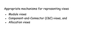
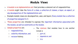
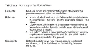
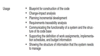
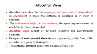
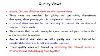
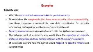
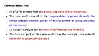
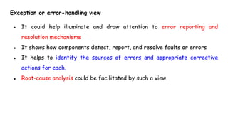


The document discusses documenting and implementing software architecture. It covers using views and notations to document architecture, including module, component-and-connector, and allocation views. It also discusses quality views that focus on specific attributes like security and communication. Architecture documentation serves educational, communication, and construction purposes.