This document discusses different types of solids and their properties. It provides steps for solving problems involving solids.
Group A solids like cylinders and prisms have bases and tops of the same shape. Group B solids like cones and pyramids have a point top called an apex.
Problems involving solids are solved in three steps: 1) assume the solid is standing on its plane of inclination, 2) draw front and top views considering the inclination axis, 3) draw final views considering any remaining inclinations.
Several example problems are provided and walked through step-by-step to demonstrate how to draw the projections of solids in different orientations. Freely suspended solids have their
Projection of solids - ENGINEERING DRAWING/GRAPHICSAbhishek Kandare
Projection of solids
HIS SLIDE CONTAINS WHOLE SYLLABUS OF ENGINEERING DRAWING/GRAPHICS. IT IS THE MOST SIMPLE AND INTERACTIVE WAY TO LEARN ENGINEERING DRAWING.SYLLABUS IS RELATED TO rajiv gandhi proudyogiki vishwavidyalaya / rajiv gandhi TECHNICAL UNIVERSITY ,BHOPAL.
Development of surfaces of solids -ENGINEERING DRAWING - RGPV,BHOPALAbhishek Kandare
Development of surfaces of solids
THIS SLIDE CONTAINS WHOLE SYLLABUS OF ENGINEERING DRAWING/GRAPHICS. IT IS THE MOST SIMPLE AND INTERACTIVE WAY TO LEARN ENGINEERING DRAWING.SYLLABUS IS RELATED TO rajiv gandhi proudyogiki vishwavidyalaya / rajiv gandhi TECHNICAL UNIVERSITY ,BHOPAL.
Projection of Planes and Section of SolidsParth Shah
Here's a PowerPoint presentation for you Engineering Graphics ALA, If your topic is 'Projection of Planes and Section of Solids'.
Keep track, We'll be uploading more.
Download the original presentation for animation and clear understanding. This Presentation describes the concepts of Engineering Drawing of VTU Syllabus. However same can also be used for learning drawing concepts. Please write to me for suggestions and criticisms here: hareeshang@gmail.com or visit this website for more details: www.hareeshang.wikifoundry.com.
This paper proposes the design and development of Arduino based solar charge controller with sun tracking using PWM technique. This PWM technique is employed using ATmega328P on Arduino board. The Arduino is used to charge a 12V battery using 10W solar panel. The main feature of this charge controller is to control the load. During day time when load is not connected the battery gets charged from solar panel. When battery reaches peak value of 14.7V charging current & further charging is interrupted by Arduino. An inbuilt analogue to digital converter is used to determine voltage of battery, solar panel and current drawn by the load. A solar tracking system is also implemented such that panel is always kept at right angle to incident radiation.
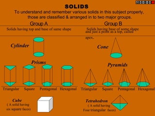
1. SOLIDS
To understand and remember various solids in this subject properly,
those are classified & arranged in to two major groups.
Group A
Solids having top and base of same shape
Cylinder
Prisms
Triangular Square Pentagonal Hexagonal
Cube
Triangular Square Pentagonal Hexagonal
Cone
Tetrahedron
Pyramids
( A solid having
six square faces)
( A solid having
Four triangular faces)
Group B
Solids having base of some shape
and just a point as a top, called
apex.
2. SOLIDS
Dimensional parameters of different solids.
Top
Rectangular
Face
Longer
Edge
Base
Edge
of
Base
Corner of
base
Corner of
base
Triangular
Face
Slant
Edge
Base
Apex
Square Prism Square Pyramid Cylinder Cone
Edge
of
Base
Base
Apex
Base
Generators
Imaginary lines
generating curved surface
of cylinder & cone.
Sections of solids( top & base not parallel) Frustum of cone & pyramids.
( top & base parallel to each other)
3. STEPS TO SOLVE PROBLEMS IN SOLIDS
Problem is solved in three steps:
STEP 1: ASSUME SOLID STANDING ON THE PLANE WITH WHICH IT IS MAKING INCLINATION.
( IF IT IS INCLINED TO HP, ASSUME IT STANDING ON HP)
( IF IT IS INCLINED TO VP, ASSUME IT STANDING ON VP)
IF STANDING ON HP - IT’S TV WILL BE TRUE SHAPE OF IT’S BASE OR TOP:
IF STANDING ON VP - IT’S FV WILL BE TRUE SHAPE OF IT’S BASE OR TOP.
BEGIN WITH THIS VIEW:
IT’S OTHER VIEW WILL BE A RECTANGLE ( IF SOLID IS CYLINDER OR ONE OF THE PRISMS):
IT’S OTHER VIEW WILL BE A TRIANGLE ( IF SOLID IS CONE OR ONE OF THE PYRAMIDS):
DRAW FV & TV OF THAT SOLID IN STANDING POSITION:
STEP 2: CONSIDERING SOLID’S INCLINATION ( AXIS POSITION ) DRAW IT’S FV & TV.
STEP 3: IN LAST STEP, CONSIDERING REMAINING INCLINATION, DRAW IT’S FINAL FV & TV.
AXIS
VERTICAL
AXIS
INCLINED HP
AXIS
INCLINED VP
AXIS
VERTICAL
AXIS
INCLINED HP
AXIS
INCLINED VP
AXIS TO VP
er
AXIS
INCLINED
VP
AXIS
INCLINED HP
AXIS TO VP
er AXIS
INCLINED
VP
AXIS
INCLINED HP
GENERAL PATTERN ( THREE STEPS ) OF SOLUTION:
GROUP B SOLID.
CONE
GROUP A SOLID.
CYLINDER
GROUP B SOLID.
CONE
GROUP A SOLID.
CYLINDER
Three steps
If solid is inclined to Hp
Three steps
If solid is inclined to Hp
Three steps
If solid is inclined to Vp
Study Next Twelve Problems and Practice them separately !!
Three steps
If solid is inclined to Vp
4. a
bd
c
1
24
3
X Ya b d c
1 2 4 3
a’
b’
c’
d’
1’
2’
3’
4’
450
4’
3’
2’
1’
d’
c’
b’
a’
4’
3’
2’
1’
d’
c’
b’
a’
350
a1
b1
c1
d1
1
2
3
4
Problem 3:
A cylinder 40 mm diameter and 50 mm
axis is resting on one point of a base
circle on Vp while it’s axis makes 450
with Vp and Fv of the axis 350
with Hp.
Draw projections..
Solution Steps:
Resting on Vp on one point of base, means inclined to Vp:
1.Assume it standing on Vp
2.It’s Fv will show True Shape of base & top( circle )
3.Draw 40mm dia. Circle as Fv & taking 50 mm axis project Tv.
( a Rectangle)
4.Name all points as shown in illustration.
5.Draw 2nd
Tv making axis 450
to xy And project it’s Fv above xy.
6.Make visible lines dark and hidden dotted, as per the procedure.
7.Then construct remaining inclination with Hp
( Fv of axis I.e. center line of view to xy as shown) & project final Tv.
5. Problem 5: A cube of 50 mm long
edges is so placed on Hp on one
corner that a body diagonal is
parallel to Hp and perpendicular to
Vp Draw it’s projections.
X Y
b
c
d
a
a’ d’ c’b’
a’
d’
c’
b’
a1
b1
d1
c1
a1
b1
d1
c1
1’
p’
p’
a’1
d’1
c’1
d’1
Solution Steps:
1.Assuming standing on Hp, begin with Tv,a square with all sides
equally inclined to xy.Project Fv and name all points of FV & TV.
2.Draw a body-diagonal joining c’ with 3’( This can become // to xy)
3.From 1’ drop a perpendicular on this and name it p’
4.Draw 2nd
Fv in which 1’-p’ line is vertical means c’-3’ diagonal
must be horizontal. .Now as usual project Tv..
6.In final Tv draw same diagonal is perpendicular to Vp as said in problem.
Then as usual project final FV.
1’3’ 1’
3’
6. FREELY SUSPENDED SOLIDS:
Positions of CG, on axis, from base, for different solids are shown below.
H
H/2
H/4
GROUP A SOLIDS
( Cylinder & Prisms)
GROUP B SOLIDS
( Cone & Pyramids)
CG
CG
7. a’ d’ c’b’
b
c
d
a
a’
d’
c’
b’a1
b
d1
c1
d’’
c’’
a’’
b’’
X Y1’
1’
1’
Problem 8:
A cube of 50 mm long edges is so placed
on Hp on one corner that a body diagonal
through this corner is perpendicular to Hp
and parallel to Vp Draw it’s three views.
Solution Steps:
1.Assuming it standing on Hp begin with Tv, a square of corner case.
2.Project corresponding Fv.& name all points as usual in both views.
3.Join a’1’ as body diagonal and draw 2nd
Fv making it vertical (I’ on xy)
4.Project it’s Tv drawing dark and dotted lines as per the procedure.
5.With standard method construct Left-hand side view.
( Draw a 450
inclined Line in Tv region ( below xy).
Project horizontally all points of Tv on this line and
reflect vertically upward, above xy.After this, draw
horizontal lines, from all points of Fv, to meet these
lines. Name points of intersections and join properly.
For dark & dotted lines
locate observer on left side of Fv as shown.)