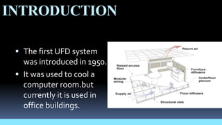
“FLUID DYNAMICS OF UNDER FLOOR AIR
DISTRIBUTION SYSTEM”
PRESENTED BY:-
Gurpreet singh
Uid- k10966
course – B.tech
Branch –mechanical
Year/Sem- 3rd/6th
PRESENTEDTO:-
Mr. Aditya Mishra
Assistant professor
Mechanical Deptt.
CAREER POINT UNIVERSITY, KOTA
MAJOR ASSIGNMENT OF RAC
CONTENT
1. Introduction.
2. Principle
3. Description.
4. Advantages.
5. Conclusion
6. Reference.
INTRODUCTION
 The first UFD system
was introduced in 1950.
 It was used to cool a
computer room.but
currently it is used in
office buildings.
PRINCIPLE
 UFAD systems capitalize on the natural stratification that occurs when
warm air rises due to thermal buoyancy.
 conditioned air stays in the lower, occupied part of the room, while heat
sources such as occupants and equipment generate thermal plumes, which
carry the warm air and heat source generated pollutants towards
the ceiling where they are exhausted through the return air ducts
SYSTEM DESCRIPTION
1.UFAD sys . 2.overhead
DESCRIPTION
 With UFAD systems, conditioned air from the air
handling unit (AHU) is ducted into the underfloor plenum
where it typically flows freely to the supply outlets.
Underfloor systems are generally configured to have a
relatively large number of smaller supply outlets, many in
close proximity to the building occupants, as compared
to a conventional overhead system.
ADVANTAGES
 Improved ventilation efficiency and indoor air
quality.
 Reduced energy use.
 Reduced floor-to-floor height in new
construction.
APPLICATION
 Underfloor air distribution is frequently used in office buildings, particularly
highly-reconfigurable and open plan offices where raised floors are desirable
for cable management
 UFAD is also common in command centers, IT data centers and Server
rooms that have large cooling loads from electronic equipment and
requirements for routing power and data cables.
REFERENCE
 Baines,W. D. 1975 Entrainment by a plume or jet at a
density interface. J. Fluid Mech. 68, 309{320.Baines,W. D. &
Turner, J.S. 1969Turbulent buoyant convection in a source
in a conffined region. J. Fluid Mech. 37, 51.
 ASHRAE. 1993. Handbook of Fundamentals,American
Society of Heating, Refrigerating, and AirConditioning
Engineers, Inc., Atlanta.ASHRAE. 2001. ASHRAE Handbook
of Fundamentals,American Society of Heating,
Refrigerating, andAir Conditioning Engineers, Inc., Atlanta.
THANK YOU

Ufad

  • 1.
    “FLUID DYNAMICS OFUNDER FLOOR AIR DISTRIBUTION SYSTEM” PRESENTED BY:- Gurpreet singh Uid- k10966 course – B.tech Branch –mechanical Year/Sem- 3rd/6th PRESENTEDTO:- Mr. Aditya Mishra Assistant professor Mechanical Deptt. CAREER POINT UNIVERSITY, KOTA MAJOR ASSIGNMENT OF RAC
  • 2.
    CONTENT 1. Introduction. 2. Principle 3.Description. 4. Advantages. 5. Conclusion 6. Reference.
  • 3.
    INTRODUCTION  The firstUFD system was introduced in 1950.  It was used to cool a computer room.but currently it is used in office buildings.
  • 4.
    PRINCIPLE  UFAD systemscapitalize on the natural stratification that occurs when warm air rises due to thermal buoyancy.  conditioned air stays in the lower, occupied part of the room, while heat sources such as occupants and equipment generate thermal plumes, which carry the warm air and heat source generated pollutants towards the ceiling where they are exhausted through the return air ducts
  • 5.
  • 6.
    DESCRIPTION  With UFADsystems, conditioned air from the air handling unit (AHU) is ducted into the underfloor plenum where it typically flows freely to the supply outlets. Underfloor systems are generally configured to have a relatively large number of smaller supply outlets, many in close proximity to the building occupants, as compared to a conventional overhead system.
  • 7.
    ADVANTAGES  Improved ventilationefficiency and indoor air quality.  Reduced energy use.  Reduced floor-to-floor height in new construction.
  • 8.
    APPLICATION  Underfloor airdistribution is frequently used in office buildings, particularly highly-reconfigurable and open plan offices where raised floors are desirable for cable management  UFAD is also common in command centers, IT data centers and Server rooms that have large cooling loads from electronic equipment and requirements for routing power and data cables.
  • 9.
    REFERENCE  Baines,W. D.1975 Entrainment by a plume or jet at a density interface. J. Fluid Mech. 68, 309{320.Baines,W. D. & Turner, J.S. 1969Turbulent buoyant convection in a source in a conffined region. J. Fluid Mech. 37, 51.  ASHRAE. 1993. Handbook of Fundamentals,American Society of Heating, Refrigerating, and AirConditioning Engineers, Inc., Atlanta.ASHRAE. 2001. ASHRAE Handbook of Fundamentals,American Society of Heating, Refrigerating, andAir Conditioning Engineers, Inc., Atlanta.
  • 10.