K R KRao - July 2014 1
Two-port Networks
K. Radhakrishna Rao
2.
K R KRao - July 2014 2
Two Port Networks
Two port network can be three terminal with one
terminal common to input and output ports. The
common terminal can be ground.
Or four terminals with only ground as common
terminal
We can have four variables two of which can be
independent and the other two become dependent.
If we further restrict our choice to one independent
variable at input port and one at output, we have four
types of representations possible. They are z, y and
h, g parameters.
3.
K R KRao - July 2014 3
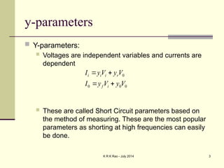
y-parameters
Y-parameters:
Voltages are independent variables and currents are
dependent
These are called Short Circuit parameters based on
the method of measuring. These are the most popular
parameters as shorting at high frequencies can easily
be done.
0
0
0
0
V
y
V
y
I
V
y
V
y
I
i
f
r
i
i
i
4.
K R KRao - July 2014 4
Passive network two-port parameters
r
f
r
f
r
f
r
f
g
g
h
h
z
z
y
y
,
,
5.
K R KRao - July 2014 5
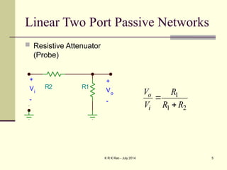
Linear Two Port Passive Networks
Resistive Attenuator
(Probe)
R2 R1
+
Vi
-
+
Vo
-
1
1 2
o
i
V R
V R R
6.
K R KRao - July 2014 6
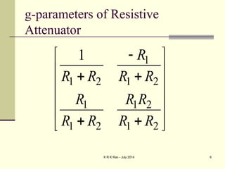
g-parameters of Resistive
Attenuator
1
1 2 1 2
1 1 2
1 2 1 2
1 R
R R R R
R R R
R R R R
7.
K R KRao - July 2014 7
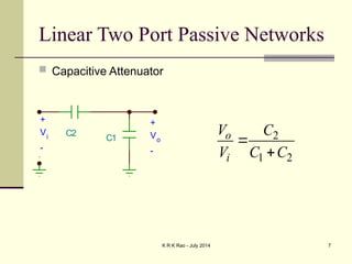
Linear Two Port Passive Networks
Capacitive Attenuator
C1
C2
+
Vi
-
+
Vo
-
2
1 2
o
i
V C
V C C
8.
K R KRao - July 2014 8
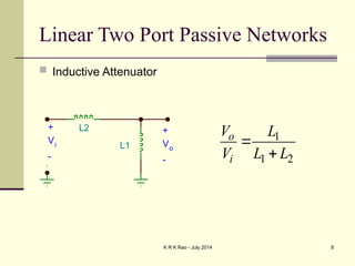
Linear Two Port Passive Networks
Inductive Attenuator
1
1 2
o
i
V L
V L L
L1
L2
+
Vi
-
+
Vo
-
9.
K R KRao - July 2014 9
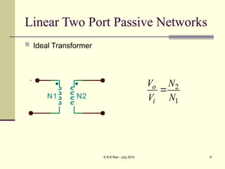
Linear Two Port Passive Networks
Ideal Transformer
2
1
o
i
V N
V N
N1 N2
10.
K R KRao - July 2014 10
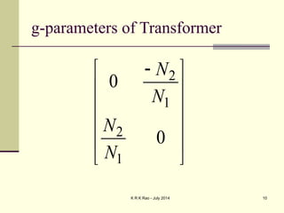
g-parameters of Transformer
2
1
2
1
0
0
N
N
N
N
11.
K R KRao - July 2014 11
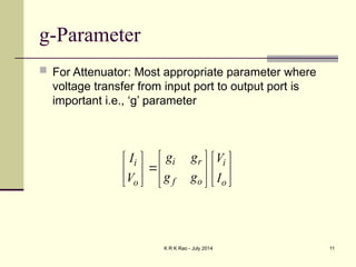
g-Parameter
For Attenuator: Most appropriate parameter where
voltage transfer from input port to output port is
important i.e., ‘g’ parameter
i r
i i
f o
o o
g g
I V
g g
V I
12.
K R KRao - July 2014 12
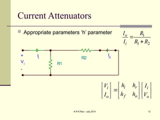
Current Attenuators
Appropriate parameters ‘h’ parameter
i r
i i
f o
o o
h h
V I
h h
I V
R1
R2
+
Vi
-
Io
Ii
1
1 2
o
i
I R
I R R
13.
K R KRao - July 2014 13
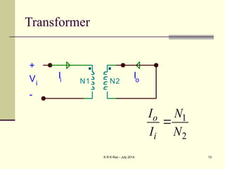
Transformer
1
2
o
i
I N
I N
N1 N2
+
Vi
-
Ii
Io
14.
K R KRao - July 2014 14
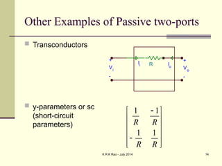
Other Examples of Passive two-ports
Transconductors
y-parameters or sc
(short-circuit
parameters)
R
+
Vi
-
+
Vo
-
Ii Io
1 1
1 1
R R
R R
15.
K R KRao - July 2014 15
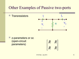
Other Examples of Passive two-ports
Transresistors
z-parameters or oc
(open-circuit
parameters)
R R
R R
R
+
Vi
-
+
Vo
-
Ii
Io
16.
K R KRao - July 2014 16
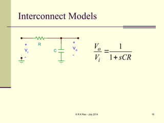
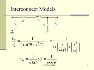
Interconnect Models
1
1
o
i
V
V sCR
R
C
+
Vo
-
+
Vi
-
17.
K R KRao - July 2014 17
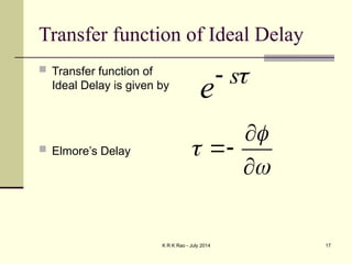
Transfer function of Ideal Delay
Transfer function of
Ideal Delay is given by
Elmore’s Delay
s
e
18.
K R KRao - July 2014 18
Interconnect Models
2
1
1
o
i
V
V sCR s LC
2
2
1
1
o o
s s
Q
1 1
;
o
o
Q
CR
LC
R
C
L +
Vo
-
+
Vi
-
19.
K R KRao - July 2014 19
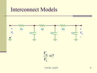
Interconnect Models
?
o
i
V
V
R1
C1
R2
C2
R3
C3
+
Vo
-
+
Vi
-
20.
K R KRao - July 2014 20
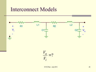
Interconnect Models
?
o
i
V
V
R1
C1
L1
R2
C2
L2
+
Vo
-
+
Vi
-
21.
K R KRao - July 2014 21
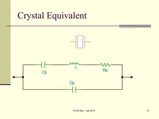
Crystal Equivalent
Cs
L
Rs
Cp
22.
K R KRao - July 2014 22
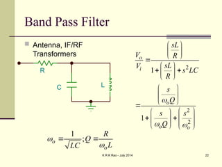
Band Pass Filter
Antenna, IF/RF
Transformers
2
2
2
1
1
o
i
o
o o
sL
V R
sL
V
s LC
R
s
Q
s s
Q
R
C L
1
;
o
o
R
Q
L
LC
23.
K R KRao - July 2014 23
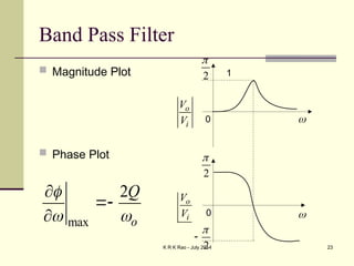
Band Pass Filter
Magnitude Plot
Phase Plot
2
2
0
0
2
o
i
V
V
o
i
V
V
1
max
2
o
Q
24.
K R KRao - July 2014 24
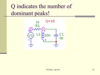
Q indicates the number of
dominant peaks!
25.
K R KRao - July 2014 25
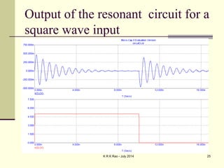
Output of the resonant circuit for a
square wave input
26.
K R KRao - July 2014 26
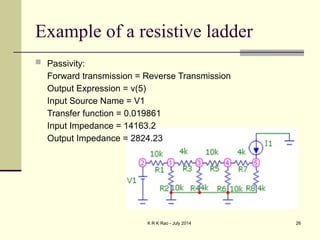
Example of a resistive ladder
Passivity:
Forward transmission = Reverse Transmission
Output Expression = v(5)
Input Source Name = V1
Transfer function = 0.019861
Input Impedance = 14163.2
Output Impedance = 2824.23
27.
K R KRao - July 2014 27
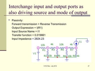
Interchange input and output ports as
also driving source and mode of output
Passivity:
Forward transmission = Reverse Transmission
Output Expression = I(R1)
Input Source Name = I1
Transfer function = 0.019861
Input Impedance = 2824.23
28.
K R KRao - July 2014 28
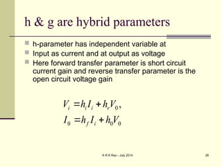
h & g are hybrid parameters
h-parameter has independent variable at
Input as current and at output as voltage
Here forward transfer parameter is short circuit
current gain and reverse transfer parameter is the
open circuit voltage gain
0
0
0
0 ,
V
h
I
h
I
V
h
I
h
V
i
f
r
i
i
i