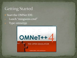
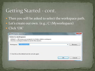
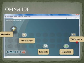
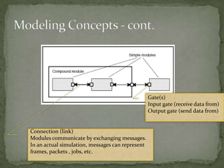
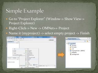
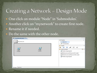
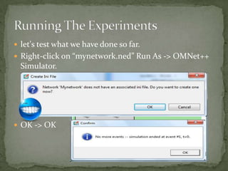
By
Mohammed Amer Al-Batati

         2012
 Start the OMNet IDE:
1. Lunch “mingwenv.cmd”
2. Type: omnetpp
 Then you will be asked to select the workspace path.
 Let’s create our own. (e.g.; C:Myworkspace)
 Click ‘OK’
Overview

                                            Workbench
           What's New


                        Tutorials   Migration
 An  OMNeT++ model consists of modules that
  communicate with message passing.
 Simple modules can be grouped into compound
  modules and so forth.
 The number of hierarchy levels is unlimited.
Gate(s)
                                                  Input gate (receive data from)
                                                  Output gate (send data from)


Connection (link)
Modules communicate by exchanging messages.
In an actual simulation, messages can represent
frames, packets , jobs, etc.
 Go to “Project Explorer” (Window-> Show View->
  Project Explorer)
 Right-Click-> New -> OMNet++ Project
 Name it (myproject) -> select empty project -> Finish
 Right-Click on “myproject” -> New -> Simple Module
 Name it (Node.ned) -> A simple module -> Finish
 Double Click on “Node.ned”.
 A dual-mode (Design and Source) NED editor is
 opened.
 Double Click on “Node.ned”.
 A dual-mode (Design and Source) NED editor is
 opened.
 For now, let our Node with only two gates: input and
    output gates.
   Use keyword “gates” followed by “:” to define gates.
   Use keyword “input” for input gates.
   Use keyword “output” for output gates.
   Don’t forget semi-colons or to save your file.
 Go back to “Design” view.
 By Right-click on Node module, you can modify the
  module properties (e.g.; base, icon and polygon).
 Let’s change the icon.
 Let’s create a network with two nodes (node1 and
  node2) connected to each other.
 Right-Click on “myproject” -> New -> Network
 Name it (mynetwork.ned) -> An empty network ->
  Finish.
 Still with NED editor, so it can be done using either
  Design or Source mode.
 One click on module “Node” in ‘Submodules’.
 Another click on “mynetwork” to create first node.
 Rename it if needed.
 Do the same with the other node.
 Connect them together by using “Connection”, which
  can be founded in Palette.
 There are three types of channels:


 Activate “Connection” by clicking on it.
 Connect Node1 with Node2 by clicking Node1 first
  then Node2. (From node1 to Node2)
 Do the same with Node 2.
 By opening the Source mode we will find:


                                      CTRL+SHIFT+O
                                      To import needed packages.


                                      CTRL+SHIFT+F
                                      To reformat the NED file.


               CTRL+SPACE
               When help is needed.
 let's test what we have done so far.
 Right-click on “mynetwork.ned” Run As -> OMNet++
  Simulator.


 OK -> OK

Tutorial 3 getting started with omnet

  • 1.
  • 2.
     Start theOMNet IDE: 1. Lunch “mingwenv.cmd” 2. Type: omnetpp
  • 3.
     Then youwill be asked to select the workspace path.  Let’s create our own. (e.g.; C:Myworkspace)  Click ‘OK’
  • 4.
    Overview Workbench What's New Tutorials Migration
  • 5.
     An OMNeT++ model consists of modules that communicate with message passing.  Simple modules can be grouped into compound modules and so forth.  The number of hierarchy levels is unlimited.
  • 6.
    Gate(s) Input gate (receive data from) Output gate (send data from) Connection (link) Modules communicate by exchanging messages. In an actual simulation, messages can represent frames, packets , jobs, etc.
  • 7.
     Go to“Project Explorer” (Window-> Show View-> Project Explorer)  Right-Click-> New -> OMNet++ Project  Name it (myproject) -> select empty project -> Finish
  • 8.
     Right-Click on“myproject” -> New -> Simple Module  Name it (Node.ned) -> A simple module -> Finish
  • 9.
     Double Clickon “Node.ned”.  A dual-mode (Design and Source) NED editor is opened.
  • 10.
     Double Clickon “Node.ned”.  A dual-mode (Design and Source) NED editor is opened.
  • 11.
     For now,let our Node with only two gates: input and output gates.  Use keyword “gates” followed by “:” to define gates.  Use keyword “input” for input gates.  Use keyword “output” for output gates.  Don’t forget semi-colons or to save your file.
  • 12.
     Go backto “Design” view.  By Right-click on Node module, you can modify the module properties (e.g.; base, icon and polygon).  Let’s change the icon.
  • 13.
     Let’s createa network with two nodes (node1 and node2) connected to each other.  Right-Click on “myproject” -> New -> Network  Name it (mynetwork.ned) -> An empty network -> Finish.  Still with NED editor, so it can be done using either Design or Source mode.
  • 14.
     One clickon module “Node” in ‘Submodules’.  Another click on “mynetwork” to create first node.  Rename it if needed.  Do the same with the other node.
  • 15.
     Connect themtogether by using “Connection”, which can be founded in Palette.  There are three types of channels:  Activate “Connection” by clicking on it.  Connect Node1 with Node2 by clicking Node1 first then Node2. (From node1 to Node2)  Do the same with Node 2.
  • 16.
     By openingthe Source mode we will find: CTRL+SHIFT+O To import needed packages. CTRL+SHIFT+F To reformat the NED file. CTRL+SPACE When help is needed.
  • 17.
     let's testwhat we have done so far.  Right-click on “mynetwork.ned” Run As -> OMNet++ Simulator.  OK -> OK