SlideShare a Scribd company logo
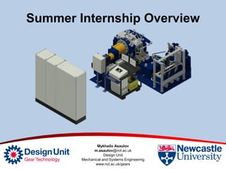
Summer Internship Overview
Mykhailo Asaulov
m.asaulov@ncl.ac.uk
Design Unit
Mechanical and Systems Engineering
www.ncl.ac.uk/gears
Contents
• Bearing Test Rig:
– Transferring the CAD model / Engineering Drawings into the new DU BOM.
– Assisting technicians in assembly of the Bearing Test Rig.
– Organising ED / Datasheets / Calibration documents.
• Adaptor hand calculations for 91.5 Gear Test Rig:
– Required quantity and diameter of bolts essential to withstand the worst
case conditions.
– Axial load induced by helical gears. Conical effective clamp diameter.
– Maximum deflection of adaptor caused by the axial load.
• Validation of hand calculations by applying ANSYS simulation
software:
– Adaptor 3D model
– Adaptor 2D model
– Assembly 3D model
Bearing Test Rig:
• Improvements / Optimisations of assembly sequence.
• Checking all engineering drawings. Updating and modifying
them where it was required.
• Completing “Lubrication Circuit ASY” and designing
“Trimming Circuit ASY” by applying Tube & Pipe Design.
Lubrication
Circuit
Trimming
Circuit
Bearing Test Rig:
• Understanding the difference between assembly of different components in
real life compare to CAD model virtual assembly.
• Learning how to use various equipment.
SKF Induction
Heater
SKF Test Bearing
Torque multiplier
Ration 25:1
Max 6000 Nm
Bearing Test Rig:
• Creating Multilevel BOM for engineering drawings folder to make it easy to
follow the assembly structure and in case of manufacturing process to know
exactly how many components are required for each sub assembly.
Adaptor hand calculations
for 91.5 Gear Test Rig:
Bolts Fitted in Large Clearance Holes:
• Initial conditions: max torque = 1500 Nm, friction = 0.125, S.F = 2.
• Results: 10 bolts of M12 with Preload = 36.2 kN or 12 bolts of M10 with
Preload = 30.1 kN.
Adaptor hand calculations
for 91.5 Gear Test Rig:
Cone Diameter:
• Result: 31 mm
Helical Gears:
• Result: Axial load on
Pinion = 27.7 kN
Maximum Deflection:
• Results:
– www.roymech.co.uk – y = 0.02226 mm
– ROARK’S Formulas – y = 0.02387 mm
Adaptor hand calculations
for 91.5 Gear Test Rig:
Spline
Coupling
27.7 kN
Gear
Shaft
Adaptor
M12 Socket
Head Cap Screw
Deflection
y [mm]
ANSYS Simulation
Adaptor 3D model
• Elements - Tetrahedron
• Results:
– Maximum deformation = 0.013886 mm
Elements Deformation [mm]
1775 0.011667
7980 0.012859
15681 0.013363
38424 0.013607
85953 0.013710
166054 0.013814
313970 0.013886
27.7 kN
Fixed
Support
( Ø Cone)
ANSYS Simulation
Adaptor 2D model
• Elements – Hex-Dominant
• Results:
– Maximum deformation = 0.013358 mm
Elements Deformation [mm]
123 0.012655
230 0.013014
516 0.013147
2043 0.013261
8085 0.013325
32416 0.013358
27.7 kN
Fixed
Support
( Ø Cone)
Assembly 3D model
• Elements - Tetrahedron
• Moment was applied along with others forces.
• Results:
– Maximum deformation = 0.013547 mm
ANSYS Simulation
Moment
1500 Nm Fixed
Support
2x 27.7 kN
Bonded
connections
Elements Deformation [mm]
7294 0.01245
206148 0.013417
280764 0.013516
369954 0.013547
Conclusion
• Bearing Test Rig:
– Fully transferred into DU BOM.
– Ready for commercial usage.
• Coupling Adaptor:
– 10 Bolts of M12
– Hand calculation – deformation = 0.02387 mm
– ANSYS 3D model = 0.013886 mm
– ANSYS 2D model = 0.013358 mm
– ANSYS ASY 3D model = 0.013547 mm
QUESTIONS?

More Related Content

What's hot

Senior Design Final Presentation
Senior Design Final PresentationSenior Design Final Presentation
Senior Design Final Presentationguest05f90e
 
Kinetics of a particle
Kinetics of a particleKinetics of a particle
Kinetics of a particlearu t
 
The Butterfly Valve Assembly Pro E vaibhavkumar vaghani
The Butterfly Valve Assembly Pro E vaibhavkumar vaghaniThe Butterfly Valve Assembly Pro E vaibhavkumar vaghani
The Butterfly Valve Assembly Pro E vaibhavkumar vaghaniVaibhavkumar Vaghani
 
Autocad - The shock Assembly - Vaibhavkumar Vaghani
Autocad - The shock Assembly - Vaibhavkumar VaghaniAutocad - The shock Assembly - Vaibhavkumar Vaghani
Autocad - The shock Assembly - Vaibhavkumar VaghaniVaibhavkumar Vaghani
 
Vibrating feeder
Vibrating feederVibrating feeder
Vibrating feederEvita Lee
 
Unit i
Unit iUnit i
Unit iSTEN
 
Inertia dynamics shaftmtdbrake310_specsheet
Inertia dynamics shaftmtdbrake310_specsheetInertia dynamics shaftmtdbrake310_specsheet
Inertia dynamics shaftmtdbrake310_specsheetElectromate
 
Portfolio_Huizhe_Zhao_6-19-2016
Portfolio_Huizhe_Zhao_6-19-2016Portfolio_Huizhe_Zhao_6-19-2016
Portfolio_Huizhe_Zhao_6-19-2016Huizhe (Lucy) Zhao
 
Kemet Webinar - Caps for 48V Boardnet application
Kemet Webinar - Caps for 48V Boardnet applicationKemet Webinar - Caps for 48V Boardnet application
Kemet Webinar - Caps for 48V Boardnet applicationAlexanderNebel1
 
Ms l shape angle wholesale trader from kolkata
Ms l shape angle wholesale trader from kolkataMs l shape angle wholesale trader from kolkata
Ms l shape angle wholesale trader from kolkataShree Ji Steel Corporation
 
C:\documents and settings\mewar\desktop\bearing\geared exciter
C:\documents and settings\mewar\desktop\bearing\geared exciterC:\documents and settings\mewar\desktop\bearing\geared exciter
C:\documents and settings\mewar\desktop\bearing\geared exciterguest03ca43c
 
Dynamics of an IC Engine Valvetrain
Dynamics of an IC Engine ValvetrainDynamics of an IC Engine Valvetrain
Dynamics of an IC Engine ValvetrainNARAYAN SUSANGE
 
Segment Presentation RES Rail Equipment
Segment Presentation RES Rail EquipmentSegment Presentation RES Rail Equipment
Segment Presentation RES Rail EquipmentStephen Furze
 

What's hot (19)

Senior Design Final Presentation
Senior Design Final PresentationSenior Design Final Presentation
Senior Design Final Presentation
 
Kinetics of a particle
Kinetics of a particleKinetics of a particle
Kinetics of a particle
 
The Butterfly Valve Assembly Pro E vaibhavkumar vaghani
The Butterfly Valve Assembly Pro E vaibhavkumar vaghaniThe Butterfly Valve Assembly Pro E vaibhavkumar vaghani
The Butterfly Valve Assembly Pro E vaibhavkumar vaghani
 
Autocad - The shock Assembly - Vaibhavkumar Vaghani
Autocad - The shock Assembly - Vaibhavkumar VaghaniAutocad - The shock Assembly - Vaibhavkumar Vaghani
Autocad - The shock Assembly - Vaibhavkumar Vaghani
 
Vibrating feeder
Vibrating feederVibrating feeder
Vibrating feeder
 
Unit i
Unit iUnit i
Unit i
 
Inertia dynamics shaftmtdbrake310_specsheet
Inertia dynamics shaftmtdbrake310_specsheetInertia dynamics shaftmtdbrake310_specsheet
Inertia dynamics shaftmtdbrake310_specsheet
 
Portfolio_Huizhe_Zhao_6-19-2016
Portfolio_Huizhe_Zhao_6-19-2016Portfolio_Huizhe_Zhao_6-19-2016
Portfolio_Huizhe_Zhao_6-19-2016
 
Hmm qc project
Hmm qc project Hmm qc project
Hmm qc project
 
Kemet Webinar - Caps for 48V Boardnet application
Kemet Webinar - Caps for 48V Boardnet applicationKemet Webinar - Caps for 48V Boardnet application
Kemet Webinar - Caps for 48V Boardnet application
 
Diesel engine-crusher
Diesel engine-crusherDiesel engine-crusher
Diesel engine-crusher
 
Ms l shape angle wholesale trader from kolkata
Ms l shape angle wholesale trader from kolkataMs l shape angle wholesale trader from kolkata
Ms l shape angle wholesale trader from kolkata
 
Cap Torque Tester by ACMAS Technologies Pvt Ltd.
Cap Torque Tester by ACMAS Technologies Pvt Ltd.Cap Torque Tester by ACMAS Technologies Pvt Ltd.
Cap Torque Tester by ACMAS Technologies Pvt Ltd.
 
Npb
NpbNpb
Npb
 
C:\documents and settings\mewar\desktop\bearing\geared exciter
C:\documents and settings\mewar\desktop\bearing\geared exciterC:\documents and settings\mewar\desktop\bearing\geared exciter
C:\documents and settings\mewar\desktop\bearing\geared exciter
 
Cancamos giratorios gunnebo
Cancamos giratorios gunneboCancamos giratorios gunnebo
Cancamos giratorios gunnebo
 
abc123
abc123abc123
abc123
 
Dynamics of an IC Engine Valvetrain
Dynamics of an IC Engine ValvetrainDynamics of an IC Engine Valvetrain
Dynamics of an IC Engine Valvetrain
 
Segment Presentation RES Rail Equipment
Segment Presentation RES Rail EquipmentSegment Presentation RES Rail Equipment
Segment Presentation RES Rail Equipment
 

Viewers also liked (16)

每日靈修0507
每日靈修0507每日靈修0507
每日靈修0507
 
Group 1_Home Health Care
Group 1_Home Health CareGroup 1_Home Health Care
Group 1_Home Health Care
 
每日靈修0717
每日靈修0717每日靈修0717
每日靈修0717
 
Televisionenperuypuno
TelevisionenperuypunoTelevisionenperuypuno
Televisionenperuypuno
 
每日靈修0606
每日靈修0606每日靈修0606
每日靈修0606
 
每日靈修0430
每日靈修0430每日靈修0430
每日靈修0430
 
每日靈修0613
每日靈修0613每日靈修0613
每日靈修0613
 
Argie bond quant track record
Argie bond quant track recordArgie bond quant track record
Argie bond quant track record
 
每日靈修0616
每日靈修0616每日靈修0616
每日靈修0616
 
IILP Review 2014 - Decline in African America Partners (2)
IILP Review 2014 - Decline in African America Partners (2)IILP Review 2014 - Decline in African America Partners (2)
IILP Review 2014 - Decline in African America Partners (2)
 
每日靈修0713
每日靈修0713每日靈修0713
每日靈修0713
 
8 ano capítulo 9
8 ano capítulo 98 ano capítulo 9
8 ano capítulo 9
 
Rasil Warnakulasooriya Recommendation
Rasil Warnakulasooriya RecommendationRasil Warnakulasooriya Recommendation
Rasil Warnakulasooriya Recommendation
 
4
44
4
 
Ghosted Illustration from 3D CAD
Ghosted Illustration from 3D CADGhosted Illustration from 3D CAD
Ghosted Illustration from 3D CAD
 
Questões comentadas - Técnico em Radiologia EMSERH
Questões comentadas - Técnico em Radiologia EMSERHQuestões comentadas - Técnico em Radiologia EMSERH
Questões comentadas - Técnico em Radiologia EMSERH
 

Similar to Presentation - Summer Internship DU M.Asaulov

225081112-Design Project PPT-2023.pptx
225081112-Design Project PPT-2023.pptx225081112-Design Project PPT-2023.pptx
225081112-Design Project PPT-2023.pptxWilliamJayaPrakash
 
Minimization of stresses in a helical gear by solid modelling in creo software
Minimization of stresses in a helical gear by solid modelling in creo softwareMinimization of stresses in a helical gear by solid modelling in creo software
Minimization of stresses in a helical gear by solid modelling in creo softwareDenil Patel, MBA
 
CapstoneFinalReport-McHugh
CapstoneFinalReport-McHughCapstoneFinalReport-McHugh
CapstoneFinalReport-McHughJoshua McHugh
 
Design of an in wheel suspension with automatic camber
Design of an in wheel suspension with automatic camberDesign of an in wheel suspension with automatic camber
Design of an in wheel suspension with automatic camberSameer Shah
 
357502268-C-clamp-ppt.pptx
357502268-C-clamp-ppt.pptx357502268-C-clamp-ppt.pptx
357502268-C-clamp-ppt.pptxRajeshJavali2
 
Structural analysis of a brake disc.pptm
Structural analysis of a brake disc.pptmStructural analysis of a brake disc.pptm
Structural analysis of a brake disc.pptmVedprakash Arya
 
Design and Construction of a Connecting rod
Design and Construction of a Connecting rodDesign and Construction of a Connecting rod
Design and Construction of a Connecting rodFaisal Niloy
 
Design & Construction of a Connecting rod
Design & Construction of a Connecting rodDesign & Construction of a Connecting rod
Design & Construction of a Connecting rodFaisal Niloy
 
Three phase BLDC motor
Three phase BLDC motorThree phase BLDC motor
Three phase BLDC motorAnoop S
 
DESIGN AND FABRICATION OF FATIGUE TESTING MACHINE
DESIGN AND FABRICATION OF FATIGUE TESTING MACHINEDESIGN AND FABRICATION OF FATIGUE TESTING MACHINE
DESIGN AND FABRICATION OF FATIGUE TESTING MACHINERakesh J M
 
Kesavulu_summer intern project ppt
Kesavulu_summer intern project pptKesavulu_summer intern project ppt
Kesavulu_summer intern project pptKesava S
 
Simulation of Deep-Drawing Process of Large Panels
Simulation of Deep-Drawing Process of Large PanelsSimulation of Deep-Drawing Process of Large Panels
Simulation of Deep-Drawing Process of Large Panelstheijes
 

Similar to Presentation - Summer Internship DU M.Asaulov (20)

225081112-Design Project PPT-2023.pptx
225081112-Design Project PPT-2023.pptx225081112-Design Project PPT-2023.pptx
225081112-Design Project PPT-2023.pptx
 
Suspension optimization ppt
Suspension optimization pptSuspension optimization ppt
Suspension optimization ppt
 
QRM Project
QRM ProjectQRM Project
QRM Project
 
Minimization of stresses in a helical gear by solid modelling in creo software
Minimization of stresses in a helical gear by solid modelling in creo softwareMinimization of stresses in a helical gear by solid modelling in creo software
Minimization of stresses in a helical gear by solid modelling in creo software
 
project ppt
project pptproject ppt
project ppt
 
CapstoneFinalReport-McHugh
CapstoneFinalReport-McHughCapstoneFinalReport-McHugh
CapstoneFinalReport-McHugh
 
Design of an in wheel suspension with automatic camber
Design of an in wheel suspension with automatic camberDesign of an in wheel suspension with automatic camber
Design of an in wheel suspension with automatic camber
 
B012460814
B012460814B012460814
B012460814
 
connecting rod
connecting rodconnecting rod
connecting rod
 
357502268-C-clamp-ppt.pptx
357502268-C-clamp-ppt.pptx357502268-C-clamp-ppt.pptx
357502268-C-clamp-ppt.pptx
 
Structural analysis of a brake disc.pptm
Structural analysis of a brake disc.pptmStructural analysis of a brake disc.pptm
Structural analysis of a brake disc.pptm
 
Final ppt (26-06-2014)
Final ppt (26-06-2014)Final ppt (26-06-2014)
Final ppt (26-06-2014)
 
Design and Construction of a Connecting rod
Design and Construction of a Connecting rodDesign and Construction of a Connecting rod
Design and Construction of a Connecting rod
 
Design & Construction of a Connecting rod
Design & Construction of a Connecting rodDesign & Construction of a Connecting rod
Design & Construction of a Connecting rod
 
Three phase BLDC motor
Three phase BLDC motorThree phase BLDC motor
Three phase BLDC motor
 
DESIGN AND FABRICATION OF FATIGUE TESTING MACHINE
DESIGN AND FABRICATION OF FATIGUE TESTING MACHINEDESIGN AND FABRICATION OF FATIGUE TESTING MACHINE
DESIGN AND FABRICATION OF FATIGUE TESTING MACHINE
 
Kesavulu_summer intern project ppt
Kesavulu_summer intern project pptKesavulu_summer intern project ppt
Kesavulu_summer intern project ppt
 
Gearbox design
Gearbox designGearbox design
Gearbox design
 
Co-simulation with Siemens NX - David van Os, Ugent
Co-simulation with Siemens NX - David van Os, UgentCo-simulation with Siemens NX - David van Os, Ugent
Co-simulation with Siemens NX - David van Os, Ugent
 
Simulation of Deep-Drawing Process of Large Panels
Simulation of Deep-Drawing Process of Large PanelsSimulation of Deep-Drawing Process of Large Panels
Simulation of Deep-Drawing Process of Large Panels
 

Presentation - Summer Internship DU M.Asaulov

  • 1. Summer Internship Overview Mykhailo Asaulov m.asaulov@ncl.ac.uk Design Unit Mechanical and Systems Engineering www.ncl.ac.uk/gears
  • 2. Contents • Bearing Test Rig: – Transferring the CAD model / Engineering Drawings into the new DU BOM. – Assisting technicians in assembly of the Bearing Test Rig. – Organising ED / Datasheets / Calibration documents. • Adaptor hand calculations for 91.5 Gear Test Rig: – Required quantity and diameter of bolts essential to withstand the worst case conditions. – Axial load induced by helical gears. Conical effective clamp diameter. – Maximum deflection of adaptor caused by the axial load. • Validation of hand calculations by applying ANSYS simulation software: – Adaptor 3D model – Adaptor 2D model – Assembly 3D model
  • 3. Bearing Test Rig: • Improvements / Optimisations of assembly sequence. • Checking all engineering drawings. Updating and modifying them where it was required. • Completing “Lubrication Circuit ASY” and designing “Trimming Circuit ASY” by applying Tube & Pipe Design. Lubrication Circuit Trimming Circuit
  • 4. Bearing Test Rig: • Understanding the difference between assembly of different components in real life compare to CAD model virtual assembly. • Learning how to use various equipment. SKF Induction Heater SKF Test Bearing Torque multiplier Ration 25:1 Max 6000 Nm
  • 5. Bearing Test Rig: • Creating Multilevel BOM for engineering drawings folder to make it easy to follow the assembly structure and in case of manufacturing process to know exactly how many components are required for each sub assembly.
  • 6. Adaptor hand calculations for 91.5 Gear Test Rig: Bolts Fitted in Large Clearance Holes: • Initial conditions: max torque = 1500 Nm, friction = 0.125, S.F = 2. • Results: 10 bolts of M12 with Preload = 36.2 kN or 12 bolts of M10 with Preload = 30.1 kN.
  • 7. Adaptor hand calculations for 91.5 Gear Test Rig: Cone Diameter: • Result: 31 mm Helical Gears: • Result: Axial load on Pinion = 27.7 kN
  • 8. Maximum Deflection: • Results: – www.roymech.co.uk – y = 0.02226 mm – ROARK’S Formulas – y = 0.02387 mm Adaptor hand calculations for 91.5 Gear Test Rig: Spline Coupling 27.7 kN Gear Shaft Adaptor M12 Socket Head Cap Screw Deflection y [mm]
  • 9. ANSYS Simulation Adaptor 3D model • Elements - Tetrahedron • Results: – Maximum deformation = 0.013886 mm Elements Deformation [mm] 1775 0.011667 7980 0.012859 15681 0.013363 38424 0.013607 85953 0.013710 166054 0.013814 313970 0.013886 27.7 kN Fixed Support ( Ø Cone)
  • 10. ANSYS Simulation Adaptor 2D model • Elements – Hex-Dominant • Results: – Maximum deformation = 0.013358 mm Elements Deformation [mm] 123 0.012655 230 0.013014 516 0.013147 2043 0.013261 8085 0.013325 32416 0.013358 27.7 kN Fixed Support ( Ø Cone)
  • 11. Assembly 3D model • Elements - Tetrahedron • Moment was applied along with others forces. • Results: – Maximum deformation = 0.013547 mm ANSYS Simulation Moment 1500 Nm Fixed Support 2x 27.7 kN Bonded connections Elements Deformation [mm] 7294 0.01245 206148 0.013417 280764 0.013516 369954 0.013547
  • 12. Conclusion • Bearing Test Rig: – Fully transferred into DU BOM. – Ready for commercial usage. • Coupling Adaptor: – 10 Bolts of M12 – Hand calculation – deformation = 0.02387 mm – ANSYS 3D model = 0.013886 mm – ANSYS 2D model = 0.013358 mm – ANSYS ASY 3D model = 0.013547 mm