SlideShare a Scribd company logo
SPE-174659-MS
The Influence of Chemical EOR on Produced Water Separation and Quality
Anton Kaiser, Alan White, Andi Lukman, Istiyarso I, Martin Gernand, Hadi ShamsiJazeyi, Jonathan Wylde,
and Lourdes Alvarez, Clariant Oil Services
Copyright 2015, Society of Petroleum Engineers
This paper was prepared for presentation at the SPE Enhanced Oil Recovery Conference held in Kuala Lumpur, Malaysia, 11–13 August 2015.
This paper was selected for presentation by an SPE program committee following review of information contained in an abstract submitted by the author(s). Contents
of the paper have not been reviewed by the Society of Petroleum Engineers and are subject to correction by the author(s). The material does not necessarily reflect
any position of the Society of Petroleum Engineers, its officers, or members. Electronic reproduction, distribution, or storage of any part of this paper without the written
consent of the Society of Petroleum Engineers is prohibited. Permission to reproduce in print is restricted to an abstract of not more than 300 words; illustrations may
not be copied. The abstract must contain conspicuous acknowledgment of SPE copyright.
Abstract
The use of alkaline surfactant polymer flooding techniques is becoming more commonplace, particularly
in projects where heavier and more viscous crude oil is produced. While the efficacy of increasing
recovery factors cannot be disputed, often there is little consideration given to the implications of these
EOR chemicals breaking through into producer wells and entering the produced water handling system.
The impact caused by EOR chemical breakthrough can be varied, but most commonly the efficacy of
oil/water separation is seriously affected. The contribution that EOR chemicals can have on reservoir
souring is often underestimated, as is the effect they can have upon standard production chemicals such
as scale and corrosion inhibitors. The following paper discusses the oil in water and water in oil emulsion
issues during an alkaline surfactant polymer flooding pilot in Asia.
Introduction
During the application of chemical enhanced oil recovery (EOR) floods, breakthrough of the injection
chemicals periodically occurs resulting in stable emulsions. It is generally challenging to predict exactly
when chemical breakthrough will occur, and flood designs try to eliminate this unwanted event from
occurring. Some EOR recommendations use a combination of surfactant and polymer (SP), alkaline,
surfactant and polymer (ASP), and variations on these two themes. In the event of chemical breakthrough,
it is critical to have processes in place that can handle the ever changing conditions that evolve during the
course of crude oil recovery. The emulsions from such floods can yield both stable water-in-oil (normal)
and oil-in-water (reverse) emulsions particularly if the return of injection chemicals is higher than
expected.
ASP flooding involves injection of a predetermined volume of ASP chemicals into the reservoir, in
order to enhance oil recovery through reduction of Residual Oil Saturation (ROS) and enhancing sweep
efficiency of the system. The surfactant, with its Interfacial Tension (IFT) reduction effects, reduces the
ROS of the system, and the polymer, through its mobility control effects, increases sweep efficiency.
Alkali protects the surfactant from being adsorbed, and also supplements the IFT reduction process,
through saponification of the natural acids in the oil. ASP flooding has proved to increase oil recovery in
many field trials globally. Several ASP pilots of different scales are reported to have yielded net
incremental recovery factors in the range of 15% to 25% over waterflooding.
All physical factors listed previously that enhance oil recovery, can also greatly contribute to the
formation of very stable emulsions which are ultimately quite different from naturally occurring emul-
sions which tend to be stabilized by components such as asphaltenes and resins. Traditional emulsion
breakers are often not effective on emulsions created by chemical floods. Like any emulsion, these
induced (i.e. basically synthetic) EOR-based emulsions need to be resolved or broken. Producing dry oil
and clean water are requirements that all producers must achieve. Dry oil is needed to meet pipeline and
various other transportation specifications, whilst clean water is required to meet environment regulations
and operators’ own production needs.
The following paper describes the emulsion breaker selection as part of the final stages of commis-
sioning an ASP EOR pilot project in Asia. The main separation study was done at the EOR lab of the EOR
pilot plant. Further work was performed at Clariant’s global oilfield development labs.
Field and Treatment System
The production volumes of the current process system are 160,000 BOPD and 206,000 BWPD. Most of
the 100ϩ wells are produced using jet pumps driven by produced water or power water; this increases the
water handling to 400,000 BWPD. Only 20 of the total producing wells are ESP.
The crude oil has an API of 31° and a Pour Point of 35 to 38°C; the Wax Appearance Temperature is
51°C. The production header temperature at the different well pads is between 48 and 67°C. Emulsion
breaker chemical is injected to the production header at the well pads and also at the trains.
There are 5 production trains, each consisting of a slug catcher (inlet 70% water cut (WC), outlet
10%WC), a heater (outlet approx. 85°C) and a production separator (outlet 10%WC); all trains feed three
settling tanks. Furthermore, there are electrical dehydrators downstream of each of these tanks. The total
retention time for the water separation is about 10 hours.
The biggest challenge in the process is the quality of the separated water. Due to high throughput in
the 5 trains the interface level of the slug catchers are low resulting in high residual oil in water (OiW)
levels (~200ppm OiW) at the water outlets. The production separators and the settling tanks are able to
achieve low OiW (on average 18ppm). Some of the produced water is injected into disposal wells, the
remainder is used as power fluid for the jet pumps. Additional water is imported from water wells.
EOR Pilot
The EOR pilot consists of 4 injection wells and one producer. The produced fluids are treated in a separate
process train consisting of a sand separator, a mid pressure separator, a dehydrator and a degasser, before
being stored in an export buffer tank which also receives additional oil trucked in from other parts of the
field. All fluids are exported to the main plant for further treatment. Emulsion breaker is injected
downstream of the pilot producer wellhead (25 to 100ppm).
During the test work, emulsion breaker no emulsion breaker was injected and no separation was taking
place at the EOR process train.
The fluid flow from injection wells to the producer well takes approximately 4 weeks.
Experimental – Materials
Oil and Produced Water
Wellhead samples from the pilot producer gave water cuts of Ͼ99% and the ESP did not run continuously
during the testing period. No emulsion breaker injection and no water separation was taking place in the
process train where the crude oil emulsion from the EOR pilot is treated. Sufficient crude samples could
be taken from the degasser, downstream of the process dehydrator. All upstream sample points such as
the MP separator oil outlet or the dehydrator oil outlet showed a very high water cut. Another sample point
from the export of the process train contained trucked in crude from different parts of the field. Due to
2 SPE-174659-MS
the fact that the production of the pilot producer was between 0 and 150 bbls per day the crude in the
degasser was several days old. Produced water was taken from the wellhead of the pilot producer.
Chemicals
The EOR Lab at the pilot plant provided the polymer and ASP solutions for the test work. The polymer
solution contained 3000 ppm polymer. The ASP solution contained 3000 ppm polymer, 2.5% Na2CO3 and
2 different sulfate surfactants.
The ASP fluid was used both, unsheared and sheared by an Ultra Turax mixer with S25 NK-19G
dispersing tool for 1 hour.
Emulsion breaker samples were used neat and also as 10% solutions in toluene.
The currently applied emulsion breaker and a second emulsion breaker, which was previously
recommended were available for comparison testing.
Synthetic Emulsion
All synthetic emulsion was produced inside the individual test tubes by shearing for 1 minute using an
Ultra Turax mixer with S25 NK-19G dispersing tool.
Bottle Test Procedure
Test Equipment
Test Procedure
1. Fill the separation bottles with the required ratio of Polymer/ASP fluid/produced water
2. Place the bottles in a 60°C water bath and allow the fluids to equilibrate to the target temperature
3. Fill the separation bottles up to 100 mL with the crude oil emulsion
4. Place the bottles in a 60°C water bath and allow the fluids to equilibrate to the target temperature
5. Shear with the Ultra Turax mixer to prepare the emulsion
6. Inject the required amount of emulsion breaker
7. After dosing all bottles put them into the shaking rack and mix for the required time
8. Place the bottles in the water bath and monitor the water drop for the test duration (for 80°C test,
increase the temperature of the water bath)
9. Make and record observations on separation as well as the interface and water quality
Residual Emulsion, Top cut
This procedure is used at the end of the bottle test in order to assess the efficiency of the emulsion breaking
process. The residual water and emulsion is measured in the treated top oil from the separation bottles.
By using an adjustable cannula the top oil can be taken from different levels.
Test Equipment
Bottles 100 mL graduated test tubes with screw top
Emulsion breaker Injection Brand 10-100 ␮L digital pipette
Injection Rate 50 to 400 ppm (on total fluids)
Injection Temperature 60°C
Emulsion breaker Mixture 100 shakes by hand
Test Temperature water bath at 60°C and then 80°C (see below)
Test Duration 15 to 21 hours
SPE-174659-MS 3
Test Procedure
1. Fill the Centrifuge tubes with solvent to 50%
2. Take top oil sample at 80% level and fill centrifuge tubes to 100%
3. Shake tubes to solve the oil completely and heat for 1minute in a hot water bath
4. Centrifuge
5. Record visible emulsion and water % (BS&W)
6. Add 2 drop of “knock out” emulsion breaker and shake again
7. Heat the the tubes for 1minute in a hot water bath
8. Centrifuge
9. Record visible water %
10. In the case of continuing visible emulsion / interface layer, add 4 drops of conc. HCl, mix and heat
for 1minute in the water bath
11. Centrifuge
12. Record visible water %
Viscosity Measurements
Viscosity measurements were performed on ASP fluid before and after bottle testing. Separated water was
taken out of the test bottle using a Socorex syringe and cannula from the 20 to 30% level. For the viscosity
measurements a Brookfield rheometer was used at 6 RPM (7.2 1/s shear rate) and at 75 RPM (91.2 1/s
shear rate) for low viscosity fluids.
Deoiler Bottle Test
Test Equipment
Test Procedure
1. Fill the bottles to the 100 mL mark with the reverse emulsion.
2. Place the bottles in a 65°C water bath.
3. Inject the required amount of deoiler.
4. After dosing all bottles give them all 100 shakes by hand.
Syringe Socorex 10 mL with adjustable cannula
Tubes CMS 12.5 mL graduated centrifuge tubes
Chemicals knock out emulsion breaker, conc. HCl, Toluene
Dosage 2 drops and 4 drops respectively
Centrifuge modified heated 8 place Hettich centrifuge
Duration/Speed 10 minutes at full speed
Emulsion: 500/3000 ppm ASP 90/99% water cut Bulk sample created
@ 65°C using Ultra Turax Shear Stirrer for 1 minute
Bottles 6oz graduated flat bottles with screw top
Deoiler Injection Drummond 10 to 100 ␮L digital pipette
Injection Rate 200 to 1000 ppm (on total fluids)
Injection Temperature 65°C
Deoiler Mixture 100 shakes by hand
Test Temperature water bath at 65°C
Test Duration 10 minutes
4 SPE-174659-MS
5. Place the bottles in the water bath and make observations on the separation and water quality.
Results and Discussion
On Site Bottle Tests
The following list shows all bottle tests (BT) with a brief description about the fluids and conditions used:
All bottle test sheets, separation speed and residual emulsion graphs and photos of the test bottles can
be found in the attachment.
BT1 and BT2
Depending on the amount of water, the emulsion broke immediately at low temperature. Injection of
demulisfier improved the separation speed. Separated water was clean, with and without emulsion
breaker. Top oil quality without demulisfier was below 1% BS&W after 2.½ hours; addition of emulsion
breaker improved the top oil quality at higher water cut ratios. BT1 test bottle no. 7 was an initial test for
a 50% ASP / 50% crude oil emulsion without emulsion breaker; results and can be compared to BT3
which used the same conditions but with emulsion breaker.
BT3 and BT3a
Mixtures with 50% ASP / 50% crude oil emulsion were prepared and compared with no.7 from BT1 (50%
ASP / 50% crude oil emulsion without emulsion breaker). The separated water was oily. The currently
used emulsion breaker 1 appeared to improve the water quality with increased dosage rate; the currently
BT1: Crude mixtures with produced water 10 to 90% without emulsion breaker, separation at 60°C, mixture hand shaken.
BT2: Crude mixtures with produced water 10 to 90% with 100 ppm incumbent emulsion breaker, separation at 60°C, mixture hand shaken.
BT3: 50% ASP fluids/50% crude emulsion mixtures, currently used emulsion breakers 1 and 2 at different dosages, separation at 60°C, mixture
hand shaken, (ASP not pre sheared).
BT3a: The above mixtures with different content of HCl to pH 1 to 2, separation at 60°C, mixtures hand shaken.
BT4: 30/70, 50/50 and 70/30 mixtures polymer fluids/crude emulsion (polymer fluid not pre-sheared), currently used emulsion breakers 1 and 2,
separation at 60°C, one portion hand shaken, the other half mixed with Ultra Turax.
BT5: 30/70, 50/50 and 70/30 mixtures ASP fluids/crude emulsion (ASP fluid not pre-sheared), currently used emulsion breaker 1 at two dosage
rates, separation at 60°C, half were hand shaken, the other half mixed with Ultra Turax (1min 20,000 RPM).
BT6: 30/70, 50/50 and 70/30 mixtures ASP fluids/crude emulsion (ASP pre sheared 1hr at 20,000 RPM), currently used emulsion breaker 1 at
two dosage rates, separation at 60°C, half were hand shaken, the other half mixed with Ultra Turax (1 min 20,000 RPM).
BT7: 30/70, 50/50 and 70/30 mixtures polymer fluids/crude emulsion (polymer fluids pre-sheared 1hr at 20,000 RPM), currently used emulsion
breaker 1at two dosage rates, separation at 80°C, half were hand shaken, the other half mixed with Ultra Turax (1 min 20,000 RPM).
BT8: 50/50 mixtures ASP fluids/crude emulsion (ASP pre sheared 1 hour at 20,000 RPM), in-house EOR emulsion breaker base kit screening,
separation at 80°C, mixtures hand shaken.
BT9: 30/70, 50/50 and 70/30 mixtures ASP fluids/crude emulsion (ASP pre sheared 1 hour at 20,000 RPM), currently used emulsion breaker 1
at two dosage rates, separation at 80°C, half were hand shaken, the other half mixed with Ultra Turax (1 min 20,000 RPM)
BT10: 50/50 mixtures ASP fluids/crude emulsion (ASP pre sheared 1 hour at 20,000 RPM), in-house EOR emulsion breaker bases mix ϩ in-
house finished product EOR kit screening, separation at 80°C, mixtures hand shaken.
BT11: Mixtures of ASP fluids/crude emulsion (ASP pre sheared 1 hour at 20,000 RPM) from 10/90 to 90/10 ratio, no emulsion breaker,
separation at 80°C, mixtures hand shaken.
BT11a: 30/70, 50/50 and 70/30 mixtures ASP fluids/crude emulsion (ASP pre sheared 1hr at 20,000 RPM), currently used emulsion breaker 1 at
100 ppm, separation at 80°C, first set, emulsion hand shaken then emulsion breaker injected, second set, emulsion breaker injected into
crude oil first then emulsion hand shaken.
BT12: 50/50 mixtures ASP fluids/crude emulsion (ASP pre sheared 1 hour at 20,000 RPM), in-house EOR emulsion breaker bases mix screening,
separation at 80°C, mixtures hand shaken.
BT13: 70/30 mixtures ASP fluids/crude emulsion (ASP pre sheared 1 hour at 20,000 RPM) ASP fluid diluted from 3% down to 0,5% Soda ash
with produced water, with and without emulsion breaker, separation at 80°C, mixtures (sheared 1 hour at 20,000 RPM).
BT13a: Mixtures of ASP fluids/crude emulsion (ASP pre sheared 1 hour at 20,000 RPM) from 10/90 to 90/10 ratio, no emulsion breaker,
separation at 80°C, mixtures hand shaken.
BT14: 50/50 mixtures ASP fluids/crude emulsion (ASP pre sheared 1 hour at 20,000 RPM), in-house EOR emulsion breaker bases mix screening,
some blends with different dosage rates, separation at 80°C, mixtures hand shaken.
SPE-174659-MS 5
used emulsion breaker 2 had the reverse effect, giving better water quality at lower dosage rates. For both
emulsion breakers, the top oil quality was far away from specification.
The same test bottles were dosed with conc. HCl at 4000 ppm, 1.2% and 2% to see the effect on the
water quality. Test bottle no. 7 was dosed with HCl down to pH 1 - only at this pH could a significant
improvement in water quality be seen.
BT4
BT4 shows the separation behaviour displayed by mixtures of a 3000 ppm polymer fluid and a crude oil
sample from the pilot producer well at different ratios. The polymer fluid was not pre sheared. Only the
30% polymer fluid / 70% crude emulsion mixture sheared with the Ultra Turax showed a slower
separation; all other mixtures separated quickly when shaken or sheared. The currently used emulsion
breaker 1 and the currently used emulsion breaker 2 did not significantly improve the separation. The top
oil quality after 15 hours did not show significant differences between the mixtures.
BT5
BT5 shows the separation of mixtures of ASP fluid and a crude oil sample from the pilot producer. The
ASP fluid was not pre sheared. The viscosity of the separated water was measured after the test with the
Brookfield rheometer; viscosity was found to be 7.2 s-1
at 60°C.
The 30% ASP fluid / 70% crude emulsion mixture when shaken had a lower viscosity than the initial
ASP fluid. The 50% / 50% mixture had similar viscosity and the 70% / 30% mixture had a higher viscosity
than the original ASP fluid.
The sheared mixtures all had significantly lower viscosities in the separated water. Depending on the
amount of ASP fluid mixed, the Top Cut (TC) quality was always worse when the mixtures were sheared
rather than shaken. The currently used emulsion breaker 1, displayed a negative effect at increased dosage
rates. The separation speed did not improve with the addition of emulsion breaker compared to the blank
samples. Like the TC, the water quality was significantly worse at the higher ASP ratios.
In addition to graphs and photos of the test bottles the top cut is shown below for the three groups after
slugging and also after addition of HCl.
Figure 1—BT3a, no 7 to 11, No. 7 (far left bottle) pH 1; No. 8 to 11 2%HCl
6 SPE-174659-MS
BT6
BT6 was the repetition of BT5 but the ASP fluids were pre-sheared. Faster separation was seen with 70/30
ASP / crude mixtures compared to BT 5 (non pre-sheared ASP); this was probably because of lower
viscosity. It was observed that the turbidity of the separated water increased with higher ASP solution
content. There was no clear picture about the influence of the currently used emulsion breaker 1.
Sometimes the blank gave better separation, other times the emulsion breaker increased the speed; a
similar trend was seen with the TC.
BT7
BT7 was a repetition of BT4 but at the higher separation temperature of 80°C and with pre-sheared
polymer fluid. There was no separation observed in this test with the 30/70 ASP / Crude mixtures. A type
of flocculation was seen in the separated water of the 50/50 and 70/30 mixtures. It is possible that this was
polymer agglomerate. The Oil in Water (OiW) of the 50/50 and 70/30 mixtures was very low and the TC
of these mixtures (shaken or sheared) showed no increase in residual emulsion. The separation was very
fast. The currently used emulsion breaker 1, was seen to increase the separation with the 50/50 and the
70/30 mixtures.
BT8
BT8 was the first screening test for the developed in-house EOR emulsion breaker bases. For this, the 50%
ASP pre sheared / 50% crude oil emulsion (hand mixed) was chosen. An 80°C separation temperature was
used.
The results shown in Figure 4 indicate that different emulsion breaker bases had only a very small
influence on the separated water quality.
Figure 2—Top Cut slugged (k-o EB) 70% ASP fluid / 30% crude emulsion
Figure 3—Same Top Cut with 4 drops HCl shaken and centrifuged again
SPE-174659-MS 7
BT9
BT 9 was a repetition of BT 6 but at the higher separation temperature of 80°C. Again there was poor
separation with the 30/70 ASP / crude mixtures. The 30/70 sheared mixtures separated faster than hand
shaken mixtures. The 50/50 mixtures both separated quickly and gave reasonable water quality. The 70/30
mixture, as seen in all tests before, gave grey water and the high levels of emulsion in the TC. The water
quality was better at 80°C than it was at 60°C.
Figure 4—50% polymer sheared / 50% crude oil emulsion, nos. 7 to 9 hand shaken, nos. 10 to 12 sheared for 1 minute with UT
Figure 5—BT 6 50% ASP / 50% crude mixtures at 60°C
8 SPE-174659-MS
BT10
BT10 was another test for screening the specifically developed in-house EOR emulsion breaker bases on
the 50% ASP pre-sheared / 50% crude oil emulsion, which were then hand mixed. Separation temperature
was 80°C.
The main target of this test was the identification of emulsion breaker bases that gave the lowest
residual emulsion in the TC.
BT11
For BT11 additional crude oil emulsion from another producer was mixed with crude from the EOR pilot
producer.
Figure 6—BT 9 50% ASP / 50% crude mixtures at 80°C
Figure 7—BT11 Mixture from left to right; 10% ASP / 90% crude emulsion, up to 90% ASP / 10% crude oil emulsion, after 15 hour
separation at 80°C.
SPE-174659-MS 9
With up to 40% ASP / 60% crude oil emulsion, the residual emulsion was low after 15 hour separation
without emulsion breaker.
BT11a
For test bottles nos. 11 to 13 the emulsion was shaken prior to the emulsion breaker injection. For test
bottles nos. 14 to 16 the emulsion breaker was injected to the crude prior to the ASP being mixed in. The
initial separation and TC oil quality was better for nos. 14 to 16 with the early emulsion breaker injection.
No influence on the water quality was observed.
BT12
BT12 is another test to screen the specifically developed in-house EOR emulsion breaker bases and blends
on a 50% ASP / 50% crude mixture.
BT 13
For BT 13 the influence of different dilutions of the ASP fluid was tested. For the 70% ASP / 30% crude
emulsion mixtures, the ASP solution was diluted from 3.0% Soda ash down to 0.5% in 0.5% steps. The
dilution was tested with and without emulsion breaker chemical.
The immediate chemical reaction of the ASP fluid with the crude oil is shown in figure 10. 70 mL of
each ASP dilution was heated to 70°C and then topped with 30 mL crude emulsion; no additional shaking
Figure 8—BT11, residual emulsion at 15 hours
Figure 9—BT11a Bottles 11(left) to 16 after 1 hour. Nos. 14 to 16 had emulsion breaker injected into the crude prior to mixing
10 SPE-174659-MS
was done. From 3% down to the 1.5% Soda ash the oil seemed to be completely emulsified; at lower levels
the fluids separated easily.
Figure 10—BT 13: Effect of alkaline concentration on separation
Figure 11—BT13 ASP dilution / crude mix separation trends with and without emulsion breaker
SPE-174659-MS 11
Emulsion breaker did not have a significant influence on the separation speed but did affect the top oil
quality.
BT13a
BT13a was a repetition of test 11 without additional crude from another producer. ASP / crude ratios from
10/90 up to 90/10 were used. No emulsion breaker injected, emulsion was hand shaken.
The separation speed was not linear with the ASP content. Figure 14 shows the separation in relation
to the total water content.
Figure 12—BT 13 ASP dilution / crude mix residual BS&W in Top Cuts with and without emulsion breaker
Figure 13—BT13a. Range of ASP / crude ratios. No emulsion breaker addition
12 SPE-174659-MS
It is shown that the slowest separation occurs with 20% and 30% ASP, fastest with 50% and 60% ASP.
The same trend was seen with the residual emulsion in the Top Cuts. Lowest residual emulsion was seen
using 50% and 60% ASP. Significantly higher residual emulsion was seen with 20% and 30% ASP;
highest residual emulsion from 70% and 80% ASP. (90% may have had free water).
BT 14
BT 14 was the last test based on 50% ASP / 50% crude emulsion with Clariant in-house EOR emulsion
breaker bases / base combinations. The influence of higher emulsion breaker dosages was also tested.
The specifically developed in-house EOR emulsion breaker bases / base combination kit screening
demonstrated that separation of the water / ASP fluids from the oil for the producer well appeared not to
be too much of a challenge as a number of different chemistries were seen to demonstrate a positive effect.
Figure 14—BT13a Water separation vs time for a variety of ASP / crude ratios
Figure 15—BT13a Residual emulsion
SPE-174659-MS 13
From the tests performed, the best EOR emulsion breaker formulation was EOR EB 13094. Most
developed EOR emulsion breaker products gave good water separation but EOR EB 13094 was also seen
to give low levels of residual water and emulsion in the oil Top Cuts at the end of the test. It was also
noted that the separated water quality was better with EOR EB 13094 than it was with other chemistries
tested. That being said, water quality was still fairly poor overall so it will be necessary to use a deoiler
to treat the water separated by the emulsion breaker.
Deoiler Bottle Tests
Deoiler test work was performed using synthetic brine, with crude oil from the EOR pilot producer well
and concentrated ASP fluid.
The objective of the work was to identify chemistry types that demonstrated a positive effect on water
quality when dosed into a synthetic reverse emulsion created from the separate brine, oil and ASP fluids.
When sheared with an Ultra Turax shear stirrer it was found that the fluids form a very stable reverse
emulsion; the untreated blank samples always showed little or no separation throughout the test program.
Initial screening of in-house EOR deoiler chemistries was performed using synthetic brine dosed with
700 ppm of the concentrated ASP chemical. This was based on worst case estimates for ASP. The
emulsion was created using 1% oil and 99% brine / ASP solution. Further tests were performed using 1000
and 2000 ppm ASP chemical in the brine and 10% oil content. This was to study product performance in
the most extreme conditions.
A number of products were seen to give significant water quality improvement when used to treat the
synthetic reverse emulsion, with a couple of standout chemistries.
Figure 16 shows a screening test; the far left bottle was EOR R-EB 13133 at 400 ppm. The Blank was
far right. Other products showed less significant effects (picture taken after 2 minutes).
Figure 16—Deoiler screening. ASP 700 ppm, Oil 1%
14 SPE-174659-MS
Bottles 3 and 5 (from left) were EOR R-EB 7979 and EOR R-EB 13133 respectively, both at 600 ppm.
EOR R-EB 13133 can be seen to have left a smaller emulsion layer. EOR R-EB 7958 (second from left)
also showed good effect. Again, far right bottle was the Blank.
Doses (from left) were 100, 200, 400, 600, 800 ppm. Far right was Blank. Very clean water started at
400 ppm. It was noticeable that increasing the dosage higher than this also led to an increase in the
emulsion layer which was taken to be a sign of overtreatment.
Figure 17—Further screening. ASP 700 ppm, Oil 1%.
Figure 18—Ratio test of EOR R-EB 13133. ASP 700 ppm, Oil 1%.
SPE-174659-MS 15
Bottle no.2 (from left) was EOR R-EB 13133 at 800 ppm. Other candidates were unable to give
effective treatment under these conditions although all were seen to have some effect when they were
compared to the Blank (far right). The separated oil for EOR R-EB 13133 was seen to be black with only
a thin layer of brown emulsion left on the top.
The results seen from the deoiler testing were very promising; they indicate that specifically developed
in-house EOR reverse emulsion breakers are able to mitigate the reverse emulsion that is expected to be
produced by ASP pilot projects. The tests have shown that EOR R-EB 13133 is a very good candidate to
treat the water that will be produced by the ASP pilot producer well. It is anticipated that using EOR R-EB
13133, in combination with EOR EB 13094, should mitigate the emulsion issues that are associated with
the ASP EOR project on this oilfield in Asia.
Conclusions
An EOR fluid separation study was conducted for an ASP pilot in Asia. Various mixtures of produced
water, polymer fluids and ASP fluids with crude oil emulsion from the EOR pilot producer well were
mixed. The separation behavior of these crude oil mixtures was evaluated at different emulsion mixing
intensities, different temperatures and emulsion breaker dosage rates.
It is clear from the results that ASP fluids will have a significant influence on the separation behavior
of the produced fluids and especially on the quality of the separated water. The currently in use emulsion
breaker will not be able to handle the emulsion changes caused by the ASP breakthrough. The extent of
the effect will depend on the concentration of ASP in the produced fluids as well as the ratio of oil to water
and the amount of shear that the mixture is subjected to. The drastic changes of the oil to water and
chemical ratios that occur during the formation of an oil bank in the reservoir will create challenging
emulsion resolution issues during the treatment of the breakthrough fluids. It seems obvious that a 24/7
field support and subsequent continuous chemical optimization of the emulsion breakers would be
required to ensure trouble-free oil production.
The work done to evaluate the specifically developed in-house EOR emulsion breaker chemistries was
performed on mixtures of ASP fluid and crude oil emulsion from the ASP pilot producer well. The main
objective was fast water separation, low residual emulsion and clean separated water. In addition, the goal
was to develop a chemistry that is able to treat the continuously changing emulsion during the chemical
breakthrough. The test work showed that EOR EB 13094 seems to be able to ultimately resolve these
water in oil emulsion issues. It is clear from the results that EOR EB 13094 can provide sufficient water
Figure 19—Extreme conditions: 2000 ppm ASP, 10% oil.
16 SPE-174659-MS
separation and low residual emulsion however it will not give sufficiently clean separated water on its
own. In order to achieve good water quality it will be necessary to use a combination of water in oil
emulsion breaker and oil in water emulsion clarifier / deoiler.
The deoiler test work has demonstrated that the specifically developed in-house reverse EOR emulsion
breaker chemistries are able to mitigate the reverse emulsions anticipated to be produced by the ASP pilot
even at dynamically changing fluid ratios. EOR R-EB 13133 was seen to provide good separation when
applied to a synthetic ASP emulsion, resulting in visibly clean and clear water.
The use of both EOR EB 13094 and EOR R-EB 13133 should enable the production of both dry oil
and clean water at this particular ASP pilot project when ASP containing fluids begin to appear from the
producing well. Further product optimization needs to take place using “live” fluids straight from the well
once the breakthrough occurs. 24/7 field support is highly recommended during breakthrough of the ASP
fluids. Further work needs to be conducted to develop multifunctional water in oil / oil in water emulsion
resolution product packages.
References
Aarra, M.G. and Skauge, A. (2000) Status of Foam Applications in North Sea Reservoirs. Paper 22
presented at the Annual International Energy Agency Workshop and Symposium, Edinburgh, UK,
19-22 September
Aarra, M.G., Skauge, A., Sognesand, S., and Stenhaug, M. (1996) A foam Pilot Test Aimed at
Reducing Gas Inflow in a Production Well at the Oseberg Field. Petroleum Geoscience, 2, 125
Blaker, T., Aarra, M.G., Skauge, A., Rasmussen, L., Celius, H.K., Martinsen, H.A., and Vassenden,
F. (2002) Foam for Gas Mobility Control in the Snorre Field: The FAWAG Project. SPE 78824.
SPE Reservoir Evaluation and Engineering 5(4), 317–323
Bonis, M. (2012) Managing the corrosion impact of dense phase CO2 injection for an EOR purpose.
SPE 161207. Abu Dhabi International Petroleum Conference and Exhibition, Abu Dhabi, UAE,
11-14 November
Hanssen, J.E., Holt, Torleif, Surguchev, L.M. (1994) Foam Processes: An Assessment of Their
Potential in North Sea Reservoirs Based on a Critical Evaluation of Current Field Experience. SPE
27768. SPE/DOE Improved Oil Recovery Symposium, Tulsa, Oklahoma, 17-20 April
Hoefner, M.L., Evans, E.M., Buckles, J.J., and Jones, T.A. (1995) CO2 Foam: Results from Four
Developmental Field Trials. SPE 27787. Reservoir Engineering, 10(4), 273–281
Iwere, F.O., Heim, R.N., and Cherian, B.V. (2012) Numerical Simulation of Enhanced Oil Recovery
in the Middle Bakken and Upper Three Forks Tight Oil Reservoirs of the Williston Basin. SPE
154937. SPE Americas Unconventional Resources Conference, Pittsburgh, Pennsylvania, USA
5-7 June
Khan, R., Lee, J., Sams, G. (2009) Produced Water Viscosity Effects on IGF Sweeping Efficiency.
Annual Produced Water Society Seminar, 21-23 January, Houston, TX, USA
Koottungal, L. (2012) Worldwide EOR Survey. Oil and Gas Journal, 2 April
Krause, R.E., Lane, R.H., Kuehne, D.L., and Bain, G.F. (1992) Foam Treatment of Producing Wells
to Increase Oil Production at Prudhoe Bay. SPE 24191. SPE/DOE Enhanced Oil Recovery
Symposium, Tulsa, Oklahoma, 22-24 April
Krumrine, P.H. Mayer, E.H., and Brock, G.F. (1985) Scale Formation During Alkaline Flooding. SPE
12671. Journal of Petroleum Technology, 37(8), 1466–1474
Penney, R., Moosa, R., Shahin, G., Hadhrami, F., Kok, A., Engen, G., van Ravesteijn, O., Rawnsley,
K., and Kharusi, B. (2005) Steam Injection in Fractured Carbonate Reservoirs: Starting a New
Trend in EOR. IPTC 10727. International Petroleum Technology Conference, Doha, Qatar, 21-23
November
SPE-174659-MS 17
Sahin, S., Kalfa, U., and Celebioglu, D. (2012) Unique CO2-Injection Experience in the Bati Raman
Field May Lead to a Proposal of EOR/Sequestration CO2 Network in the Middle East. SPE
139616. SPE Economics & & Management, 4(1), 42–50
Srivastava, M., Zhang, J., Nguyen, Q.P., and Pope, G.A. (2009) A Systematic Study of Alkali
Surfactant Gas Injection as an Enhanced Oil Recovery Technique. SPE 124752. SPE Annual
Technical Conference and Exhibition, New Orleans, Louisiana, 4-7 October
Svorstøl, I., Blaker, T., Tham, M.J., and Hjellen, A. (1997) A Production Well Foam Pilot in the North
Sea Snorre Field-Application of Foam to Control Premature Gas Breakthrough. Presented at the
9th European Symposium on Improved Oil Recovery, The Hague, 20-22 October
Wang, Z., Zhao, L., Li, F., He, J., and Chen, L. (1999) Characteristics Study of Hydrocyclone Used
for Separating Polymer-Flood Produced-Water. International Offshore and Polar Engineering
Conference, Brest, France, May 30-June 4
Wylde, J.J., Allan, K., McMahon, J., and Mayner, S. (2011) Scale Inhibitor Application in Northern
Alberta - A Case History of an Ultra High Temperature Scale Inhibitor Solution in Fire Tube
Heater Treaters. SPE 141100. Presented at the International Symposium on Oilfield Chemistry,
The Woodlands, TX, USA, 11-13 April
Wylde, J. J., Slayer, J. L. and Barbu, V. (2013) Polymeric and Alkali-Surfactant Polymer Enhanced
Oil Recovery Chemical Treatment: Chemistry and Strategies Required After Breakthrough into
the Process SPE 164078
Yee, H.V., Kechut, N.I., and Razak, W.N.A.W (2007) Enhanced Oil Recovery Potential of Heavy-Oil
Fields in Africa. SPE 108513. International Oil Conference and Exhibition, Veracruz, Mexico,
27-30 June
Yongbin, W., Desheng, M., Shangqi, L., Hongzhuang, W., and Xin, Z. (2010) EOR of Superheated
Steam Injection in Shallow Heavy Oil Reservoir: A Case Study. SPE 131224. International Oil and
Gas Conference and Exhibition in China, Beijing, China, 8-10 June
You, Q., Zhao, F., Wang, Y., and Mu, L. (2007) Comparison of the properties of injected and released
polyacrylamide in polymer flooding. Journal of Beijing University of Chemical Technology
(Natural Science Edition) 34(4): 414–417
Zhang, Y.P., Huang, S., and Dong, M. (2005) Determining the Most Profitable ASP Flood Strategy
for Enhanced Oil Recovery. Journal of Canadian Petroleum Technology, 44(2)
Zheng, F., Quiroga, P., and Sams, G.W. (2011) Challenges in Processing Produced Emulsion from
Chemical Enhanced Oil Recovery - Polymer Flood Using Polyacrylamide. SPE 144322. Presented
at the SPE Enhanced Oil Recovery Conference, Kuala Lumpur, Malaysia, 19-21 July
18 SPE-174659-MS

More Related Content

What's hot

Acid stimulation treatment in oil and gas
Acid stimulation treatment in oil and gas Acid stimulation treatment in oil and gas
Acid stimulation treatment in oil and gas
Stephen Curry
 
Enhance oil recovery review
Enhance oil recovery reviewEnhance oil recovery review
Enhance oil recovery review
Chandran Udumbasseri
 
Internship Report (Hammas)
Internship Report (Hammas)Internship Report (Hammas)
Internship Report (Hammas)M. Hammas Khan
 
Important initial checks of oily water separator
Important initial checks of oily water separatorImportant initial checks of oily water separator
Important initial checks of oily water separator
Viktor Bily
 
Shengda Company Profile
Shengda Company ProfileShengda Company Profile
Shengda Company ProfileSunny Kong
 
Practical distillation control
Practical distillation control Practical distillation control
Practical distillation control
Rana Usman
 
adnan ppl internship report
adnan ppl internship reportadnan ppl internship report
adnan ppl internship reportAdnan Nek
 
Training materials for students final r4-uf-ro-1
Training materials for students final r4-uf-ro-1Training materials for students final r4-uf-ro-1
Training materials for students final r4-uf-ro-1
sembcorpwatertechprize
 
IAPP Implementation Guide
IAPP Implementation GuideIAPP Implementation Guide
IAPP Implementation Guide
Pawanexh Kohli
 
Millipak® Final Fill Filters Reduce Contamination Risks and Simplify Filtrati...
Millipak® Final Fill Filters Reduce Contamination Risks and Simplify Filtrati...Millipak® Final Fill Filters Reduce Contamination Risks and Simplify Filtrati...
Millipak® Final Fill Filters Reduce Contamination Risks and Simplify Filtrati...
MilliporeSigma
 

What's hot (15)

Marine Applications 2016
Marine Applications 2016Marine Applications 2016
Marine Applications 2016
 
Acid stimulation treatment in oil and gas
Acid stimulation treatment in oil and gas Acid stimulation treatment in oil and gas
Acid stimulation treatment in oil and gas
 
Enhance oil recovery review
Enhance oil recovery reviewEnhance oil recovery review
Enhance oil recovery review
 
Project Final
Project FinalProject Final
Project Final
 
Internship Report (Hammas)
Internship Report (Hammas)Internship Report (Hammas)
Internship Report (Hammas)
 
Important initial checks of oily water separator
Important initial checks of oily water separatorImportant initial checks of oily water separator
Important initial checks of oily water separator
 
Shengda Company Profile
Shengda Company ProfileShengda Company Profile
Shengda Company Profile
 
Zeeshan Hyder
Zeeshan HyderZeeshan Hyder
Zeeshan Hyder
 
Practical distillation control
Practical distillation control Practical distillation control
Practical distillation control
 
Flowserve suzhou
Flowserve suzhouFlowserve suzhou
Flowserve suzhou
 
adnan ppl internship report
adnan ppl internship reportadnan ppl internship report
adnan ppl internship report
 
Training materials for students final r4-uf-ro-1
Training materials for students final r4-uf-ro-1Training materials for students final r4-uf-ro-1
Training materials for students final r4-uf-ro-1
 
RSCI cat fines presentation, rev 2
RSCI cat fines presentation, rev 2RSCI cat fines presentation, rev 2
RSCI cat fines presentation, rev 2
 
IAPP Implementation Guide
IAPP Implementation GuideIAPP Implementation Guide
IAPP Implementation Guide
 
Millipak® Final Fill Filters Reduce Contamination Risks and Simplify Filtrati...
Millipak® Final Fill Filters Reduce Contamination Risks and Simplify Filtrati...Millipak® Final Fill Filters Reduce Contamination Risks and Simplify Filtrati...
Millipak® Final Fill Filters Reduce Contamination Risks and Simplify Filtrati...
 

Similar to Tratamiento de agua y crudo

Scientific research.docx new
Scientific research.docx newScientific research.docx new
Scientific research.docx new
zana wasman
 
Emulsion Transport of Nigerian Heavy Crude Oil
Emulsion Transport of Nigerian Heavy Crude OilEmulsion Transport of Nigerian Heavy Crude Oil
Emulsion Transport of Nigerian Heavy Crude Oil
Adebayo Bamidele Olanrewaju BSc, ASM, AMNIM, MNSE, MNSChE, CSSBB
 
Developed method for treatment of industrial wastewater from edible oil indus...
Developed method for treatment of industrial wastewater from edible oil indus...Developed method for treatment of industrial wastewater from edible oil indus...
Developed method for treatment of industrial wastewater from edible oil indus...
Medhat Elzahar
 
5 eor chemical-methods,
5 eor chemical-methods,5 eor chemical-methods,
5 eor chemical-methods,
Guillermo Daniel Criniti
 
Report on Effluent Treatment Plant (ETP) Operation and Maintenance of Interst...
Report on Effluent Treatment Plant (ETP) Operation and Maintenance of Interst...Report on Effluent Treatment Plant (ETP) Operation and Maintenance of Interst...
Report on Effluent Treatment Plant (ETP) Operation and Maintenance of Interst...
Kowshick Sen
 
Parker TwinZapp | Treating Oil in Water (OIW) Emulsions for Discharge to Sea
Parker TwinZapp | Treating Oil in Water (OIW) Emulsions for Discharge to SeaParker TwinZapp | Treating Oil in Water (OIW) Emulsions for Discharge to Sea
Parker TwinZapp | Treating Oil in Water (OIW) Emulsions for Discharge to Sea
Parker Hannifin Corporation
 
New Frontiers In EOR Methodologies By Application Of Enzymes
New Frontiers In EOR Methodologies By Application Of EnzymesNew Frontiers In EOR Methodologies By Application Of Enzymes
New Frontiers In EOR Methodologies By Application Of Enzymes
UPES Dehradun
 
Agc wp-mainthydoil
Agc wp-mainthydoilAgc wp-mainthydoil
Agc wp-mainthydoil
AGC International, LLC
 
DEPLETED OIL FIELDS - Regeneration with Water_Shutoff - EUCO Group
DEPLETED OIL FIELDS - Regeneration with Water_Shutoff - EUCO GroupDEPLETED OIL FIELDS - Regeneration with Water_Shutoff - EUCO Group
DEPLETED OIL FIELDS - Regeneration with Water_Shutoff - EUCO GroupBoris Svasta
 
Depleted oil fields regeneration with water shutoff - euco group
Depleted oil fields   regeneration with water shutoff - euco groupDepleted oil fields   regeneration with water shutoff - euco group
Depleted oil fields regeneration with water shutoff - euco groupBoris Svasta
 
Analysis of IFT (Interfacial Tension) and Viscosity of Various Polymer Based ...
Analysis of IFT (Interfacial Tension) and Viscosity of Various Polymer Based ...Analysis of IFT (Interfacial Tension) and Viscosity of Various Polymer Based ...
Analysis of IFT (Interfacial Tension) and Viscosity of Various Polymer Based ...
IRJESJOURNAL
 
IRJET-Influence of Advanced Settling Zone on COD Removal Efficiency of UASB R...
IRJET-Influence of Advanced Settling Zone on COD Removal Efficiency of UASB R...IRJET-Influence of Advanced Settling Zone on COD Removal Efficiency of UASB R...
IRJET-Influence of Advanced Settling Zone on COD Removal Efficiency of UASB R...
IRJET Journal
 
Estimating the Amount of Moisture Content in Crude Oil Samples
Estimating the Amount of Moisture Content in Crude Oil SamplesEstimating the Amount of Moisture Content in Crude Oil Samples
Estimating the Amount of Moisture Content in Crude Oil Samples
IRJESJOURNAL
 
MEM’s for HO-EOR evaluation
MEM’s for HO-EOR evaluationMEM’s for HO-EOR evaluation
MEM’s for HO-EOR evaluation
Bronson Harrington
 
F1083844
F1083844F1083844
F1083844
IJERD Editor
 
International Journal of Engineering Research and Development
International Journal of Engineering Research and DevelopmentInternational Journal of Engineering Research and Development
International Journal of Engineering Research and Development
IJERD Editor
 
Tercosco pro v2
Tercosco pro v2Tercosco pro v2
Tercosco pro v2
Glax One SRL
 
Crude Oil Emulsion Treatment by the Application of Chemical Demulsifiers
Crude Oil Emulsion Treatment by the Application of Chemical DemulsifiersCrude Oil Emulsion Treatment by the Application of Chemical Demulsifiers
Crude Oil Emulsion Treatment by the Application of Chemical Demulsifiers
IRJET Journal
 

Similar to Tratamiento de agua y crudo (20)

Formulationassessment
FormulationassessmentFormulationassessment
Formulationassessment
 
Scientific research.docx new
Scientific research.docx newScientific research.docx new
Scientific research.docx new
 
Emulsion Transport of Nigerian Heavy Crude Oil
Emulsion Transport of Nigerian Heavy Crude OilEmulsion Transport of Nigerian Heavy Crude Oil
Emulsion Transport of Nigerian Heavy Crude Oil
 
Developed method for treatment of industrial wastewater from edible oil indus...
Developed method for treatment of industrial wastewater from edible oil indus...Developed method for treatment of industrial wastewater from edible oil indus...
Developed method for treatment of industrial wastewater from edible oil indus...
 
5 eor chemical-methods,
5 eor chemical-methods,5 eor chemical-methods,
5 eor chemical-methods,
 
20120140504010
2012014050401020120140504010
20120140504010
 
Report on Effluent Treatment Plant (ETP) Operation and Maintenance of Interst...
Report on Effluent Treatment Plant (ETP) Operation and Maintenance of Interst...Report on Effluent Treatment Plant (ETP) Operation and Maintenance of Interst...
Report on Effluent Treatment Plant (ETP) Operation and Maintenance of Interst...
 
Parker TwinZapp | Treating Oil in Water (OIW) Emulsions for Discharge to Sea
Parker TwinZapp | Treating Oil in Water (OIW) Emulsions for Discharge to SeaParker TwinZapp | Treating Oil in Water (OIW) Emulsions for Discharge to Sea
Parker TwinZapp | Treating Oil in Water (OIW) Emulsions for Discharge to Sea
 
New Frontiers In EOR Methodologies By Application Of Enzymes
New Frontiers In EOR Methodologies By Application Of EnzymesNew Frontiers In EOR Methodologies By Application Of Enzymes
New Frontiers In EOR Methodologies By Application Of Enzymes
 
Agc wp-mainthydoil
Agc wp-mainthydoilAgc wp-mainthydoil
Agc wp-mainthydoil
 
DEPLETED OIL FIELDS - Regeneration with Water_Shutoff - EUCO Group
DEPLETED OIL FIELDS - Regeneration with Water_Shutoff - EUCO GroupDEPLETED OIL FIELDS - Regeneration with Water_Shutoff - EUCO Group
DEPLETED OIL FIELDS - Regeneration with Water_Shutoff - EUCO Group
 
Depleted oil fields regeneration with water shutoff - euco group
Depleted oil fields   regeneration with water shutoff - euco groupDepleted oil fields   regeneration with water shutoff - euco group
Depleted oil fields regeneration with water shutoff - euco group
 
Analysis of IFT (Interfacial Tension) and Viscosity of Various Polymer Based ...
Analysis of IFT (Interfacial Tension) and Viscosity of Various Polymer Based ...Analysis of IFT (Interfacial Tension) and Viscosity of Various Polymer Based ...
Analysis of IFT (Interfacial Tension) and Viscosity of Various Polymer Based ...
 
IRJET-Influence of Advanced Settling Zone on COD Removal Efficiency of UASB R...
IRJET-Influence of Advanced Settling Zone on COD Removal Efficiency of UASB R...IRJET-Influence of Advanced Settling Zone on COD Removal Efficiency of UASB R...
IRJET-Influence of Advanced Settling Zone on COD Removal Efficiency of UASB R...
 
Estimating the Amount of Moisture Content in Crude Oil Samples
Estimating the Amount of Moisture Content in Crude Oil SamplesEstimating the Amount of Moisture Content in Crude Oil Samples
Estimating the Amount of Moisture Content in Crude Oil Samples
 
MEM’s for HO-EOR evaluation
MEM’s for HO-EOR evaluationMEM’s for HO-EOR evaluation
MEM’s for HO-EOR evaluation
 
F1083844
F1083844F1083844
F1083844
 
International Journal of Engineering Research and Development
International Journal of Engineering Research and DevelopmentInternational Journal of Engineering Research and Development
International Journal of Engineering Research and Development
 
Tercosco pro v2
Tercosco pro v2Tercosco pro v2
Tercosco pro v2
 
Crude Oil Emulsion Treatment by the Application of Chemical Demulsifiers
Crude Oil Emulsion Treatment by the Application of Chemical DemulsifiersCrude Oil Emulsion Treatment by the Application of Chemical Demulsifiers
Crude Oil Emulsion Treatment by the Application of Chemical Demulsifiers
 

Recently uploaded

MCQ Soil mechanics questions (Soil shear strength).pdf
MCQ Soil mechanics questions (Soil shear strength).pdfMCQ Soil mechanics questions (Soil shear strength).pdf
MCQ Soil mechanics questions (Soil shear strength).pdf
Osamah Alsalih
 
Heap Sort (SS).ppt FOR ENGINEERING GRADUATES, BCA, MCA, MTECH, BSC STUDENTS
Heap Sort (SS).ppt FOR ENGINEERING GRADUATES, BCA, MCA, MTECH, BSC STUDENTSHeap Sort (SS).ppt FOR ENGINEERING GRADUATES, BCA, MCA, MTECH, BSC STUDENTS
Heap Sort (SS).ppt FOR ENGINEERING GRADUATES, BCA, MCA, MTECH, BSC STUDENTS
Soumen Santra
 
CW RADAR, FMCW RADAR, FMCW ALTIMETER, AND THEIR PARAMETERS
CW RADAR, FMCW RADAR, FMCW ALTIMETER, AND THEIR PARAMETERSCW RADAR, FMCW RADAR, FMCW ALTIMETER, AND THEIR PARAMETERS
CW RADAR, FMCW RADAR, FMCW ALTIMETER, AND THEIR PARAMETERS
veerababupersonal22
 
space technology lecture notes on satellite
space technology lecture notes on satellitespace technology lecture notes on satellite
space technology lecture notes on satellite
ongomchris
 
Investor-Presentation-Q1FY2024 investor presentation document.pptx
Investor-Presentation-Q1FY2024 investor presentation document.pptxInvestor-Presentation-Q1FY2024 investor presentation document.pptx
Investor-Presentation-Q1FY2024 investor presentation document.pptx
AmarGB2
 
Industrial Training at Shahjalal Fertilizer Company Limited (SFCL)
Industrial Training at Shahjalal Fertilizer Company Limited (SFCL)Industrial Training at Shahjalal Fertilizer Company Limited (SFCL)
Industrial Training at Shahjalal Fertilizer Company Limited (SFCL)
MdTanvirMahtab2
 
Hybrid optimization of pumped hydro system and solar- Engr. Abdul-Azeez.pdf
Hybrid optimization of pumped hydro system and solar- Engr. Abdul-Azeez.pdfHybrid optimization of pumped hydro system and solar- Engr. Abdul-Azeez.pdf
Hybrid optimization of pumped hydro system and solar- Engr. Abdul-Azeez.pdf
fxintegritypublishin
 
Building Electrical System Design & Installation
Building Electrical System Design & InstallationBuilding Electrical System Design & Installation
Building Electrical System Design & Installation
symbo111
 
Standard Reomte Control Interface - Neometrix
Standard Reomte Control Interface - NeometrixStandard Reomte Control Interface - Neometrix
Standard Reomte Control Interface - Neometrix
Neometrix_Engineering_Pvt_Ltd
 
Governing Equations for Fundamental Aerodynamics_Anderson2010.pdf
Governing Equations for Fundamental Aerodynamics_Anderson2010.pdfGoverning Equations for Fundamental Aerodynamics_Anderson2010.pdf
Governing Equations for Fundamental Aerodynamics_Anderson2010.pdf
WENKENLI1
 
weather web application report.pdf
weather web application report.pdfweather web application report.pdf
weather web application report.pdf
Pratik Pawar
 
Tutorial for 16S rRNA Gene Analysis with QIIME2.pdf
Tutorial for 16S rRNA Gene Analysis with QIIME2.pdfTutorial for 16S rRNA Gene Analysis with QIIME2.pdf
Tutorial for 16S rRNA Gene Analysis with QIIME2.pdf
aqil azizi
 
Immunizing Image Classifiers Against Localized Adversary Attacks
Immunizing Image Classifiers Against Localized Adversary AttacksImmunizing Image Classifiers Against Localized Adversary Attacks
Immunizing Image Classifiers Against Localized Adversary Attacks
gerogepatton
 
一比一原版(UofT毕业证)多伦多大学毕业证成绩单如何办理
一比一原版(UofT毕业证)多伦多大学毕业证成绩单如何办理一比一原版(UofT毕业证)多伦多大学毕业证成绩单如何办理
一比一原版(UofT毕业证)多伦多大学毕业证成绩单如何办理
ydteq
 
English lab ppt no titlespecENG PPTt.pdf
English lab ppt no titlespecENG PPTt.pdfEnglish lab ppt no titlespecENG PPTt.pdf
English lab ppt no titlespecENG PPTt.pdf
BrazilAccount1
 
CME397 Surface Engineering- Professional Elective
CME397 Surface Engineering- Professional ElectiveCME397 Surface Engineering- Professional Elective
CME397 Surface Engineering- Professional Elective
karthi keyan
 
Cosmetic shop management system project report.pdf
Cosmetic shop management system project report.pdfCosmetic shop management system project report.pdf
Cosmetic shop management system project report.pdf
Kamal Acharya
 
road safety engineering r s e unit 3.pdf
road safety engineering  r s e unit 3.pdfroad safety engineering  r s e unit 3.pdf
road safety engineering r s e unit 3.pdf
VENKATESHvenky89705
 
Unbalanced Three Phase Systems and circuits.pptx
Unbalanced Three Phase Systems and circuits.pptxUnbalanced Three Phase Systems and circuits.pptx
Unbalanced Three Phase Systems and circuits.pptx
ChristineTorrepenida1
 
Nuclear Power Economics and Structuring 2024
Nuclear Power Economics and Structuring 2024Nuclear Power Economics and Structuring 2024
Nuclear Power Economics and Structuring 2024
Massimo Talia
 

Recently uploaded (20)

MCQ Soil mechanics questions (Soil shear strength).pdf
MCQ Soil mechanics questions (Soil shear strength).pdfMCQ Soil mechanics questions (Soil shear strength).pdf
MCQ Soil mechanics questions (Soil shear strength).pdf
 
Heap Sort (SS).ppt FOR ENGINEERING GRADUATES, BCA, MCA, MTECH, BSC STUDENTS
Heap Sort (SS).ppt FOR ENGINEERING GRADUATES, BCA, MCA, MTECH, BSC STUDENTSHeap Sort (SS).ppt FOR ENGINEERING GRADUATES, BCA, MCA, MTECH, BSC STUDENTS
Heap Sort (SS).ppt FOR ENGINEERING GRADUATES, BCA, MCA, MTECH, BSC STUDENTS
 
CW RADAR, FMCW RADAR, FMCW ALTIMETER, AND THEIR PARAMETERS
CW RADAR, FMCW RADAR, FMCW ALTIMETER, AND THEIR PARAMETERSCW RADAR, FMCW RADAR, FMCW ALTIMETER, AND THEIR PARAMETERS
CW RADAR, FMCW RADAR, FMCW ALTIMETER, AND THEIR PARAMETERS
 
space technology lecture notes on satellite
space technology lecture notes on satellitespace technology lecture notes on satellite
space technology lecture notes on satellite
 
Investor-Presentation-Q1FY2024 investor presentation document.pptx
Investor-Presentation-Q1FY2024 investor presentation document.pptxInvestor-Presentation-Q1FY2024 investor presentation document.pptx
Investor-Presentation-Q1FY2024 investor presentation document.pptx
 
Industrial Training at Shahjalal Fertilizer Company Limited (SFCL)
Industrial Training at Shahjalal Fertilizer Company Limited (SFCL)Industrial Training at Shahjalal Fertilizer Company Limited (SFCL)
Industrial Training at Shahjalal Fertilizer Company Limited (SFCL)
 
Hybrid optimization of pumped hydro system and solar- Engr. Abdul-Azeez.pdf
Hybrid optimization of pumped hydro system and solar- Engr. Abdul-Azeez.pdfHybrid optimization of pumped hydro system and solar- Engr. Abdul-Azeez.pdf
Hybrid optimization of pumped hydro system and solar- Engr. Abdul-Azeez.pdf
 
Building Electrical System Design & Installation
Building Electrical System Design & InstallationBuilding Electrical System Design & Installation
Building Electrical System Design & Installation
 
Standard Reomte Control Interface - Neometrix
Standard Reomte Control Interface - NeometrixStandard Reomte Control Interface - Neometrix
Standard Reomte Control Interface - Neometrix
 
Governing Equations for Fundamental Aerodynamics_Anderson2010.pdf
Governing Equations for Fundamental Aerodynamics_Anderson2010.pdfGoverning Equations for Fundamental Aerodynamics_Anderson2010.pdf
Governing Equations for Fundamental Aerodynamics_Anderson2010.pdf
 
weather web application report.pdf
weather web application report.pdfweather web application report.pdf
weather web application report.pdf
 
Tutorial for 16S rRNA Gene Analysis with QIIME2.pdf
Tutorial for 16S rRNA Gene Analysis with QIIME2.pdfTutorial for 16S rRNA Gene Analysis with QIIME2.pdf
Tutorial for 16S rRNA Gene Analysis with QIIME2.pdf
 
Immunizing Image Classifiers Against Localized Adversary Attacks
Immunizing Image Classifiers Against Localized Adversary AttacksImmunizing Image Classifiers Against Localized Adversary Attacks
Immunizing Image Classifiers Against Localized Adversary Attacks
 
一比一原版(UofT毕业证)多伦多大学毕业证成绩单如何办理
一比一原版(UofT毕业证)多伦多大学毕业证成绩单如何办理一比一原版(UofT毕业证)多伦多大学毕业证成绩单如何办理
一比一原版(UofT毕业证)多伦多大学毕业证成绩单如何办理
 
English lab ppt no titlespecENG PPTt.pdf
English lab ppt no titlespecENG PPTt.pdfEnglish lab ppt no titlespecENG PPTt.pdf
English lab ppt no titlespecENG PPTt.pdf
 
CME397 Surface Engineering- Professional Elective
CME397 Surface Engineering- Professional ElectiveCME397 Surface Engineering- Professional Elective
CME397 Surface Engineering- Professional Elective
 
Cosmetic shop management system project report.pdf
Cosmetic shop management system project report.pdfCosmetic shop management system project report.pdf
Cosmetic shop management system project report.pdf
 
road safety engineering r s e unit 3.pdf
road safety engineering  r s e unit 3.pdfroad safety engineering  r s e unit 3.pdf
road safety engineering r s e unit 3.pdf
 
Unbalanced Three Phase Systems and circuits.pptx
Unbalanced Three Phase Systems and circuits.pptxUnbalanced Three Phase Systems and circuits.pptx
Unbalanced Three Phase Systems and circuits.pptx
 
Nuclear Power Economics and Structuring 2024
Nuclear Power Economics and Structuring 2024Nuclear Power Economics and Structuring 2024
Nuclear Power Economics and Structuring 2024
 

Tratamiento de agua y crudo

  • 1. SPE-174659-MS The Influence of Chemical EOR on Produced Water Separation and Quality Anton Kaiser, Alan White, Andi Lukman, Istiyarso I, Martin Gernand, Hadi ShamsiJazeyi, Jonathan Wylde, and Lourdes Alvarez, Clariant Oil Services Copyright 2015, Society of Petroleum Engineers This paper was prepared for presentation at the SPE Enhanced Oil Recovery Conference held in Kuala Lumpur, Malaysia, 11–13 August 2015. This paper was selected for presentation by an SPE program committee following review of information contained in an abstract submitted by the author(s). Contents of the paper have not been reviewed by the Society of Petroleum Engineers and are subject to correction by the author(s). The material does not necessarily reflect any position of the Society of Petroleum Engineers, its officers, or members. Electronic reproduction, distribution, or storage of any part of this paper without the written consent of the Society of Petroleum Engineers is prohibited. Permission to reproduce in print is restricted to an abstract of not more than 300 words; illustrations may not be copied. The abstract must contain conspicuous acknowledgment of SPE copyright. Abstract The use of alkaline surfactant polymer flooding techniques is becoming more commonplace, particularly in projects where heavier and more viscous crude oil is produced. While the efficacy of increasing recovery factors cannot be disputed, often there is little consideration given to the implications of these EOR chemicals breaking through into producer wells and entering the produced water handling system. The impact caused by EOR chemical breakthrough can be varied, but most commonly the efficacy of oil/water separation is seriously affected. The contribution that EOR chemicals can have on reservoir souring is often underestimated, as is the effect they can have upon standard production chemicals such as scale and corrosion inhibitors. The following paper discusses the oil in water and water in oil emulsion issues during an alkaline surfactant polymer flooding pilot in Asia. Introduction During the application of chemical enhanced oil recovery (EOR) floods, breakthrough of the injection chemicals periodically occurs resulting in stable emulsions. It is generally challenging to predict exactly when chemical breakthrough will occur, and flood designs try to eliminate this unwanted event from occurring. Some EOR recommendations use a combination of surfactant and polymer (SP), alkaline, surfactant and polymer (ASP), and variations on these two themes. In the event of chemical breakthrough, it is critical to have processes in place that can handle the ever changing conditions that evolve during the course of crude oil recovery. The emulsions from such floods can yield both stable water-in-oil (normal) and oil-in-water (reverse) emulsions particularly if the return of injection chemicals is higher than expected. ASP flooding involves injection of a predetermined volume of ASP chemicals into the reservoir, in order to enhance oil recovery through reduction of Residual Oil Saturation (ROS) and enhancing sweep efficiency of the system. The surfactant, with its Interfacial Tension (IFT) reduction effects, reduces the ROS of the system, and the polymer, through its mobility control effects, increases sweep efficiency. Alkali protects the surfactant from being adsorbed, and also supplements the IFT reduction process, through saponification of the natural acids in the oil. ASP flooding has proved to increase oil recovery in many field trials globally. Several ASP pilots of different scales are reported to have yielded net incremental recovery factors in the range of 15% to 25% over waterflooding.
  • 2. All physical factors listed previously that enhance oil recovery, can also greatly contribute to the formation of very stable emulsions which are ultimately quite different from naturally occurring emul- sions which tend to be stabilized by components such as asphaltenes and resins. Traditional emulsion breakers are often not effective on emulsions created by chemical floods. Like any emulsion, these induced (i.e. basically synthetic) EOR-based emulsions need to be resolved or broken. Producing dry oil and clean water are requirements that all producers must achieve. Dry oil is needed to meet pipeline and various other transportation specifications, whilst clean water is required to meet environment regulations and operators’ own production needs. The following paper describes the emulsion breaker selection as part of the final stages of commis- sioning an ASP EOR pilot project in Asia. The main separation study was done at the EOR lab of the EOR pilot plant. Further work was performed at Clariant’s global oilfield development labs. Field and Treatment System The production volumes of the current process system are 160,000 BOPD and 206,000 BWPD. Most of the 100ϩ wells are produced using jet pumps driven by produced water or power water; this increases the water handling to 400,000 BWPD. Only 20 of the total producing wells are ESP. The crude oil has an API of 31° and a Pour Point of 35 to 38°C; the Wax Appearance Temperature is 51°C. The production header temperature at the different well pads is between 48 and 67°C. Emulsion breaker chemical is injected to the production header at the well pads and also at the trains. There are 5 production trains, each consisting of a slug catcher (inlet 70% water cut (WC), outlet 10%WC), a heater (outlet approx. 85°C) and a production separator (outlet 10%WC); all trains feed three settling tanks. Furthermore, there are electrical dehydrators downstream of each of these tanks. The total retention time for the water separation is about 10 hours. The biggest challenge in the process is the quality of the separated water. Due to high throughput in the 5 trains the interface level of the slug catchers are low resulting in high residual oil in water (OiW) levels (~200ppm OiW) at the water outlets. The production separators and the settling tanks are able to achieve low OiW (on average 18ppm). Some of the produced water is injected into disposal wells, the remainder is used as power fluid for the jet pumps. Additional water is imported from water wells. EOR Pilot The EOR pilot consists of 4 injection wells and one producer. The produced fluids are treated in a separate process train consisting of a sand separator, a mid pressure separator, a dehydrator and a degasser, before being stored in an export buffer tank which also receives additional oil trucked in from other parts of the field. All fluids are exported to the main plant for further treatment. Emulsion breaker is injected downstream of the pilot producer wellhead (25 to 100ppm). During the test work, emulsion breaker no emulsion breaker was injected and no separation was taking place at the EOR process train. The fluid flow from injection wells to the producer well takes approximately 4 weeks. Experimental – Materials Oil and Produced Water Wellhead samples from the pilot producer gave water cuts of Ͼ99% and the ESP did not run continuously during the testing period. No emulsion breaker injection and no water separation was taking place in the process train where the crude oil emulsion from the EOR pilot is treated. Sufficient crude samples could be taken from the degasser, downstream of the process dehydrator. All upstream sample points such as the MP separator oil outlet or the dehydrator oil outlet showed a very high water cut. Another sample point from the export of the process train contained trucked in crude from different parts of the field. Due to 2 SPE-174659-MS
  • 3. the fact that the production of the pilot producer was between 0 and 150 bbls per day the crude in the degasser was several days old. Produced water was taken from the wellhead of the pilot producer. Chemicals The EOR Lab at the pilot plant provided the polymer and ASP solutions for the test work. The polymer solution contained 3000 ppm polymer. The ASP solution contained 3000 ppm polymer, 2.5% Na2CO3 and 2 different sulfate surfactants. The ASP fluid was used both, unsheared and sheared by an Ultra Turax mixer with S25 NK-19G dispersing tool for 1 hour. Emulsion breaker samples were used neat and also as 10% solutions in toluene. The currently applied emulsion breaker and a second emulsion breaker, which was previously recommended were available for comparison testing. Synthetic Emulsion All synthetic emulsion was produced inside the individual test tubes by shearing for 1 minute using an Ultra Turax mixer with S25 NK-19G dispersing tool. Bottle Test Procedure Test Equipment Test Procedure 1. Fill the separation bottles with the required ratio of Polymer/ASP fluid/produced water 2. Place the bottles in a 60°C water bath and allow the fluids to equilibrate to the target temperature 3. Fill the separation bottles up to 100 mL with the crude oil emulsion 4. Place the bottles in a 60°C water bath and allow the fluids to equilibrate to the target temperature 5. Shear with the Ultra Turax mixer to prepare the emulsion 6. Inject the required amount of emulsion breaker 7. After dosing all bottles put them into the shaking rack and mix for the required time 8. Place the bottles in the water bath and monitor the water drop for the test duration (for 80°C test, increase the temperature of the water bath) 9. Make and record observations on separation as well as the interface and water quality Residual Emulsion, Top cut This procedure is used at the end of the bottle test in order to assess the efficiency of the emulsion breaking process. The residual water and emulsion is measured in the treated top oil from the separation bottles. By using an adjustable cannula the top oil can be taken from different levels. Test Equipment Bottles 100 mL graduated test tubes with screw top Emulsion breaker Injection Brand 10-100 ␮L digital pipette Injection Rate 50 to 400 ppm (on total fluids) Injection Temperature 60°C Emulsion breaker Mixture 100 shakes by hand Test Temperature water bath at 60°C and then 80°C (see below) Test Duration 15 to 21 hours SPE-174659-MS 3
  • 4. Test Procedure 1. Fill the Centrifuge tubes with solvent to 50% 2. Take top oil sample at 80% level and fill centrifuge tubes to 100% 3. Shake tubes to solve the oil completely and heat for 1minute in a hot water bath 4. Centrifuge 5. Record visible emulsion and water % (BS&W) 6. Add 2 drop of “knock out” emulsion breaker and shake again 7. Heat the the tubes for 1minute in a hot water bath 8. Centrifuge 9. Record visible water % 10. In the case of continuing visible emulsion / interface layer, add 4 drops of conc. HCl, mix and heat for 1minute in the water bath 11. Centrifuge 12. Record visible water % Viscosity Measurements Viscosity measurements were performed on ASP fluid before and after bottle testing. Separated water was taken out of the test bottle using a Socorex syringe and cannula from the 20 to 30% level. For the viscosity measurements a Brookfield rheometer was used at 6 RPM (7.2 1/s shear rate) and at 75 RPM (91.2 1/s shear rate) for low viscosity fluids. Deoiler Bottle Test Test Equipment Test Procedure 1. Fill the bottles to the 100 mL mark with the reverse emulsion. 2. Place the bottles in a 65°C water bath. 3. Inject the required amount of deoiler. 4. After dosing all bottles give them all 100 shakes by hand. Syringe Socorex 10 mL with adjustable cannula Tubes CMS 12.5 mL graduated centrifuge tubes Chemicals knock out emulsion breaker, conc. HCl, Toluene Dosage 2 drops and 4 drops respectively Centrifuge modified heated 8 place Hettich centrifuge Duration/Speed 10 minutes at full speed Emulsion: 500/3000 ppm ASP 90/99% water cut Bulk sample created @ 65°C using Ultra Turax Shear Stirrer for 1 minute Bottles 6oz graduated flat bottles with screw top Deoiler Injection Drummond 10 to 100 ␮L digital pipette Injection Rate 200 to 1000 ppm (on total fluids) Injection Temperature 65°C Deoiler Mixture 100 shakes by hand Test Temperature water bath at 65°C Test Duration 10 minutes 4 SPE-174659-MS
  • 5. 5. Place the bottles in the water bath and make observations on the separation and water quality. Results and Discussion On Site Bottle Tests The following list shows all bottle tests (BT) with a brief description about the fluids and conditions used: All bottle test sheets, separation speed and residual emulsion graphs and photos of the test bottles can be found in the attachment. BT1 and BT2 Depending on the amount of water, the emulsion broke immediately at low temperature. Injection of demulisfier improved the separation speed. Separated water was clean, with and without emulsion breaker. Top oil quality without demulisfier was below 1% BS&W after 2.½ hours; addition of emulsion breaker improved the top oil quality at higher water cut ratios. BT1 test bottle no. 7 was an initial test for a 50% ASP / 50% crude oil emulsion without emulsion breaker; results and can be compared to BT3 which used the same conditions but with emulsion breaker. BT3 and BT3a Mixtures with 50% ASP / 50% crude oil emulsion were prepared and compared with no.7 from BT1 (50% ASP / 50% crude oil emulsion without emulsion breaker). The separated water was oily. The currently used emulsion breaker 1 appeared to improve the water quality with increased dosage rate; the currently BT1: Crude mixtures with produced water 10 to 90% without emulsion breaker, separation at 60°C, mixture hand shaken. BT2: Crude mixtures with produced water 10 to 90% with 100 ppm incumbent emulsion breaker, separation at 60°C, mixture hand shaken. BT3: 50% ASP fluids/50% crude emulsion mixtures, currently used emulsion breakers 1 and 2 at different dosages, separation at 60°C, mixture hand shaken, (ASP not pre sheared). BT3a: The above mixtures with different content of HCl to pH 1 to 2, separation at 60°C, mixtures hand shaken. BT4: 30/70, 50/50 and 70/30 mixtures polymer fluids/crude emulsion (polymer fluid not pre-sheared), currently used emulsion breakers 1 and 2, separation at 60°C, one portion hand shaken, the other half mixed with Ultra Turax. BT5: 30/70, 50/50 and 70/30 mixtures ASP fluids/crude emulsion (ASP fluid not pre-sheared), currently used emulsion breaker 1 at two dosage rates, separation at 60°C, half were hand shaken, the other half mixed with Ultra Turax (1min 20,000 RPM). BT6: 30/70, 50/50 and 70/30 mixtures ASP fluids/crude emulsion (ASP pre sheared 1hr at 20,000 RPM), currently used emulsion breaker 1 at two dosage rates, separation at 60°C, half were hand shaken, the other half mixed with Ultra Turax (1 min 20,000 RPM). BT7: 30/70, 50/50 and 70/30 mixtures polymer fluids/crude emulsion (polymer fluids pre-sheared 1hr at 20,000 RPM), currently used emulsion breaker 1at two dosage rates, separation at 80°C, half were hand shaken, the other half mixed with Ultra Turax (1 min 20,000 RPM). BT8: 50/50 mixtures ASP fluids/crude emulsion (ASP pre sheared 1 hour at 20,000 RPM), in-house EOR emulsion breaker base kit screening, separation at 80°C, mixtures hand shaken. BT9: 30/70, 50/50 and 70/30 mixtures ASP fluids/crude emulsion (ASP pre sheared 1 hour at 20,000 RPM), currently used emulsion breaker 1 at two dosage rates, separation at 80°C, half were hand shaken, the other half mixed with Ultra Turax (1 min 20,000 RPM) BT10: 50/50 mixtures ASP fluids/crude emulsion (ASP pre sheared 1 hour at 20,000 RPM), in-house EOR emulsion breaker bases mix ϩ in- house finished product EOR kit screening, separation at 80°C, mixtures hand shaken. BT11: Mixtures of ASP fluids/crude emulsion (ASP pre sheared 1 hour at 20,000 RPM) from 10/90 to 90/10 ratio, no emulsion breaker, separation at 80°C, mixtures hand shaken. BT11a: 30/70, 50/50 and 70/30 mixtures ASP fluids/crude emulsion (ASP pre sheared 1hr at 20,000 RPM), currently used emulsion breaker 1 at 100 ppm, separation at 80°C, first set, emulsion hand shaken then emulsion breaker injected, second set, emulsion breaker injected into crude oil first then emulsion hand shaken. BT12: 50/50 mixtures ASP fluids/crude emulsion (ASP pre sheared 1 hour at 20,000 RPM), in-house EOR emulsion breaker bases mix screening, separation at 80°C, mixtures hand shaken. BT13: 70/30 mixtures ASP fluids/crude emulsion (ASP pre sheared 1 hour at 20,000 RPM) ASP fluid diluted from 3% down to 0,5% Soda ash with produced water, with and without emulsion breaker, separation at 80°C, mixtures (sheared 1 hour at 20,000 RPM). BT13a: Mixtures of ASP fluids/crude emulsion (ASP pre sheared 1 hour at 20,000 RPM) from 10/90 to 90/10 ratio, no emulsion breaker, separation at 80°C, mixtures hand shaken. BT14: 50/50 mixtures ASP fluids/crude emulsion (ASP pre sheared 1 hour at 20,000 RPM), in-house EOR emulsion breaker bases mix screening, some blends with different dosage rates, separation at 80°C, mixtures hand shaken. SPE-174659-MS 5
  • 6. used emulsion breaker 2 had the reverse effect, giving better water quality at lower dosage rates. For both emulsion breakers, the top oil quality was far away from specification. The same test bottles were dosed with conc. HCl at 4000 ppm, 1.2% and 2% to see the effect on the water quality. Test bottle no. 7 was dosed with HCl down to pH 1 - only at this pH could a significant improvement in water quality be seen. BT4 BT4 shows the separation behaviour displayed by mixtures of a 3000 ppm polymer fluid and a crude oil sample from the pilot producer well at different ratios. The polymer fluid was not pre sheared. Only the 30% polymer fluid / 70% crude emulsion mixture sheared with the Ultra Turax showed a slower separation; all other mixtures separated quickly when shaken or sheared. The currently used emulsion breaker 1 and the currently used emulsion breaker 2 did not significantly improve the separation. The top oil quality after 15 hours did not show significant differences between the mixtures. BT5 BT5 shows the separation of mixtures of ASP fluid and a crude oil sample from the pilot producer. The ASP fluid was not pre sheared. The viscosity of the separated water was measured after the test with the Brookfield rheometer; viscosity was found to be 7.2 s-1 at 60°C. The 30% ASP fluid / 70% crude emulsion mixture when shaken had a lower viscosity than the initial ASP fluid. The 50% / 50% mixture had similar viscosity and the 70% / 30% mixture had a higher viscosity than the original ASP fluid. The sheared mixtures all had significantly lower viscosities in the separated water. Depending on the amount of ASP fluid mixed, the Top Cut (TC) quality was always worse when the mixtures were sheared rather than shaken. The currently used emulsion breaker 1, displayed a negative effect at increased dosage rates. The separation speed did not improve with the addition of emulsion breaker compared to the blank samples. Like the TC, the water quality was significantly worse at the higher ASP ratios. In addition to graphs and photos of the test bottles the top cut is shown below for the three groups after slugging and also after addition of HCl. Figure 1—BT3a, no 7 to 11, No. 7 (far left bottle) pH 1; No. 8 to 11 2%HCl 6 SPE-174659-MS
  • 7. BT6 BT6 was the repetition of BT5 but the ASP fluids were pre-sheared. Faster separation was seen with 70/30 ASP / crude mixtures compared to BT 5 (non pre-sheared ASP); this was probably because of lower viscosity. It was observed that the turbidity of the separated water increased with higher ASP solution content. There was no clear picture about the influence of the currently used emulsion breaker 1. Sometimes the blank gave better separation, other times the emulsion breaker increased the speed; a similar trend was seen with the TC. BT7 BT7 was a repetition of BT4 but at the higher separation temperature of 80°C and with pre-sheared polymer fluid. There was no separation observed in this test with the 30/70 ASP / Crude mixtures. A type of flocculation was seen in the separated water of the 50/50 and 70/30 mixtures. It is possible that this was polymer agglomerate. The Oil in Water (OiW) of the 50/50 and 70/30 mixtures was very low and the TC of these mixtures (shaken or sheared) showed no increase in residual emulsion. The separation was very fast. The currently used emulsion breaker 1, was seen to increase the separation with the 50/50 and the 70/30 mixtures. BT8 BT8 was the first screening test for the developed in-house EOR emulsion breaker bases. For this, the 50% ASP pre sheared / 50% crude oil emulsion (hand mixed) was chosen. An 80°C separation temperature was used. The results shown in Figure 4 indicate that different emulsion breaker bases had only a very small influence on the separated water quality. Figure 2—Top Cut slugged (k-o EB) 70% ASP fluid / 30% crude emulsion Figure 3—Same Top Cut with 4 drops HCl shaken and centrifuged again SPE-174659-MS 7
  • 8. BT9 BT 9 was a repetition of BT 6 but at the higher separation temperature of 80°C. Again there was poor separation with the 30/70 ASP / crude mixtures. The 30/70 sheared mixtures separated faster than hand shaken mixtures. The 50/50 mixtures both separated quickly and gave reasonable water quality. The 70/30 mixture, as seen in all tests before, gave grey water and the high levels of emulsion in the TC. The water quality was better at 80°C than it was at 60°C. Figure 4—50% polymer sheared / 50% crude oil emulsion, nos. 7 to 9 hand shaken, nos. 10 to 12 sheared for 1 minute with UT Figure 5—BT 6 50% ASP / 50% crude mixtures at 60°C 8 SPE-174659-MS
  • 9. BT10 BT10 was another test for screening the specifically developed in-house EOR emulsion breaker bases on the 50% ASP pre-sheared / 50% crude oil emulsion, which were then hand mixed. Separation temperature was 80°C. The main target of this test was the identification of emulsion breaker bases that gave the lowest residual emulsion in the TC. BT11 For BT11 additional crude oil emulsion from another producer was mixed with crude from the EOR pilot producer. Figure 6—BT 9 50% ASP / 50% crude mixtures at 80°C Figure 7—BT11 Mixture from left to right; 10% ASP / 90% crude emulsion, up to 90% ASP / 10% crude oil emulsion, after 15 hour separation at 80°C. SPE-174659-MS 9
  • 10. With up to 40% ASP / 60% crude oil emulsion, the residual emulsion was low after 15 hour separation without emulsion breaker. BT11a For test bottles nos. 11 to 13 the emulsion was shaken prior to the emulsion breaker injection. For test bottles nos. 14 to 16 the emulsion breaker was injected to the crude prior to the ASP being mixed in. The initial separation and TC oil quality was better for nos. 14 to 16 with the early emulsion breaker injection. No influence on the water quality was observed. BT12 BT12 is another test to screen the specifically developed in-house EOR emulsion breaker bases and blends on a 50% ASP / 50% crude mixture. BT 13 For BT 13 the influence of different dilutions of the ASP fluid was tested. For the 70% ASP / 30% crude emulsion mixtures, the ASP solution was diluted from 3.0% Soda ash down to 0.5% in 0.5% steps. The dilution was tested with and without emulsion breaker chemical. The immediate chemical reaction of the ASP fluid with the crude oil is shown in figure 10. 70 mL of each ASP dilution was heated to 70°C and then topped with 30 mL crude emulsion; no additional shaking Figure 8—BT11, residual emulsion at 15 hours Figure 9—BT11a Bottles 11(left) to 16 after 1 hour. Nos. 14 to 16 had emulsion breaker injected into the crude prior to mixing 10 SPE-174659-MS
  • 11. was done. From 3% down to the 1.5% Soda ash the oil seemed to be completely emulsified; at lower levels the fluids separated easily. Figure 10—BT 13: Effect of alkaline concentration on separation Figure 11—BT13 ASP dilution / crude mix separation trends with and without emulsion breaker SPE-174659-MS 11
  • 12. Emulsion breaker did not have a significant influence on the separation speed but did affect the top oil quality. BT13a BT13a was a repetition of test 11 without additional crude from another producer. ASP / crude ratios from 10/90 up to 90/10 were used. No emulsion breaker injected, emulsion was hand shaken. The separation speed was not linear with the ASP content. Figure 14 shows the separation in relation to the total water content. Figure 12—BT 13 ASP dilution / crude mix residual BS&W in Top Cuts with and without emulsion breaker Figure 13—BT13a. Range of ASP / crude ratios. No emulsion breaker addition 12 SPE-174659-MS
  • 13. It is shown that the slowest separation occurs with 20% and 30% ASP, fastest with 50% and 60% ASP. The same trend was seen with the residual emulsion in the Top Cuts. Lowest residual emulsion was seen using 50% and 60% ASP. Significantly higher residual emulsion was seen with 20% and 30% ASP; highest residual emulsion from 70% and 80% ASP. (90% may have had free water). BT 14 BT 14 was the last test based on 50% ASP / 50% crude emulsion with Clariant in-house EOR emulsion breaker bases / base combinations. The influence of higher emulsion breaker dosages was also tested. The specifically developed in-house EOR emulsion breaker bases / base combination kit screening demonstrated that separation of the water / ASP fluids from the oil for the producer well appeared not to be too much of a challenge as a number of different chemistries were seen to demonstrate a positive effect. Figure 14—BT13a Water separation vs time for a variety of ASP / crude ratios Figure 15—BT13a Residual emulsion SPE-174659-MS 13
  • 14. From the tests performed, the best EOR emulsion breaker formulation was EOR EB 13094. Most developed EOR emulsion breaker products gave good water separation but EOR EB 13094 was also seen to give low levels of residual water and emulsion in the oil Top Cuts at the end of the test. It was also noted that the separated water quality was better with EOR EB 13094 than it was with other chemistries tested. That being said, water quality was still fairly poor overall so it will be necessary to use a deoiler to treat the water separated by the emulsion breaker. Deoiler Bottle Tests Deoiler test work was performed using synthetic brine, with crude oil from the EOR pilot producer well and concentrated ASP fluid. The objective of the work was to identify chemistry types that demonstrated a positive effect on water quality when dosed into a synthetic reverse emulsion created from the separate brine, oil and ASP fluids. When sheared with an Ultra Turax shear stirrer it was found that the fluids form a very stable reverse emulsion; the untreated blank samples always showed little or no separation throughout the test program. Initial screening of in-house EOR deoiler chemistries was performed using synthetic brine dosed with 700 ppm of the concentrated ASP chemical. This was based on worst case estimates for ASP. The emulsion was created using 1% oil and 99% brine / ASP solution. Further tests were performed using 1000 and 2000 ppm ASP chemical in the brine and 10% oil content. This was to study product performance in the most extreme conditions. A number of products were seen to give significant water quality improvement when used to treat the synthetic reverse emulsion, with a couple of standout chemistries. Figure 16 shows a screening test; the far left bottle was EOR R-EB 13133 at 400 ppm. The Blank was far right. Other products showed less significant effects (picture taken after 2 minutes). Figure 16—Deoiler screening. ASP 700 ppm, Oil 1% 14 SPE-174659-MS
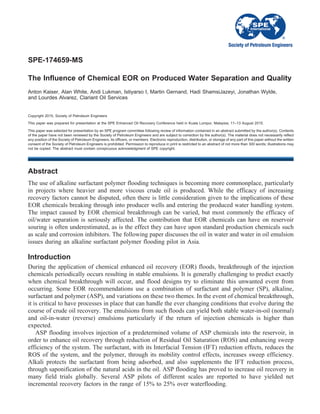
  • 15. Bottles 3 and 5 (from left) were EOR R-EB 7979 and EOR R-EB 13133 respectively, both at 600 ppm. EOR R-EB 13133 can be seen to have left a smaller emulsion layer. EOR R-EB 7958 (second from left) also showed good effect. Again, far right bottle was the Blank. Doses (from left) were 100, 200, 400, 600, 800 ppm. Far right was Blank. Very clean water started at 400 ppm. It was noticeable that increasing the dosage higher than this also led to an increase in the emulsion layer which was taken to be a sign of overtreatment. Figure 17—Further screening. ASP 700 ppm, Oil 1%. Figure 18—Ratio test of EOR R-EB 13133. ASP 700 ppm, Oil 1%. SPE-174659-MS 15
  • 16. Bottle no.2 (from left) was EOR R-EB 13133 at 800 ppm. Other candidates were unable to give effective treatment under these conditions although all were seen to have some effect when they were compared to the Blank (far right). The separated oil for EOR R-EB 13133 was seen to be black with only a thin layer of brown emulsion left on the top. The results seen from the deoiler testing were very promising; they indicate that specifically developed in-house EOR reverse emulsion breakers are able to mitigate the reverse emulsion that is expected to be produced by ASP pilot projects. The tests have shown that EOR R-EB 13133 is a very good candidate to treat the water that will be produced by the ASP pilot producer well. It is anticipated that using EOR R-EB 13133, in combination with EOR EB 13094, should mitigate the emulsion issues that are associated with the ASP EOR project on this oilfield in Asia. Conclusions An EOR fluid separation study was conducted for an ASP pilot in Asia. Various mixtures of produced water, polymer fluids and ASP fluids with crude oil emulsion from the EOR pilot producer well were mixed. The separation behavior of these crude oil mixtures was evaluated at different emulsion mixing intensities, different temperatures and emulsion breaker dosage rates. It is clear from the results that ASP fluids will have a significant influence on the separation behavior of the produced fluids and especially on the quality of the separated water. The currently in use emulsion breaker will not be able to handle the emulsion changes caused by the ASP breakthrough. The extent of the effect will depend on the concentration of ASP in the produced fluids as well as the ratio of oil to water and the amount of shear that the mixture is subjected to. The drastic changes of the oil to water and chemical ratios that occur during the formation of an oil bank in the reservoir will create challenging emulsion resolution issues during the treatment of the breakthrough fluids. It seems obvious that a 24/7 field support and subsequent continuous chemical optimization of the emulsion breakers would be required to ensure trouble-free oil production. The work done to evaluate the specifically developed in-house EOR emulsion breaker chemistries was performed on mixtures of ASP fluid and crude oil emulsion from the ASP pilot producer well. The main objective was fast water separation, low residual emulsion and clean separated water. In addition, the goal was to develop a chemistry that is able to treat the continuously changing emulsion during the chemical breakthrough. The test work showed that EOR EB 13094 seems to be able to ultimately resolve these water in oil emulsion issues. It is clear from the results that EOR EB 13094 can provide sufficient water Figure 19—Extreme conditions: 2000 ppm ASP, 10% oil. 16 SPE-174659-MS
  • 17. separation and low residual emulsion however it will not give sufficiently clean separated water on its own. In order to achieve good water quality it will be necessary to use a combination of water in oil emulsion breaker and oil in water emulsion clarifier / deoiler. The deoiler test work has demonstrated that the specifically developed in-house reverse EOR emulsion breaker chemistries are able to mitigate the reverse emulsions anticipated to be produced by the ASP pilot even at dynamically changing fluid ratios. EOR R-EB 13133 was seen to provide good separation when applied to a synthetic ASP emulsion, resulting in visibly clean and clear water. The use of both EOR EB 13094 and EOR R-EB 13133 should enable the production of both dry oil and clean water at this particular ASP pilot project when ASP containing fluids begin to appear from the producing well. Further product optimization needs to take place using “live” fluids straight from the well once the breakthrough occurs. 24/7 field support is highly recommended during breakthrough of the ASP fluids. Further work needs to be conducted to develop multifunctional water in oil / oil in water emulsion resolution product packages. References Aarra, M.G. and Skauge, A. (2000) Status of Foam Applications in North Sea Reservoirs. Paper 22 presented at the Annual International Energy Agency Workshop and Symposium, Edinburgh, UK, 19-22 September Aarra, M.G., Skauge, A., Sognesand, S., and Stenhaug, M. (1996) A foam Pilot Test Aimed at Reducing Gas Inflow in a Production Well at the Oseberg Field. Petroleum Geoscience, 2, 125 Blaker, T., Aarra, M.G., Skauge, A., Rasmussen, L., Celius, H.K., Martinsen, H.A., and Vassenden, F. (2002) Foam for Gas Mobility Control in the Snorre Field: The FAWAG Project. SPE 78824. SPE Reservoir Evaluation and Engineering 5(4), 317–323 Bonis, M. (2012) Managing the corrosion impact of dense phase CO2 injection for an EOR purpose. SPE 161207. Abu Dhabi International Petroleum Conference and Exhibition, Abu Dhabi, UAE, 11-14 November Hanssen, J.E., Holt, Torleif, Surguchev, L.M. (1994) Foam Processes: An Assessment of Their Potential in North Sea Reservoirs Based on a Critical Evaluation of Current Field Experience. SPE 27768. SPE/DOE Improved Oil Recovery Symposium, Tulsa, Oklahoma, 17-20 April Hoefner, M.L., Evans, E.M., Buckles, J.J., and Jones, T.A. (1995) CO2 Foam: Results from Four Developmental Field Trials. SPE 27787. Reservoir Engineering, 10(4), 273–281 Iwere, F.O., Heim, R.N., and Cherian, B.V. (2012) Numerical Simulation of Enhanced Oil Recovery in the Middle Bakken and Upper Three Forks Tight Oil Reservoirs of the Williston Basin. SPE 154937. SPE Americas Unconventional Resources Conference, Pittsburgh, Pennsylvania, USA 5-7 June Khan, R., Lee, J., Sams, G. (2009) Produced Water Viscosity Effects on IGF Sweeping Efficiency. Annual Produced Water Society Seminar, 21-23 January, Houston, TX, USA Koottungal, L. (2012) Worldwide EOR Survey. Oil and Gas Journal, 2 April Krause, R.E., Lane, R.H., Kuehne, D.L., and Bain, G.F. (1992) Foam Treatment of Producing Wells to Increase Oil Production at Prudhoe Bay. SPE 24191. SPE/DOE Enhanced Oil Recovery Symposium, Tulsa, Oklahoma, 22-24 April Krumrine, P.H. Mayer, E.H., and Brock, G.F. (1985) Scale Formation During Alkaline Flooding. SPE 12671. Journal of Petroleum Technology, 37(8), 1466–1474 Penney, R., Moosa, R., Shahin, G., Hadhrami, F., Kok, A., Engen, G., van Ravesteijn, O., Rawnsley, K., and Kharusi, B. (2005) Steam Injection in Fractured Carbonate Reservoirs: Starting a New Trend in EOR. IPTC 10727. International Petroleum Technology Conference, Doha, Qatar, 21-23 November SPE-174659-MS 17
  • 18. Sahin, S., Kalfa, U., and Celebioglu, D. (2012) Unique CO2-Injection Experience in the Bati Raman Field May Lead to a Proposal of EOR/Sequestration CO2 Network in the Middle East. SPE 139616. SPE Economics & & Management, 4(1), 42–50 Srivastava, M., Zhang, J., Nguyen, Q.P., and Pope, G.A. (2009) A Systematic Study of Alkali Surfactant Gas Injection as an Enhanced Oil Recovery Technique. SPE 124752. SPE Annual Technical Conference and Exhibition, New Orleans, Louisiana, 4-7 October Svorstøl, I., Blaker, T., Tham, M.J., and Hjellen, A. (1997) A Production Well Foam Pilot in the North Sea Snorre Field-Application of Foam to Control Premature Gas Breakthrough. Presented at the 9th European Symposium on Improved Oil Recovery, The Hague, 20-22 October Wang, Z., Zhao, L., Li, F., He, J., and Chen, L. (1999) Characteristics Study of Hydrocyclone Used for Separating Polymer-Flood Produced-Water. International Offshore and Polar Engineering Conference, Brest, France, May 30-June 4 Wylde, J.J., Allan, K., McMahon, J., and Mayner, S. (2011) Scale Inhibitor Application in Northern Alberta - A Case History of an Ultra High Temperature Scale Inhibitor Solution in Fire Tube Heater Treaters. SPE 141100. Presented at the International Symposium on Oilfield Chemistry, The Woodlands, TX, USA, 11-13 April Wylde, J. J., Slayer, J. L. and Barbu, V. (2013) Polymeric and Alkali-Surfactant Polymer Enhanced Oil Recovery Chemical Treatment: Chemistry and Strategies Required After Breakthrough into the Process SPE 164078 Yee, H.V., Kechut, N.I., and Razak, W.N.A.W (2007) Enhanced Oil Recovery Potential of Heavy-Oil Fields in Africa. SPE 108513. International Oil Conference and Exhibition, Veracruz, Mexico, 27-30 June Yongbin, W., Desheng, M., Shangqi, L., Hongzhuang, W., and Xin, Z. (2010) EOR of Superheated Steam Injection in Shallow Heavy Oil Reservoir: A Case Study. SPE 131224. International Oil and Gas Conference and Exhibition in China, Beijing, China, 8-10 June You, Q., Zhao, F., Wang, Y., and Mu, L. (2007) Comparison of the properties of injected and released polyacrylamide in polymer flooding. Journal of Beijing University of Chemical Technology (Natural Science Edition) 34(4): 414–417 Zhang, Y.P., Huang, S., and Dong, M. (2005) Determining the Most Profitable ASP Flood Strategy for Enhanced Oil Recovery. Journal of Canadian Petroleum Technology, 44(2) Zheng, F., Quiroga, P., and Sams, G.W. (2011) Challenges in Processing Produced Emulsion from Chemical Enhanced Oil Recovery - Polymer Flood Using Polyacrylamide. SPE 144322. Presented at the SPE Enhanced Oil Recovery Conference, Kuala Lumpur, Malaysia, 19-21 July 18 SPE-174659-MS