- The document summarizes the internship report of Adnan Hatim Nek at the Pakistan Petroleum Limited (PPL) Sui Gas Field.
- It describes the various departments and processes at the Sui Field Gas Compression Station including QHSE, administration, planning, operations, machinery, and compression.
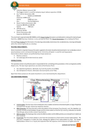
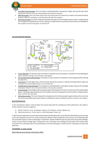
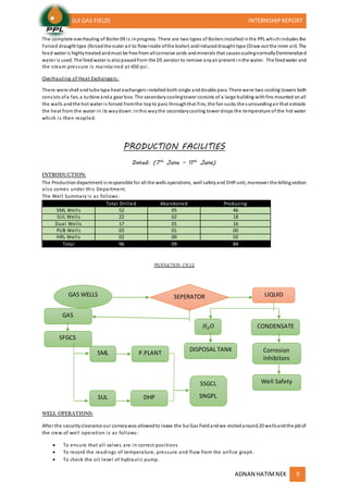
- Key parts of the compression process are described involving slug catchers, scrubbers, knockout drums, low pressure and high pressure compression and cooling.


![SNGPL [D]](https://cdn.slidesharecdn.com/ss_thumbnails/sngpld-131005144232-phpapp01-thumbnail.jpg?width=640&height=640&fit=bounds)