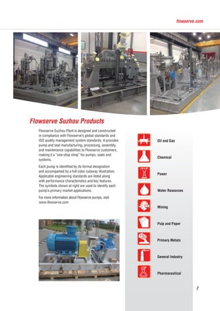
Flowserve Suzhou Plant manufactures pumps and seals. It was established in 2006 as Flowserve's first wholly owned facility in China. The plant was expanded with a new facility covering 44,500 square meters that was opened in 2013. The Suzhou plant provides pump and seal manufacturing, processing, assembly, and maintenance capabilities. It serves as a "one-stop shop" for pumps, seals, and systems for customers in industries such as oil & gas, power, chemical, and water.
![2
Flowserve [NYSE: FLS] is the world’s premier provider
of industrial flow management services. The company
produces engineered pumps, industrial valves, control
valves, actuators and precision mechanical seals, and
provides a range of related flow management services,
primarily for the process industries. Flowserve has more
than20,000employeesandoperatesinover55countries.
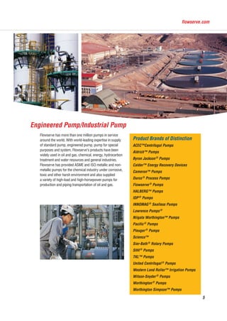
More than one million pumps manufactured by
Flowserve are serving in various industries around
the world. Flowserve is the world’s leading pump
manufacturer in petroleum, chemical processing and
power generation industries. The valve, steam strap,
automatic control product and fluid management
service series of Flowserve have been widely used in
chemical, petrochemical, power generation, oil and gas,
food and other industries. Our seal and seal system
have been used in many kinds of rotary machines for
preventing from fluid leakage.
Overview
Flowserve has been maintaining its consistent
development strategy in China, and continues
to expand regional coverage to deliver better
service to local customers. Since the beginning
in early 1990s, Flowserve has successfully
met the most challenging requirements of our
customers throughout China’s oil and gas,
chemical, petrochemical, power generation
and fossil power industries. Opened in July
2006, the Suzhou plant represents Flowserve’s
first wholly owned facility to serve the China
market. Afterwards, Flowserve also opened
Quick Response Centers (QRCs) in Shanghai,
Suzhou and Dalian. Flowserve has sales offices
in Beijing, Shanghai and Shenzhen, in addition
to joint venture (JV) businesses in Suzhou
and Changsha. In 2013, Flowserve has put
its Suzhou new plant into formal operation
to provide international quality products and
services to local customers.
Pump and Seal Business Network
Shenzhen
Shanghai
Shuzhou
Dalian
Beijing
Manufacturing Plants
Quick Response Centers
Sales Offices
福斯中国EN-20151104.indd 2 2015/12/7 10:54:27](https://image.slidesharecdn.com/815e1b48-d043-4fbe-91d4-ffe5dbf661d5-160816004321/85/Flowserve-suzhou-2-320.jpg)