Downloaded 118 times


![REFERANCE
[1]. Designed in CATIA V5.
[2]. https://goo.gl/images/Jk1sMz
[3]. https://goo.gl/images/HBofA3
[4]. https://goo.gl/images/jQUPSp
[5]. https://goo.gl/images/EIqChq
[6]. https://goo.gl/images/4adldf
[7]. https://goo.gl/images/hf1xTC
[8]. https://goo.gl/images/UDiw2S
[9]. Designed in CATIA V5.](https://image.slidesharecdn.com/pptbyaftab-180415193942/75/TRAIN-WHEEL-POWER-GENERATION-20-2048.jpg)


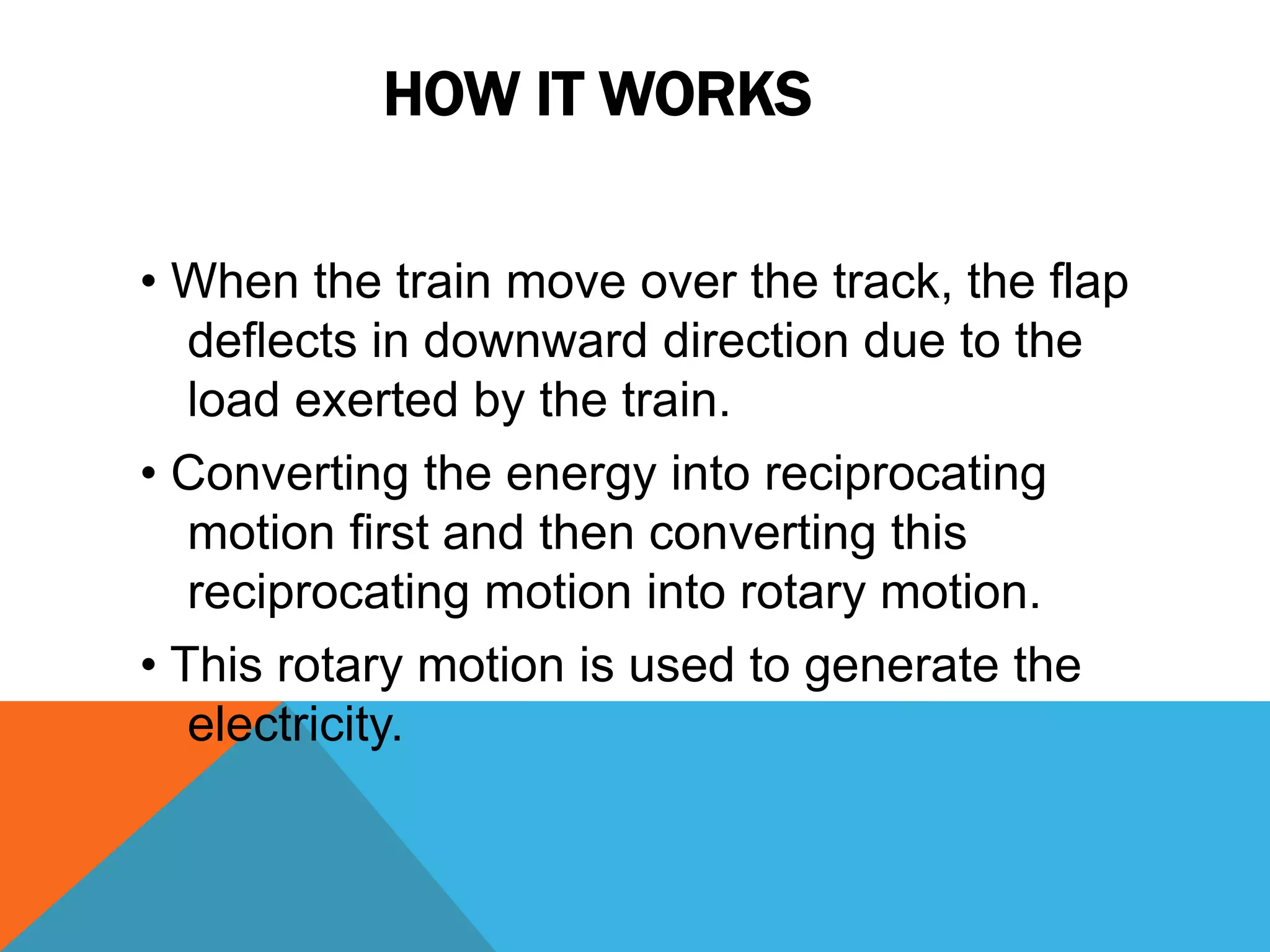
This document presents a project to generate electricity from train wheels on railway tracks. The system uses a rack and pinion assembly, chain drive, flywheel, and DC generator. As a train passes over the track, the wheel deflects a flap which converts the motion to rotational energy through the drive components. This rotation powers the generator to produce electricity which can be stored in a battery and used to power railway equipment. The system provides a solution for energy crises by tapping energy from passing trains without additional fuel. It is a non-conventional and eco-friendly way to generate power.