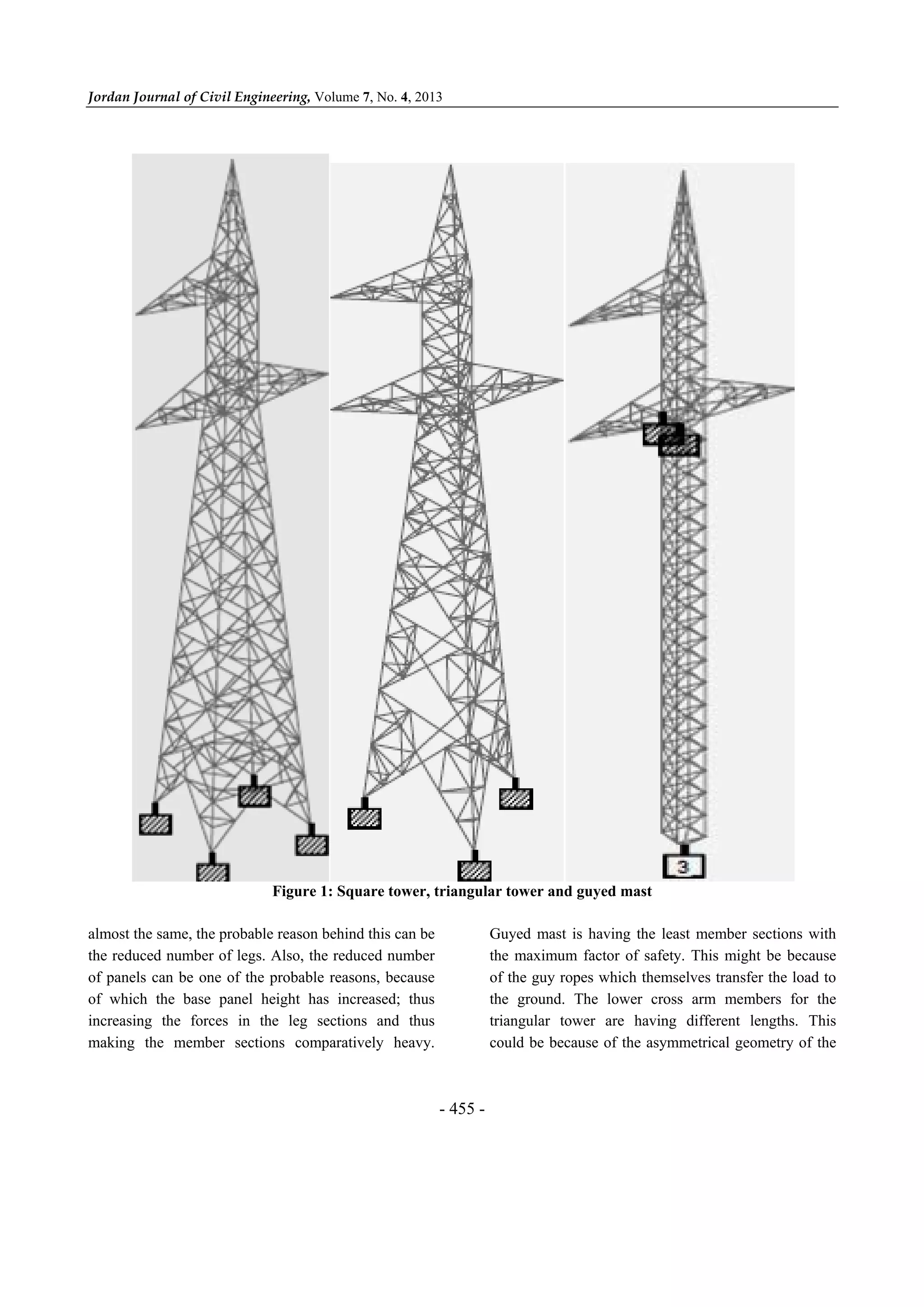
The document analyzes and compares three different configurations of 220kV transmission line towers: a square base self-supporting tower, a triangular base self-supporting tower, and a square base guyed mast tower. Each tower is modeled and analyzed using STAAD software. The triangular tower has the heaviest member sections for the legs to handle the same loads with fewer legs. The guyed mast tower has the lowest forces in the leg members due to load transfer through guy ropes. The triangular tower experiences the highest forces in the leg members. Overall, the triangular tower requires the heaviest member sections to support the same loads as the other tower configurations.
International Journal of Engineering Research and Applications (IJERA) is an open access online peer reviewed international journal that publishes research and review articles in the fields of Computer Science, Neural Networks, Electrical Engineering, Software Engineering, Information Technology, Mechanical Engineering, Chemical Engineering, Plastic Engineering, Food Technology, Textile Engineering, Nano Technology & science, Power Electronics, Electronics & Communication Engineering, Computational mathematics, Image processing, Civil Engineering, Structural Engineering, Environmental Engineering, VLSI Testing & Low Power VLSI Design etc.
Cost Optimization of a Tubular Steel Truss Using Limit State Method of DesignIJERA Editor
Limit state method helps to design structures based on both safety and serviceability. The structures are designed to withstand ultimate loads or the loads at which failure occurs unlike working stress method where only service loads are considered. This leads to enhanced safety. Also unlike the working stress method, the structures are economical. It is also better than ultimate load method as serviceability requirement is also taken care of by considering various safety factors for all the load types and structures do not undergo massive deflection and cracks. For tubular sections, higher strength to weight ratio could result in upto 30% savings in steel .Due to the high torsional rigidity and compressive strength, Tubular sections behave more efficiently than conventional steel section This study is regarding the economy, load carrying capacity of all structural members and their corresponding safety measures.
This presentation aims to design and analysis of the structure of Hyperloop chassis, which was designed for Hyperloop Pod Building Competition organized by SpaceX 2019.
An investigation of effects of axle load and train speed at rail joint using ...eSAT Publishing House
IJRET : International Journal of Research in Engineering and Technology is an international peer reviewed, online journal published by eSAT Publishing House for the enhancement of research in various disciplines of Engineering and Technology. The aim and scope of the journal is to provide an academic medium and an important reference for the advancement and dissemination of research results that support high-level learning, teaching and research in the fields of Engineering and Technology. We bring together Scientists, Academician, Field Engineers, Scholars and Students of related fields of Engineering and Technology.
International Journal of Engineering Research and Applications (IJERA) is an open access online peer reviewed international journal that publishes research and review articles in the fields of Computer Science, Neural Networks, Electrical Engineering, Software Engineering, Information Technology, Mechanical Engineering, Chemical Engineering, Plastic Engineering, Food Technology, Textile Engineering, Nano Technology & science, Power Electronics, Electronics & Communication Engineering, Computational mathematics, Image processing, Civil Engineering, Structural Engineering, Environmental Engineering, VLSI Testing & Low Power VLSI Design etc.
In the present era the technology in communications has developed to a very large extent. The communication industries have seen a tremendous increase in last few years which have resulted in installation of large number of towers to increase the coverage area and network consistency. In wireless communication network these towers play a significant role hence failure of such structure in a disaster is a major concern. Therefore utmost importance should be given in considering all possible extreme conditions for designing these towers. In most of the studies, the researches have considered the effect of wind only on the four legged self-supporting towers. In this dissertation, a four legged lattice tower is analyzed and designed along with foundation details.
SAIF ALDIN ALI MADIN
سيف الدين علي ماضي
S96aif@gmail.com
Buckling test
MECHANICS OF MATERIALS
A fundamental condition in all problems is the equilibrium of
internal and external forces. If the system of forces is
disturbed owing to a small displacement of a body, two
principal situations are possible: either the body will return
to its original configuration owing to restoring forces during
displacement, or the body will accelerate farther away from
its original state owing to displacing forces. The latter
situation is termed instable equilibrium.
The instability of structural members subjected to
compressive loading (see Fig. 1(b)) may be regarded as a
mode of failure, even though stress may remain elastic, owing to excessive
deformation and distortion of the structure. This mode of failure is termed
buckling and is prevalent in members for which the transverse dimension is
small compared with the overall length
Static Stress Analysis of Connecting Rod Using Finite Element ApproachIOSR Journals
Every vehicle which equipped with internal combustion engine requires connecting rod. In this paper a static stress analysis of connecting rod made up of SS 304 used in Cummins NTA 885 BC engine is conducted, using finite element method. After measuring the dimension of connecting rod, model is developed in CATIA V5 software and imported to ANSYS WORKBENCH 14.0 software. Static analysis is done by fixing the smaller end and load is applied at bigger end of connecting rod. Stress developed at four different sections is used for analysis. Maximum stress point and section prone to failure is finding out by this analysis. Graph between stress and load is plotted at section prone to failure and result of stress analysis is shown with the help of image.
It is an Powerpoint on Hydraulic Scissor Lift used for material handling in industries. PPT consist of design procedure, design consideration and calculation of lift.
Stress analysis on steering knuckle of the automobile steering systemeSAT Journals
Abstract Steering Knuckle plays major role in many direction control of the vehicle it is also linked with other linkages and supports the vertical weight of the car. Therefore, it requires high precision, quality, and durability. The main objective of this work is to explore performance opportunities, in the design and production of a steering knuckle. This can be achieved by performing a detailed load analysis. Therefore, this study has been dealt with two steps. First part of the study involves modeling of the steering knuckle with the design parameters using the latest modeling software, and also it includes the determination of loads acting on the steering knuckle as a function of time. This is done for finding out the minimum stress area. Then the stress analysis was performed using analysis software. The steering knuckle can be modeled, and analyzed under the actual load conditions. This may also improve the depth knowledge of its function and performance in terms of durability and quality. Keywords: Steering knuckle, stress analysis and Finite Element Analysis (FEA).
IJERA (International journal of Engineering Research and Applications) is International online, ... peer reviewed journal. For more detail or submit your article, please visit www.ijera.com
Load centers get generated electricity from power
stations that are usually far; uninterrupted consumption or usage
of power has increased in last few years. Transmission system is
the system by means of which electricity is transferred from place
of generation to the consumers. Overhead wires or conductors
are the medium used for transmission of power. These wires are
visible to wind, heat and ice. The efficiency of the power system
increases if the losses of these overhead wires are minimal. These
losses are based on the resistive, magnetic and capacitive nature
of the conductor. It is necessary to create or make proper design
of these conductors accompanied by proper installation. To
balance the working and strength of overhead transmission line
and to minimize its capacitive effect the conductors must be
installed in catenary shape. The sag is required in transmission
line for conductor suspension. The conductors are appended
between two overhead towers with ideal estimation of sag. It is
because of keeping conductor safety from inordinate tension. To
permit safe tension in the conductor, conductors are not
completely extended; rather they are allowed to have sag. For
same level supports this paper provides sag and tension
estimation with different wind speeds under low operating
temperature 2 °C. To calculate sag-tension estimation of ACSR
(Aluminum Conductor Steel Reinforced) overhead lines three
different cases are provided with normal and high wind speed
effects. Four different span lengths are taken for equal level
supports. ETAP (Electrical Transient and Analysis Program) is
used for simulation setup. The results shows that wind speed has
great impact upon line tension and with addition of wind speed
the sag of line remains unaltered while tension changes.
Moreover tension gets increase while increase in wind speed.
UNIT - 06 TRANSMISSION LINES AND SUBSTATIONSPremanandDesai
Code of practice for Transmission lines and substations, transmission line materials and their specifications, types of Towers, ACSR conductors and Number of Disc insulators in suspension string, strain string, span and height of towers for 66 KV, 110 KV, 220 KV transmission lines, concept of single circuit and double circuit transmission lines, method of calculating the Quantity of transmission line materials, Prepare the schedule of materials
(only) for 66 KV,110 KV and 220 KV single circuit transmission lines. 66KV/11KV, 5 MVA Substations- Single Line diagram, list of Electrical equipment's/ materials (only) and their
specifications.
Concept of energy transmission & distribution ZunAib Ali
Downlaod is NOW Allowed (08/06/2016)
for more help: email me at zunaib_91@yahoo.com
Purpose of Electrical Transmission System
Main Parts of Power System
One-Line Diagram of Generating Station
Main Parts of Generating Station
Components of a Transmission Line
FE Analysis of Bolted Connections for Wind Turbine Towers by Yadneshwar S. JoshiYadneshwar Joshi
Analysis of bolted flange plate and friction connections, to assess the potential benefits from implementing them in wind towers.
To investigate the performance of a new friction connection and to compare it with conventional ring-flange connections
Comparative study for strength, ease of erection, man power and material consumption/cost
DESIGN AND OPTIMIZATION OF ELECTROSTATIC PRECIPITATOR USING FINITE ELEMENT AN...IAEME Publication
An electrostatic precipitator is designed to trap and remove dust particles from the exhaust gas. The computer aided design and finite element analysis of electrostatic precipitator cone structure has been carried out. For static structure analysis two models (Model A and Model B) is being
considered having horizontal and vertical stiffener arrangement.
2. Jordan Journal of Civil Engineering, Volume 7, No. 4, 2013
- 451 -
Transmission Line Components
The following parameters for transmission line and
its components are assumed from I.S. 802: Part 1: Sec:
1:1995, I.S. 5613: Part 2: Sec: 1:1989.
Transmission Line Voltage: 220 kV (A. / C.)
Right of Way (recommended): 35, 000 mm
Angle of Line Deviation: 0 to 2 degrees
Terrain Type Considered: Plain
Terrain Category: 2 (Normal cross country lines
with very few obstacles)
Return Period: 50 yrs
Wind Zone: 4
Basic Wind Speed: 47 m/s
Basic Wind Pressure: 71.45 kg/sqm
Tower Type: Self-Supporting Tower, Suspension
Type Tower, Tower Type “A”
Tower Geometry: Square Base Tower
No. of Circuits: Single Circuit
Tower Configuration: Vertical Conductor
Configuration
Tower Shape: Barrel Shaped
Bracing Pattern: Warren Type (Double Web
System), Portal System (K Type)
Cross Arm: Pointed
Body Extension: Not Considered
Steel Used: Mild Steel (IS-2062)
Slope of Tower Leg: 40 to 90 (Permissible)
Conductor Material: ACSR, (Aluminium
Conductor Steel Reinforced)
Conductor Configuration: Zebra
Maximum Temperature: 75°C (ACSR)
Number of Ground Wires: Single
Peak Type: Triangular
G.W. Type: Earth wire – 7 / 3.66
Shielding Angle: 300
Maximum Temperature: 53°C (7 / 3.66)
Insulator Type: I String
Number of Insulator Discs: 14
Size of Insulator Disc: 255 * 145 mm (Skirt
Diameter)
Length of Insulator String: 2,340 mm
Minimum Ground Clearance: 7,000 mm
Sag Error Considered: 160 mm
Creep Effect: Not Considered
Mid Span Clearance: 8,500 mm
Minimum Height above G.L.: 28,555 mm
Width at Hamper Level: 1,500 mm (Square Tower)
Width at Base: 4,500 mm (Square Tower)
Phase to Phase Clearance: Vertical Spacing
between Conductors (Minimum): 5,200 mm.
Horizontal Spacing between Conductors
(Minimum): 8,500 mm
Lightning Impulse Level (Air Clearance): 1700 mm
Minimum Phase to Earth (Air Clearance): 1970 mm
Phase to Ground Metal Clearance:
-Swing Angle:
0° - 2130 mm
15° - 1980 mm
30° - 1830 mm
45° - 1675 mm
Tower Weight (Minimum): 2,570 kg
Base Width (C.L.) / Height above G.L. = 1: 6.3
Minimum Thickness of Member:
- Leg Member, G.W. Peak and Lower Member of
C.A.: 5 mm
- Others: 4 mm
Permissible Weight Span:
• Normal Condition:
Maximum: 525 mm
Minimum: 200 mm
• Broken Wire Condition:
Maximum: 315 mm
Minimum: 100 mm
Normal Span: 320 mm to 380 mm
Design Span: 350 mm
Wind Span = Normal Span: 350 mm
Weight Span: 1.5 X 350 mm
Concrete Level to Ground Level: 225 mm
Sag Tension for Conductor and Ground Wire
Indian standard codes of practice for use of
structural steel in over-head transmission line towers
have prescribed following conditions for the sag
3. Analysis of Transmission… C. Preeti and K. Jagan Mohan
- 452 -
tension calculations for the conductor and the ground
wire:
Maximum temperature (75°C for ASCR and 53°C
for ground wire) with design wind pressure (0%
and 36%).
Every day temperature (32°C) and design wind
pressure (100%, 75% and 0%).
Minimum temperature (0°C) with design wind
pressure (0% and 36%).
IS 802: part 1:sec 1: 1995 states that conductor/
ground wire tension at every day temperature and
without external load should not exceed 25 % (up to
220 kV) for conductors and 20% for ground wires of
their ultimate tensile strength. Sag tensions are
calculated by using the parabolic equations as
discussed in the I.S. 5613: Part 2: Sec: 1: 1989 for both
the conductor and ground wire. We have considered
the sag of ground wire as 90% the sag of the conductor
at 0°C and 100% wind condition.
Parabolic Equation
F . F K α. t. E
L . ∂ . q . E
24
Take K F1
L . ∂ . q . E
24. F
Table 1. Sag tension for conductor (ASCR)
Temperature variation C 0 32 75
Wind variation % 0 0. 36 0 0.75 1.0 0
Tension= F x A (kg) 4060 4879 3322 5763 6804 2687
Sag (m)
6.114 5.088 7.471 4.307 3.648 9.239
Table 2. Sag tension for ground wire
Temperature variation C 0 32 53
Wind variation % 0 0. 36 0 0.75 1.0 0
Tension= F x A (kg) 1520 2001 1327 2629 3127 1226
Sag (m) 5.874 4.462 6.725 3.395 2.855 7.284
Configuration of Towers
Configurations of all three towers are done by first
fixing the outline of all the towers as per the Indian
standard requirements.
The base width of triangular tower is restricted as
(4/3) X base width of square tower and guyed mast
as simply 1000 mm.
The width at the hamper level for both the square
tower and the triangular tower is reduced to (1/3) of
the base width, but the width of the guyed mast is
kept constant throughout the height of the tower.
The members for all the towers are so chosen that
the effective length is kept between 1200 mm and
1500 mm.
The bracing angle for all the towers is kept between
400 and 500.
The minimum factor of safety is kept as 1.1 for the
design of angle members.
The square and triangular towers are having their
legs inclined till hamper level (for tower body), while
guyed mast is having straight legs. All the towers are
having straight legs above the hamper level (cage).
Final height of each of the towers is taken as the
maximum of both conditions; that is 29900 mm. Thus,
all the towers are having the same height. Horizontal
grounded metal clearance for all the towers is the same,
4. Jordan Journal of Civil Engineering, Volume 7, No. 4, 2013
- 453 -
except for the minor change in the slope of tower leg.
Horizontal clearance between the phases is maximum
for the triangular tower and the least for guyed mast.
This is because of their width at the hamper level.
Table 3. Configuration of tower
Square tower Triangular tower Guyed mast
Base width 4500 mm 6000 mm 1000 mm
Hamper width (L.C.A.) 1500 mm 2000 mm 1000 mm
Hamper width (U.C.A.) 1500 mm 2000 mm 1000 mm
Height till L.C. A. Level 18900 mm 18900 mm 18900 mm
Height till U.C. A. Level 24100 mm 24100 mm 24100 mm
Total Tower Height (from G.L.)
Minimum 28555 mm 28555 mm 28555 mm
Peak clearance 29100 mm 29600 mm 28700 mm
Mid-span clearance 29900 mm 29900 mm 29900 mm
Horizontal Gr. Metal Clear. 3600 mm 3600 mm 3600 mm
Horizontal Spacing between Cross Arm Tip
Minimum 8500 mm 8500 mm 8500 mm
Actual 8700 mm 9200 mm 8200 mm
Wind Loads on Towers
Wind loads on all the towers are calculated
separately by developing excel programs by following
Indian Standards. For finding the drag coefficients for
the members of triangular tower, the solidity ratio is
derived from Table 30 –IS-875 (part 3)-1987 in the
similar fashion as prescribed in the IS- 826 (part-1/sec
1)-1995.
Design Wind Pressure
To calculate design wind pressure on conductor,
ground wire, insulator and panels:
.
where,
Pd = design wind pressure in N/m2
Vd = design wind speed in m/s
To calculate design wind pressure
VR = 10min wind speed (or) reduced wind speed
VR = Vb/k0
Vb = basic wind speed
K0 =1.375 [conversion factor]
K1 = risk coefficient
K2 = terrain roughness coefficient.
Wind Loads on Conductor/Ground Wire
To calculate wind loads on conductor and ground
wire
Fwc = wind load on conductor
Pd = design wind pressure
Cdc = drag coefficient for ground wire=1.2
drag coefficient for conductor = 1.0
L = wind span
d = diameter of conductor/ground wire
Gc = gust response.
Wind Load on Insulator
To calculate wind load on insulator
5. Analysis of Transmission… C. Preeti and K. Jagan Mohan
- 454 -
where,
AI = 50% area of insulator projected parallel to the
longitudinal axis of string
GI = gust response factor for insulator
Cdi = drag coefficient, to be taken as 1.2.
Wind Load on Panels
To calculate wind load on panels
Cdt = drag coefficient for panel considered against
which the wind is blowing
Ae = effective area of the panel
GT = gust response factor for towers.
Table 4. Wind loading on towers
Height (m) / Wind (kg) (from G.L.) Square Tower Triangular Tower Guyed Mast
0 292 306 129
8.91 - - 279
10.5 475 - -
12.14 - 461 -
18.9 243 210 195
20.2 118 111 101
24.1 127 119 108
25.4 107 101 89
29.1 122 118 103
Total 5571 5353 3708
No. of exposed members 180 195 174
The square tower is facing the maximum total wind
load followed by the triangular tower and then the
guyed mast. This implies that the member sectional
area exposed to wind is maximum in the square tower.
The maximum number of tower members exposed to
the wind is in the triangular tower followed by the
square tower and then the guyed mast. This might be
because of the fact that the loading is the same (other
than wind), thus the triangular tower is handling same
forces (almost) by three legs so the member sections
have increased. The lowest panel of triangular tower is
having the highest wind load followed by the square
tower and then the guyed mast. This might be because
of the fact that the panel height of the triangular tower
is comparatively higher as the number of panels is
reduced in the trunk of the tower.
Analysis of Towers
All the three towers are modelled and analyzed in
STAAD Pro2004.
Following results were obtained.
Square tower is found to have the maximum node
deflection throughout the tower height, followed by the
triangular tower and then the guyed mast. Guyed mast
is having the least deflection at the lower cross arm
level as those are the connection points of the guy
ropes. Triangular tower is having the maximum forces
in the legs members. The probable reason behind this
can be the reduced number of legs. Guyed mast is
having the least forces for the leg members. This is
because of the guy ropes which themselves transfer the
load to the ground. Guyed mast is having the maximum
forces for the lower cross arm members.
Design of Towers
The tower is designed and summed as:
Triangular tower is having the heaviest member
section for the legs. As the forces (other than wind) are
6. Jordan Journ
almost the sa
the reduced n
of panels can
of which th
increasing th
making the
nal of Civil Eng
ame, the proba
number of leg
n be one of th
he base panel
he forces in
member sec
ngineering, Vol
Figure 1:
able reason be
gs. Also, the r
he probable r
l height has
the leg sec
ctions compa
lume 7, No. 4, 2
Square towe
ehind this can
reduced numb
reasons, becau
increased; th
ctions and th
aratively heav
2013
- 455 -
er, triangular
be
ber
use
hus
hus
vy.
G
th
of
th
tri
co
r tower and g
uyed mast is
he maximum f
f the guy rope
he ground. Th
iangular towe
ould be becau
uyed mast
having the le
factor of safe
es which them
he lower cro
er are havin
use of the asym
east member
ety. This migh
mselves transf
oss arm mem
ng different l
mmetrical geo
sections with
ht be because
fer the load to
mbers for the
lengths. This
ometry of the
h
e
o
e
s
e
7. Analysis of Transmission… C. Preeti and K. Jagan Mohan
- 456 -
tower. Square tower is having the maximum factor of
safety for the upper cross arm members. This behavior
might be because of the minimum length of the
members. Upper cross arm member sections are found
to be the same for all the towers. This may be because
these members are designed as the tension members
and steel already has good margin of safety in tension.
Table 5. Maximum force in the leg member
Guyed Mast Triangular Tower Square Tower
Panel no. Compressive
kg
Tensile
kg
Compressive
kg
Tensile
kg
Compressive
kg
Tensile
kg
0 3981 1160 - - - -
1 2492 977 31175 28247 22945 20716
2 2662 1292 28469 25907 22033 20028
3 2839 1610 24726 22324 20560 18698
4 3013 1927 21430 19256 18306 16723
5 3188 2244 18355 16182 16536 15028
6 3362 2560 13826 11874 14242 12936
7 3535 2876 - - 12892 11542
8 3708 3191 - - 10604 9490
9 3884 3503 - - - -
10 4608 3308 - - - -
11 5334 3055 - - - -
12 6063 2799 - - - -
13 6792 2674 - - - -
14 7522 3924 - - - -
15 8255 4172 - - - -
16 8990 4916 - - - -
17 9736 5655 - - - -
18 10463 6381 - - - -
19 11302 7148 - - - -
20 8498 12350 9999 8343 7950 5454
21 9013 1178 - - - -
22 7853 8864 7455 6799 6755 6231
23 6556 7116 6206 4982 5509 4979
24 6638 5412 6835 4606 5090 3348
25 4008 3359 4660 2684 3322 2628
26 5256 4955 4610 3537 3553 3459
Table 6. Maximum force in cross arm
Guyed Mast Triangular Tower Square Tower
Panel no. Compressive kg Tensile kg Compressive kg Tensile kg Compressive kg Tensile kg
Lower member
Lower 6268 4307 4969 3645 4651 2912
Upper 6767 4478 5463 2312 5111 2675
Upper member
Lower 1320 4801 1037 5418 669 4410
Upper 631 4064 825 5729 276 4150
8. Jordan Journal of Civil Engineering, Volume 7, No. 4, 2013
- 457 -
Table 7. Maximum force in cross arm
Height (m) Square Tower (mm) Triangular Tower (mm) Guyed Mast (mm)
0 0 0 0
18.9 85 71 8
20.2 98 90 14.5
24.1 142 129 60
25.4 157 142 76
29.9 216 192 144
Table 8. Design of leg members
Guyed mast Triangular tower Square tower
Panel
no.
Angle section
Effective
length (cm)
FOS Angle section
Effective
length (cm)
FOS Angle section
Effective length
(cm)
FOS
0 65X65X05 87 3.4 100X100X8 129 1.1 90X90X8 110 1.3
1 65X65X05 99 5.1 100X100X8 127 1.2 90X90X8 155 1.2
2 65X65X05 99 5.1 90X90X8 107 1.3 90X90X8 140 1.4
3 65X65X05 99 4.5 90X90X8 130 1.4 90X90X6 125 1.2
4 65X65X05 99 4.3 90X90X6 110 1.3 90X90X6 135 1.3
5 65X65X05 99 4.1 75X75X6 105 1.3 75X75X06 110 1.3
6 65X65X05 99 3.8 - - - 75X75X06 95 1.5
7 65X65X05 99 3.6 - - - 75X75X06 160 1.3
8 65X65X05 99 3.5 - - - - - -
9 65X65X05 99 3.3 - - - - - -
10 65X65X05 99 2.8 - - - - - -
11 65X65X05 99 2.4 - - - - - -
12 65X65X05 99 2.1 - - - - - -
13 65X65X05 99 1.9 - - - - - -
14 65X65X05 99 1.7 - - - - - -
15 65X65X05 99 1.6 - - - - - -
16 65X65X05 99 1.4 - - - - - -
17 65X65X05 99 1.3 - - - - - -
18 65X65X05 99 6.3 - - - - - -
19 65X65X05 99 1.1 - - - - - -
20 65X65X05 130 1.3 75X75X06 130 1.7 65X65X05 130 1.3
21 65X65X05 97 1.4 - - - - - -
22 65X65X05 98 1.6 65X65X05 130 1.4 65X65X05 137 1.6
23 65X65X05 98 2.0 65X65X05 130 1.7 65X65X05 127 2.0
24 65X65X05 98 2.0 65X65X05 130 1.5 65X65X05 127 2.1
25 65X65X05 131 2.6 65X65X05 133 2.2 65X65X05 132 3.2
26 65X65X05 151 1.7 65X65X05 153 1.9 65X65X05 152 2.5
RESULTS AND DISCUSSION
As all the towers are designed with enough factor
of safety, the self weight of different towers obtained is
as follows:
Square Tower 2775 kg
Triangular Tower 2519 kg
Guyed Mast 1666 kg.
Triangular tower is compared with the square tower
in the following aspects:
1. The self weight for the triangular tower is found to
be 9.23% less than that of the square tower. Hence,
the triangular tower is more economical than the
square tower (self-supporting tower).
9. Analysis of Transmission… C. Preeti and K. Jagan Mohan
- 458 -
Table 9. Design of cross arms
Guyed mast Triangular tower Square tower
Panel no. Angle section
Effective
length (cm)
FOS Angle section
Effective
length (cm)
FOS
Angle
section
Effective
length (cm)
FOS
Lower members
Lower 75X75X6 136 2.4 75X75X6 164 2.6 75X75X6 123 3.4
65X65X5 120 4.7
Upper 75X75X6 136 2.2 75X75X6 164 2.4 75X75X6 123 3.1
65X65X5 124 4.3
Upper members
Lower 50X50X4 143 1.4 50X50X4 143 1.2 50X50X4 130 1.5
Upper 50X50X4 154 1.4 50X50X4 128 1.2 50X50X4 146 1.6
2. The triangular tower is found to have the lesser
amount of node deflection throughout the height of
the tower as compared with the square tower. This
implies that the triangular tower is behaving more
rigidly than the square tower.
3. The square tower is facing the maximum total
wind load followed by the triangular tower and
then the guyed mast. This implies that the member
sectional area exposed to wind is maximum in the
square tower.
4. The lowest panel of triangular tower is having the
highest wind load followed by the square tower
and then the guyed mast. This might be because of
the fact that the panel height of the triangular tower
is comparatively higher as the number of panels is
reduced in the trunk of the tower.
5. The triangular tower is found to have little higher
amount of axial forces in the leg members in
comparison with the square tower. This might be
because the forces are being transferred by three
legs instead of four.
Guyed mast is coming all the way more economical
than the triangular tower and the square tower. Even
the self weight of the tower, wind loading on the tower,
axial forces in the members (except the lower cross
arm members) and the node deflection all are coming
comparatively lesser. The above noted weight of guyed
mast is excluding the self weight of guy ropes. The
different structural behavior of the guyed mast and its
requirements need to be checked before its use. The
value of land is one of the major factors to be taken
into consideration in case of guyed mast. The saving in
the cost of transmission line by using guyed mast can
be nullified by the premium value of land.
CONCLUSIONS
Least weight of the tower implies greatest economy
in the transmission line cost. Following conclusions
can be made:
Configuration of towers has revealed that all the
three towers are having the same height but
different base widths.
Reliability, security and safety conditions have
been kept the same for all the three towers. Wind
loading is calculated for each tower leading to the
following results:
Square Tower 5571 kg
Triangular Tower 5353 kg
Guyed Mast 3708 kg
Analysis of Towers as a 3-D space structure with
STAADPRO 2004 is showing maximum axial
11. Analysis of Transmission… C. Preeti and K. Jagan Mohan
- 460 -
I.S. 5613: Part 2: Sec: 2: 1989. (1989). "Code of Practice
for Design, Installation and Maintenance for Overhead
Power Lines: Lines above 11 kV and up to and
Including 220 kV: Installation and Maintenance".
I.S. 875: Part 3: 1987. (1987). "Code of Practice for Design
Loads (Other Than Earthquake) for Buildings and
Structures: Wind Loads".
Khedr, M.A., and McClure, G. (2000). "A Simplified
Method for Seismic Analysis of Lattice
Telecommunication Towers". Canadian Journal of
Civil Engineering, 27 (3), 533-542.
Khedr, M.A., and McClure, G. (1999). "Earthquake
Amplification Factors for Self-supporting
Telecommunication Towers". Canadian Journal of
Civil Engineering, 26 (2), 208-215.
McClure, G., Georgi, L., and Assi, R. (2004). "Seismic
Considerations for Telecommunication Towers
Mounted on Building Rooftop". 13th
World Conference
on Earthquake Engineering, Vancouver, Canada, Paper
No. 1988.
Mikus, J. (1994). "Seismic Analysis of Self-supporting
Telecommunication Towers". M. Eng. Project Report
G94-10. Department of Civil Engineering and Applied
Mechanics, McGill University.
Siddhesha, H. (2010). "Wind Analysis of Microwave
Towers". International Journal of Applied Engineering
Research, Dindigul, 1 (3), 574-584.