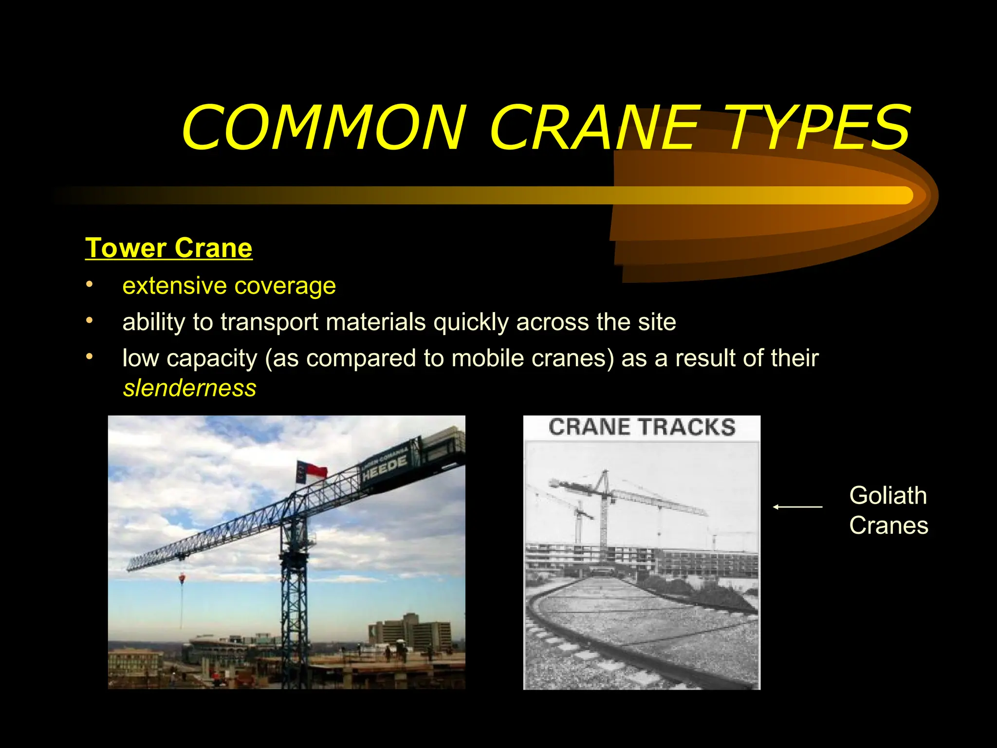
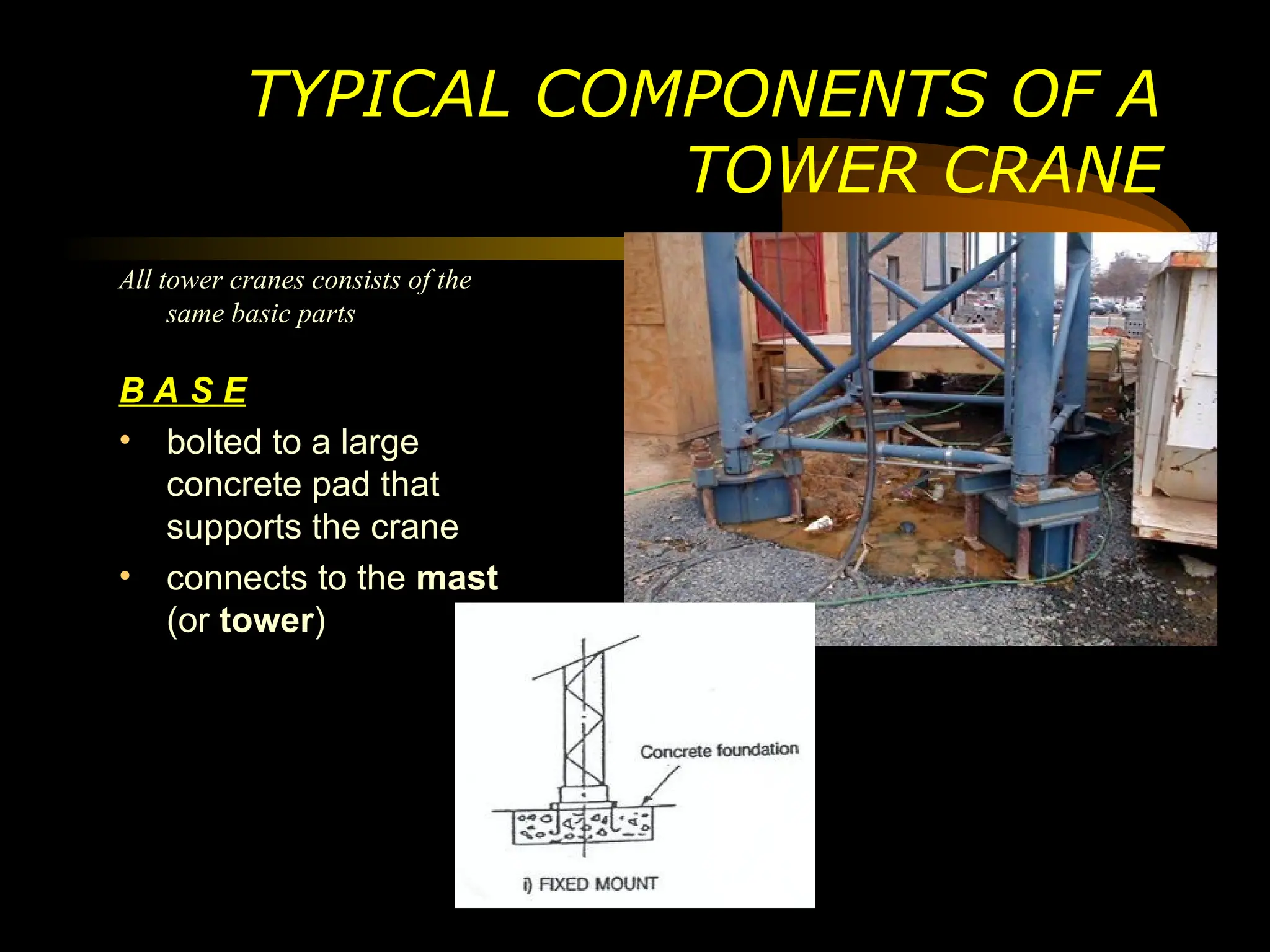
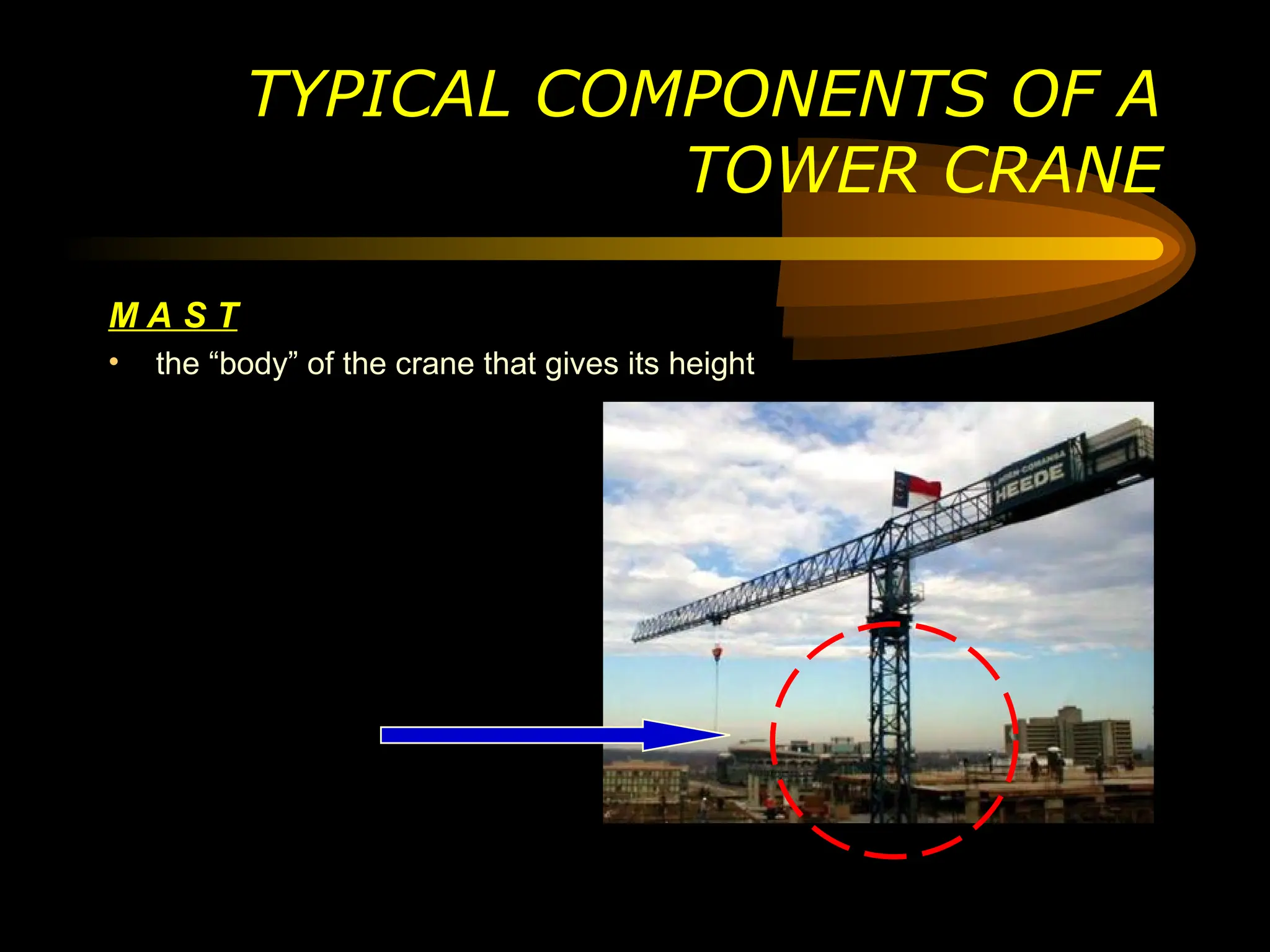
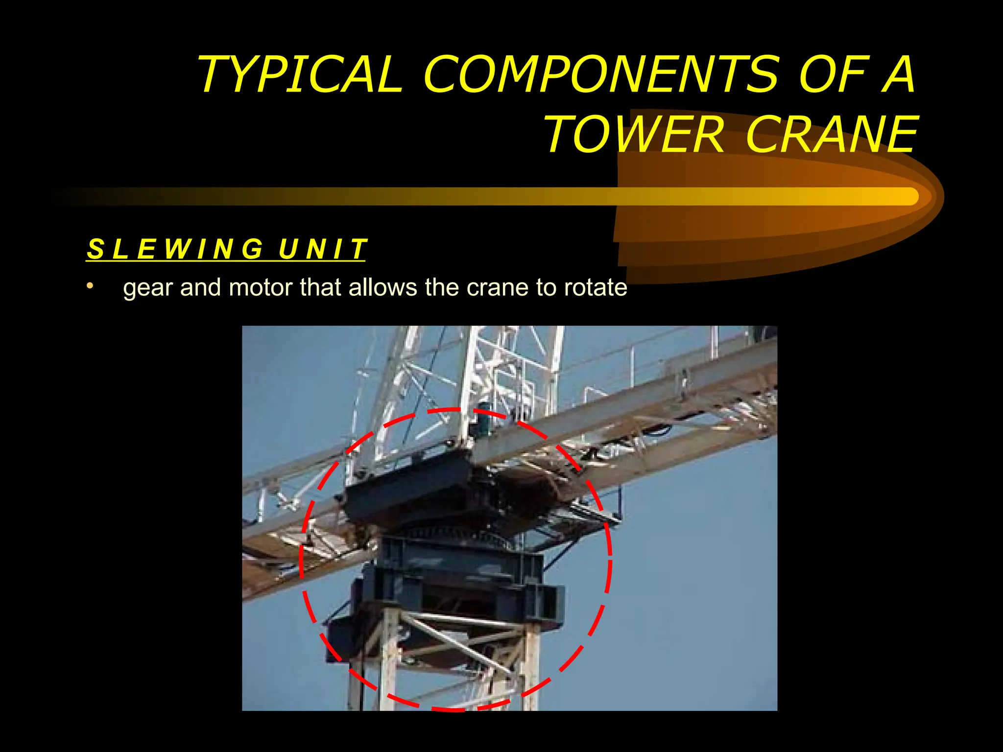
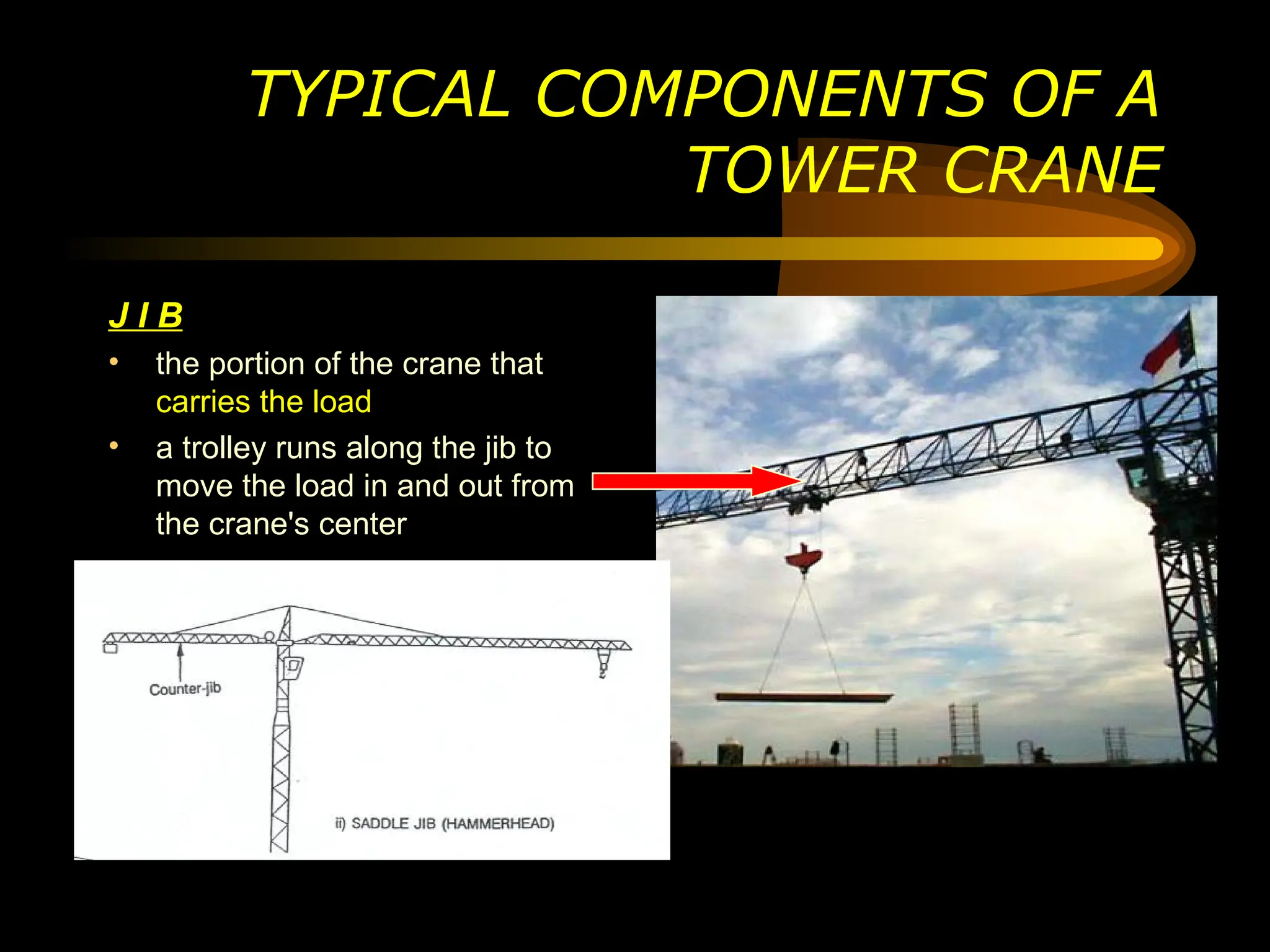
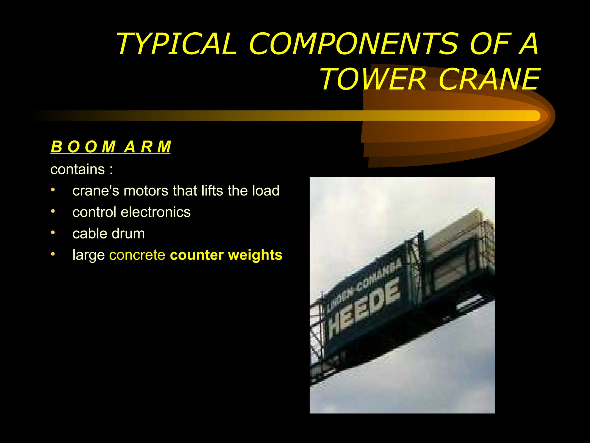
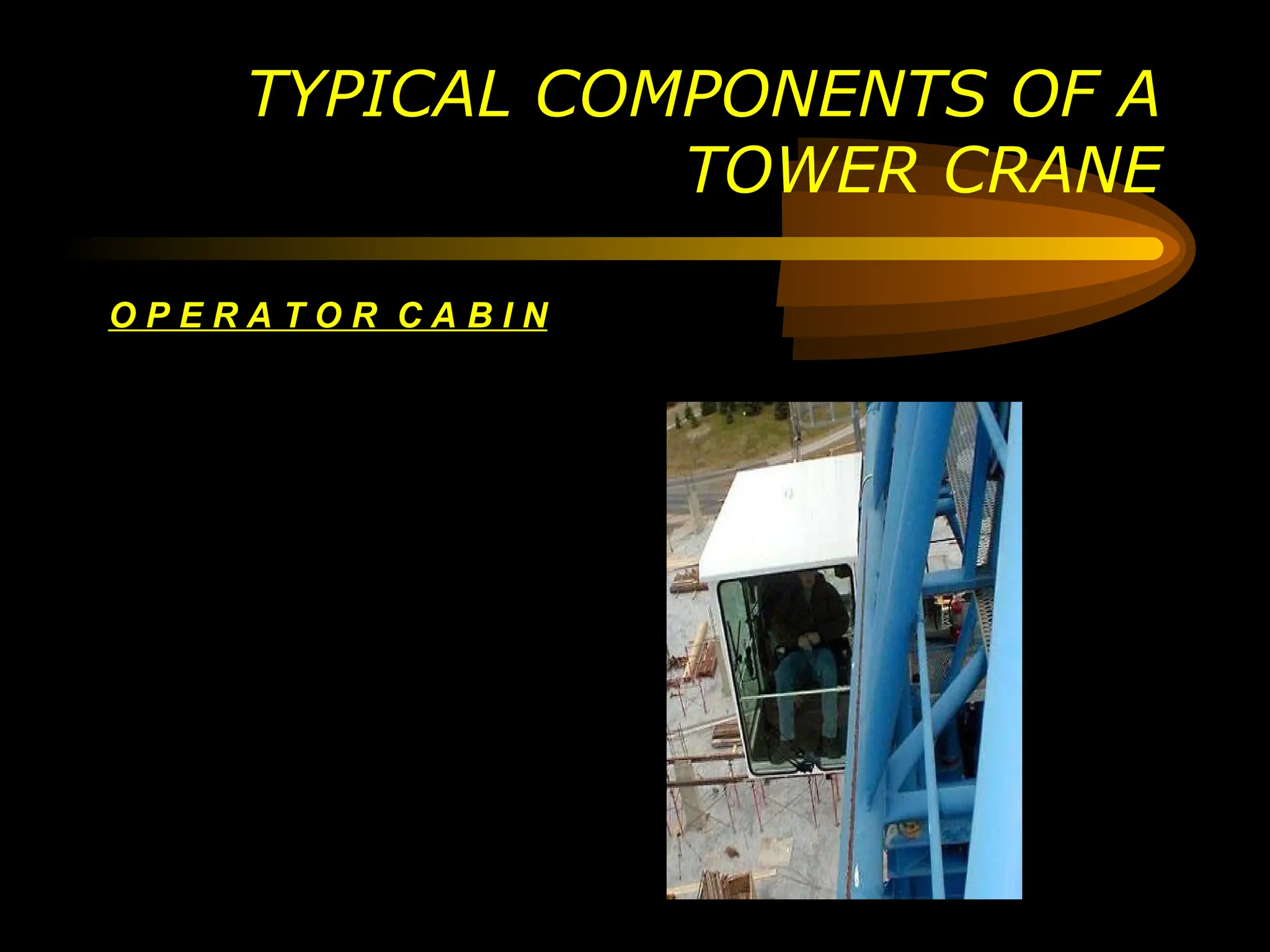
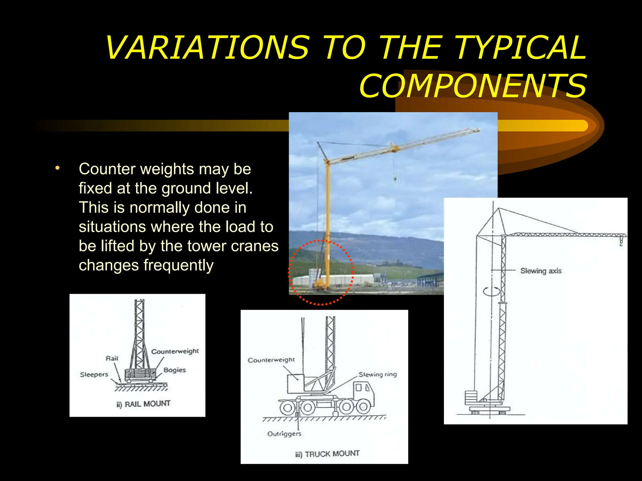
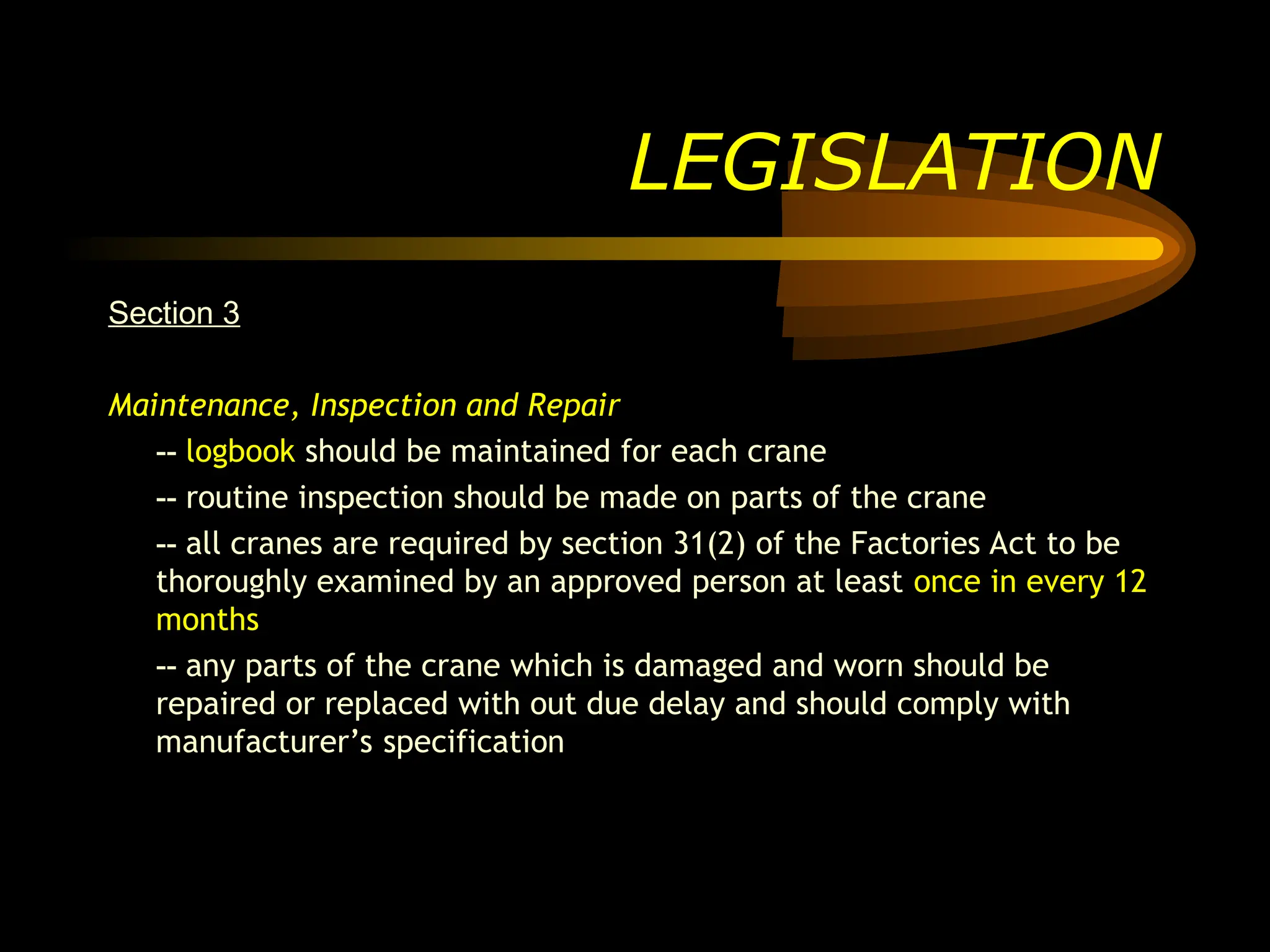
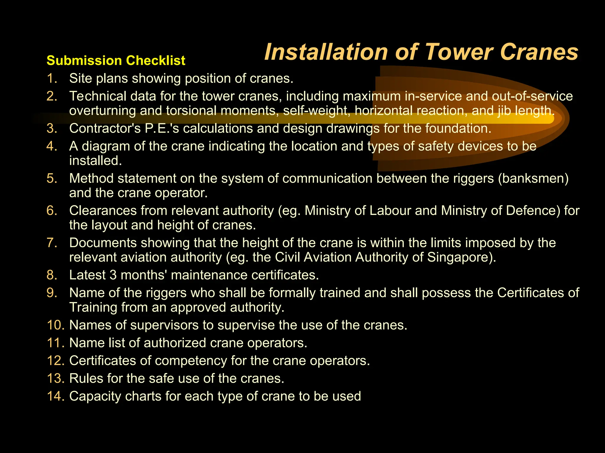
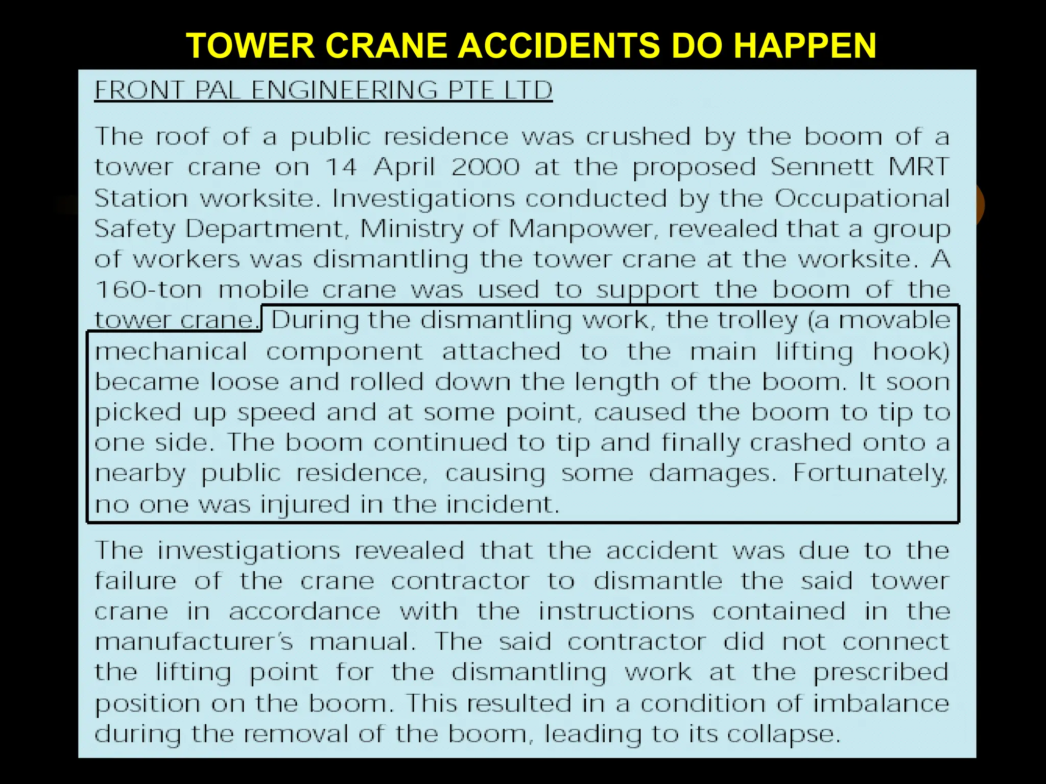
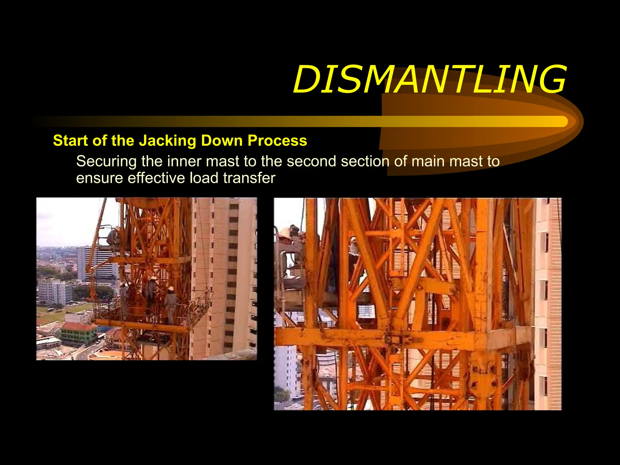
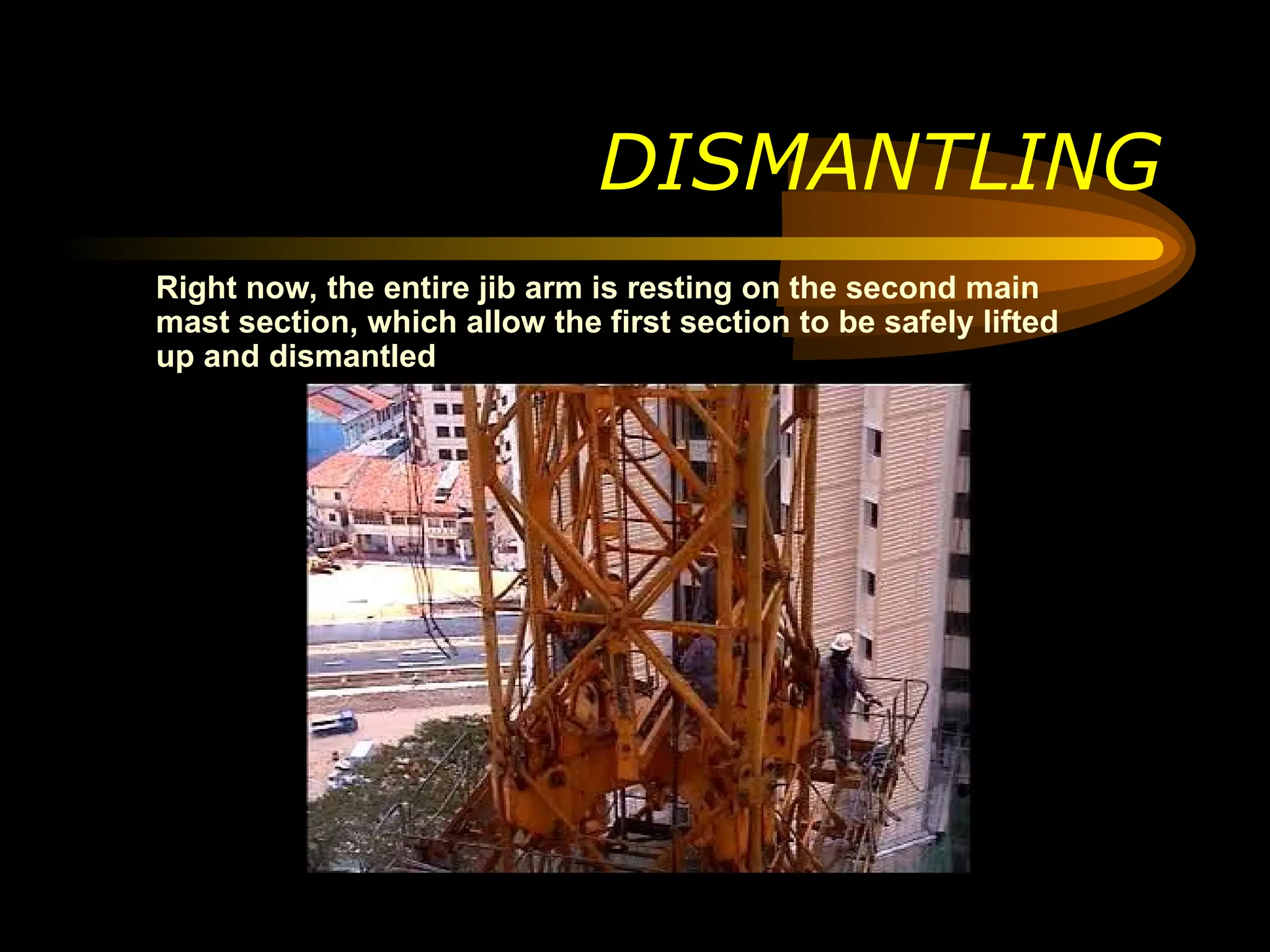
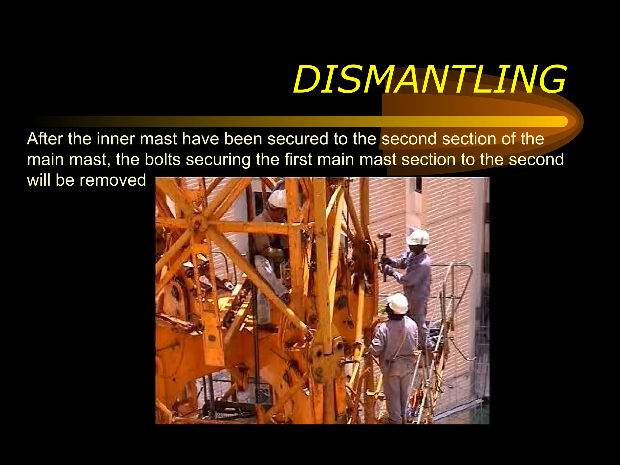
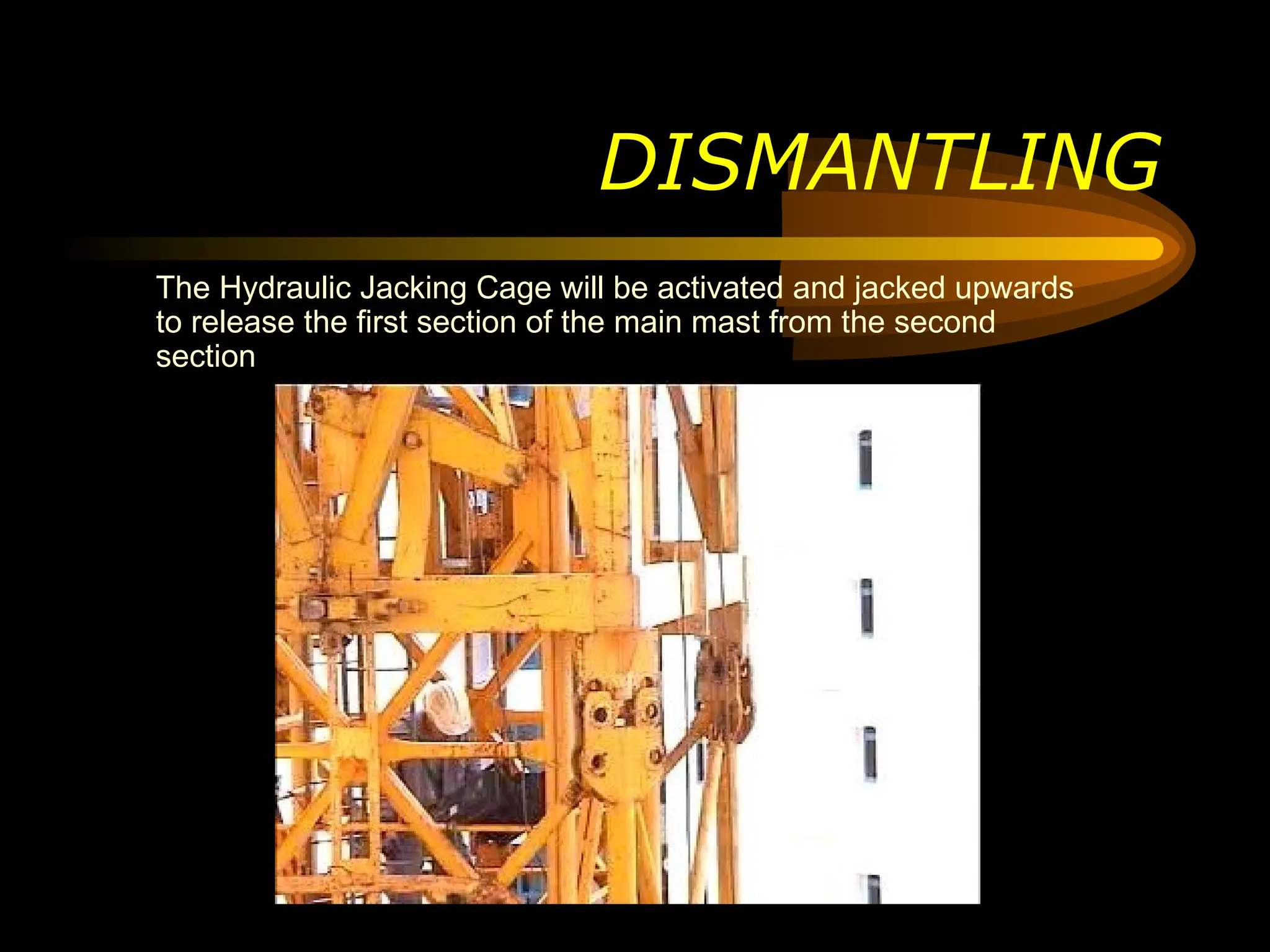
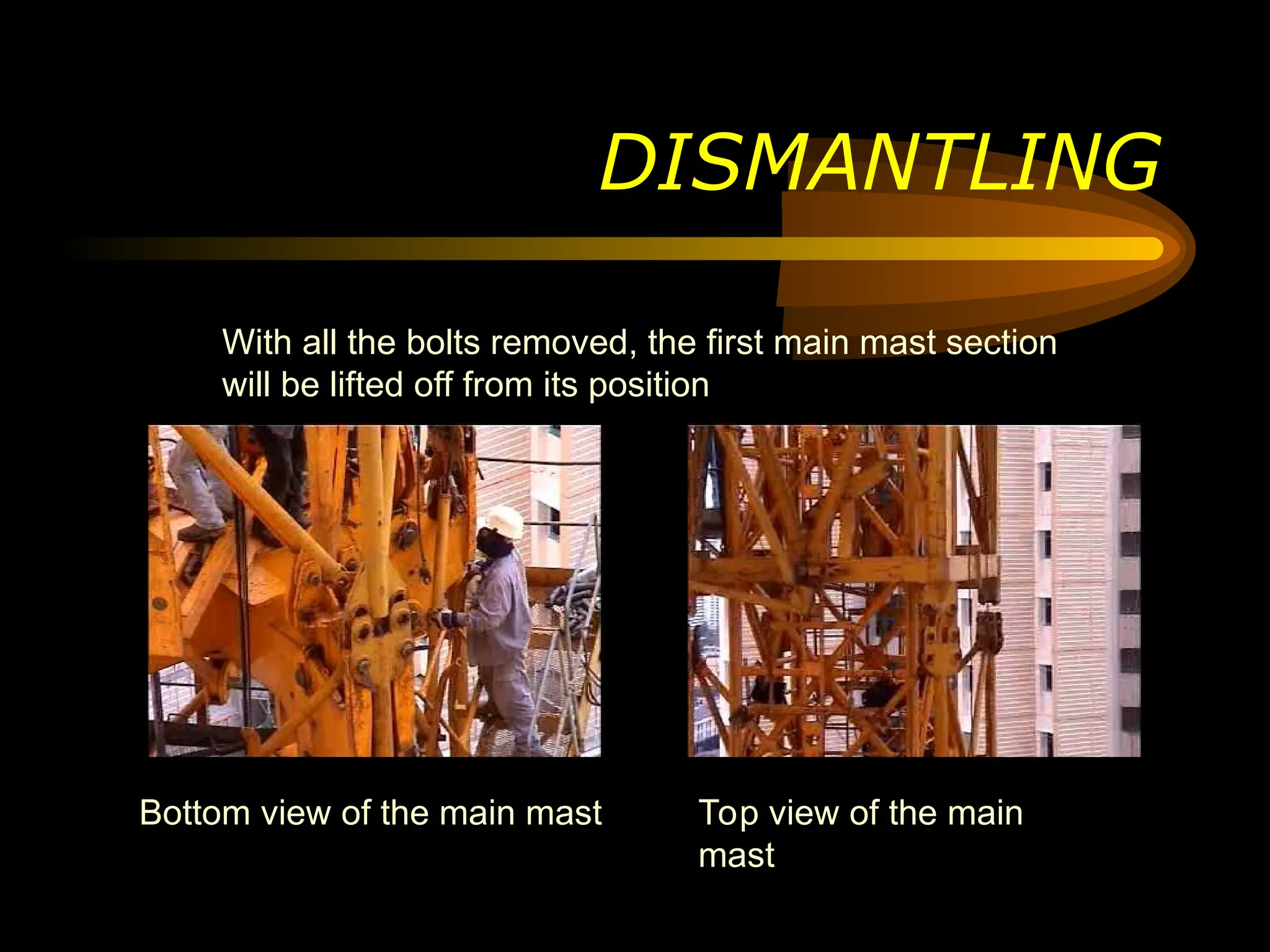
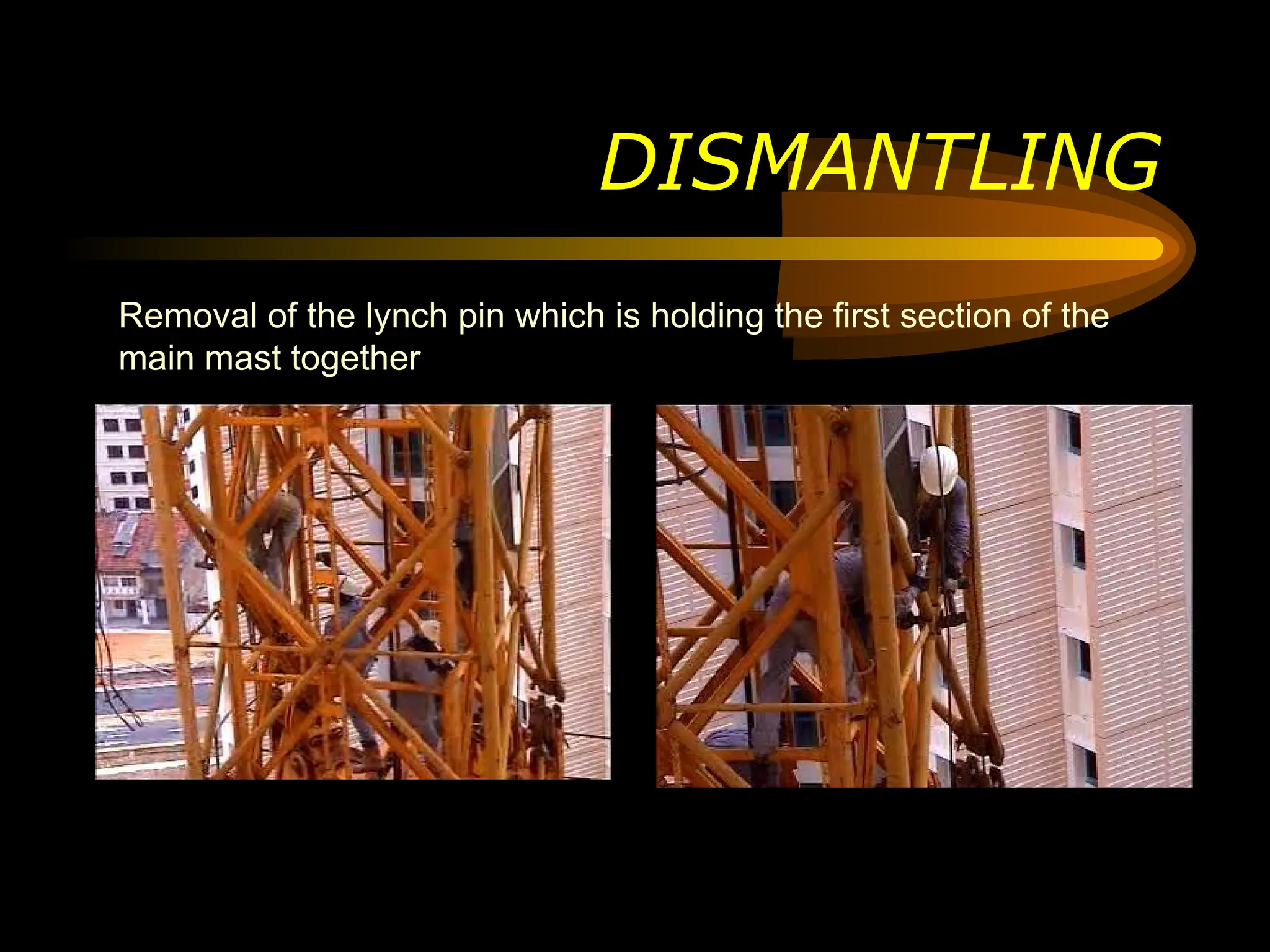
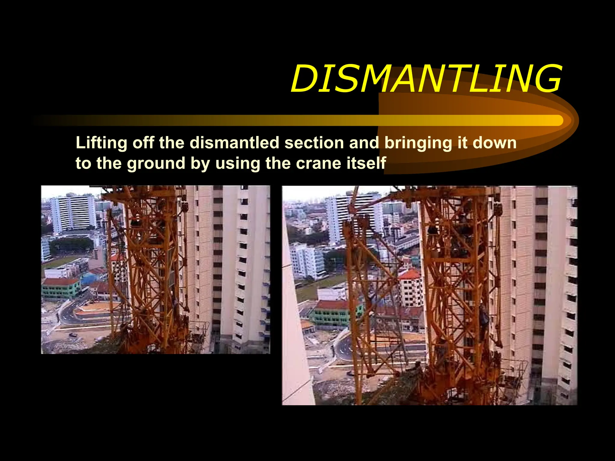
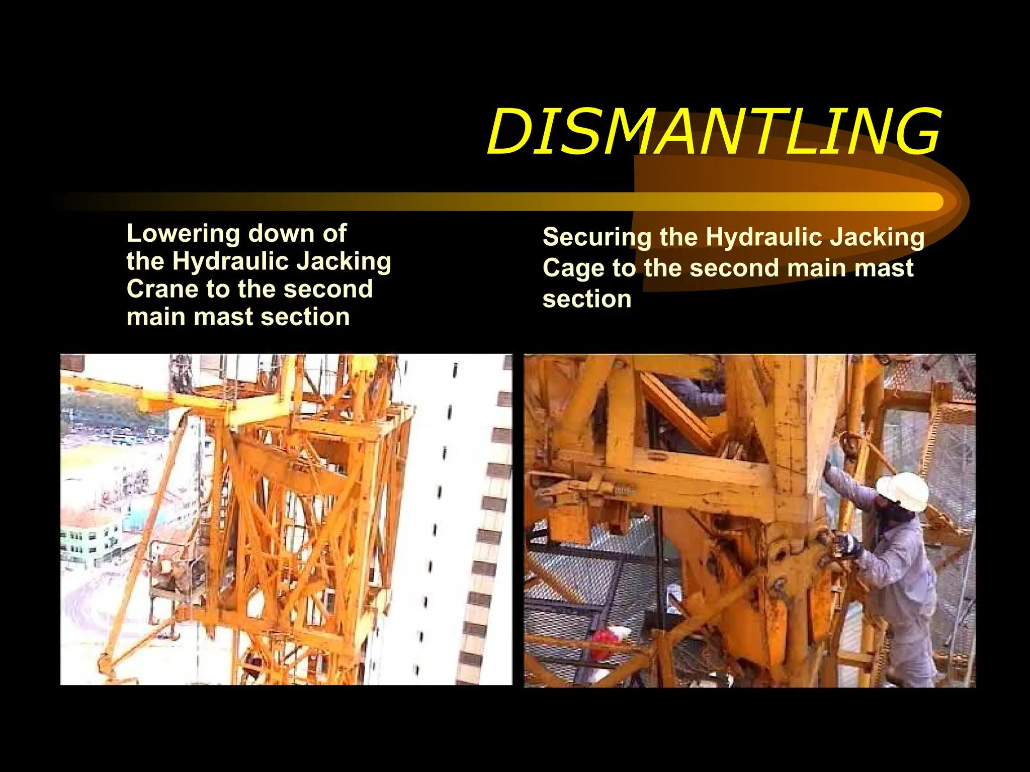
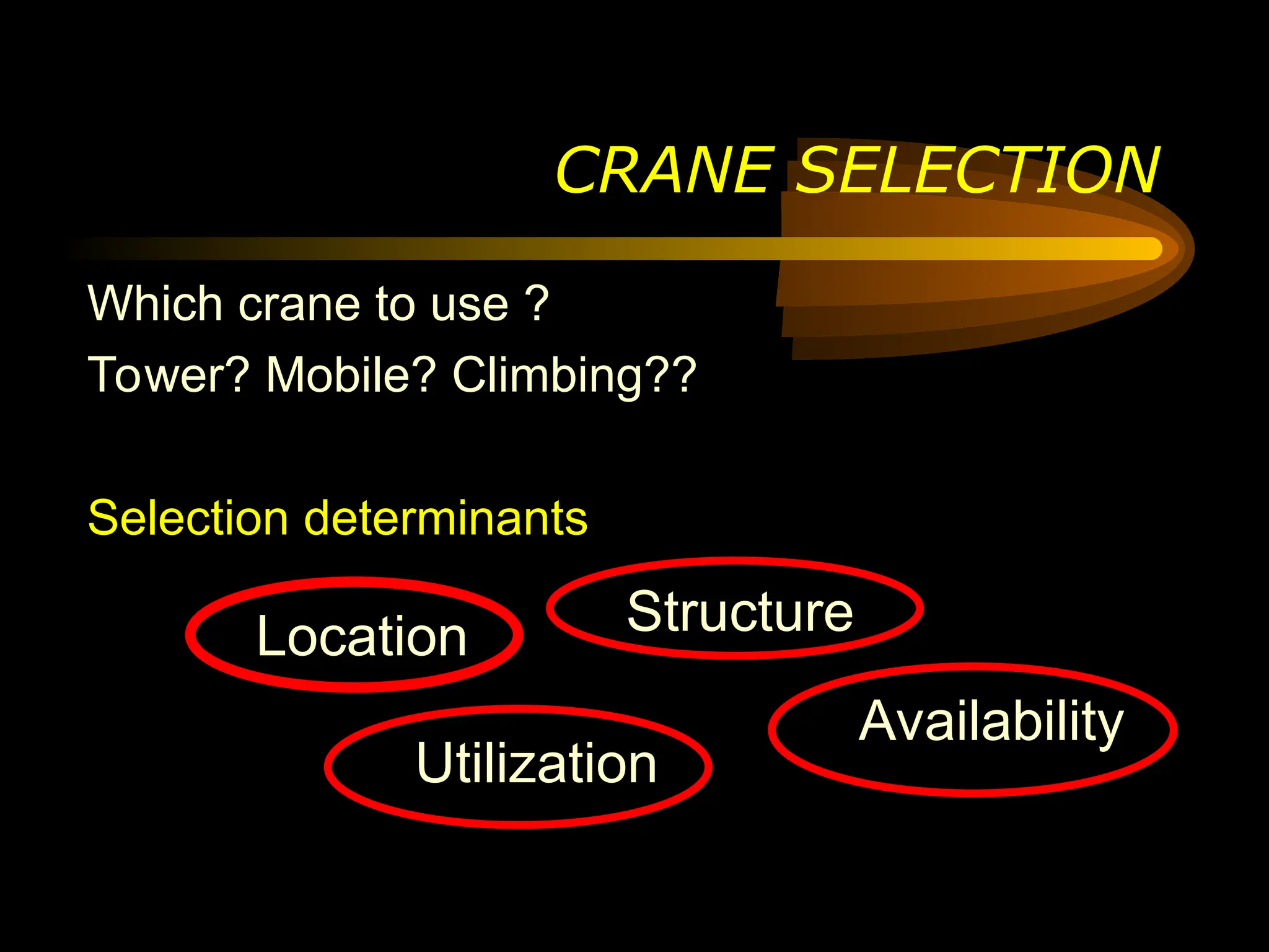
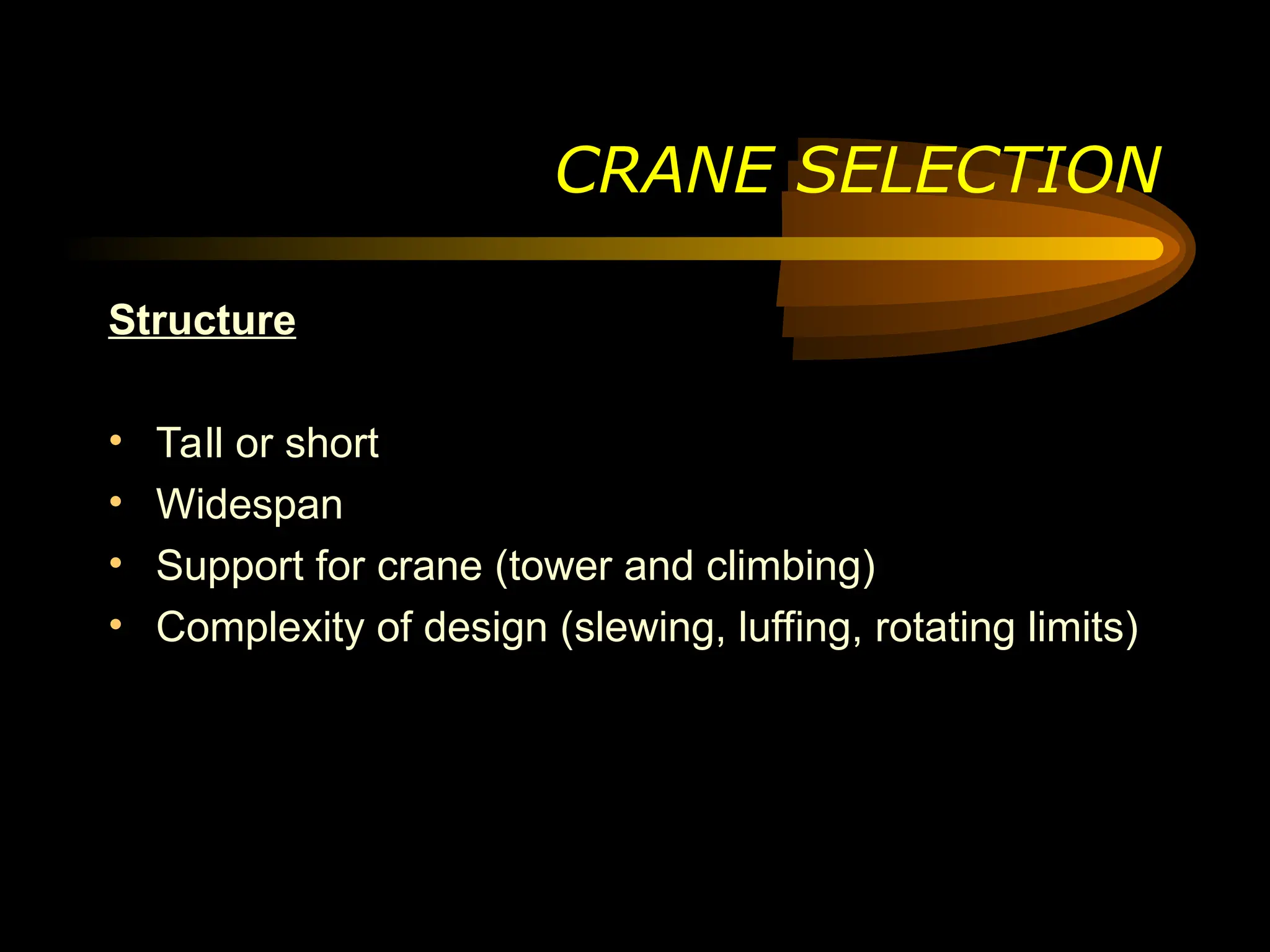
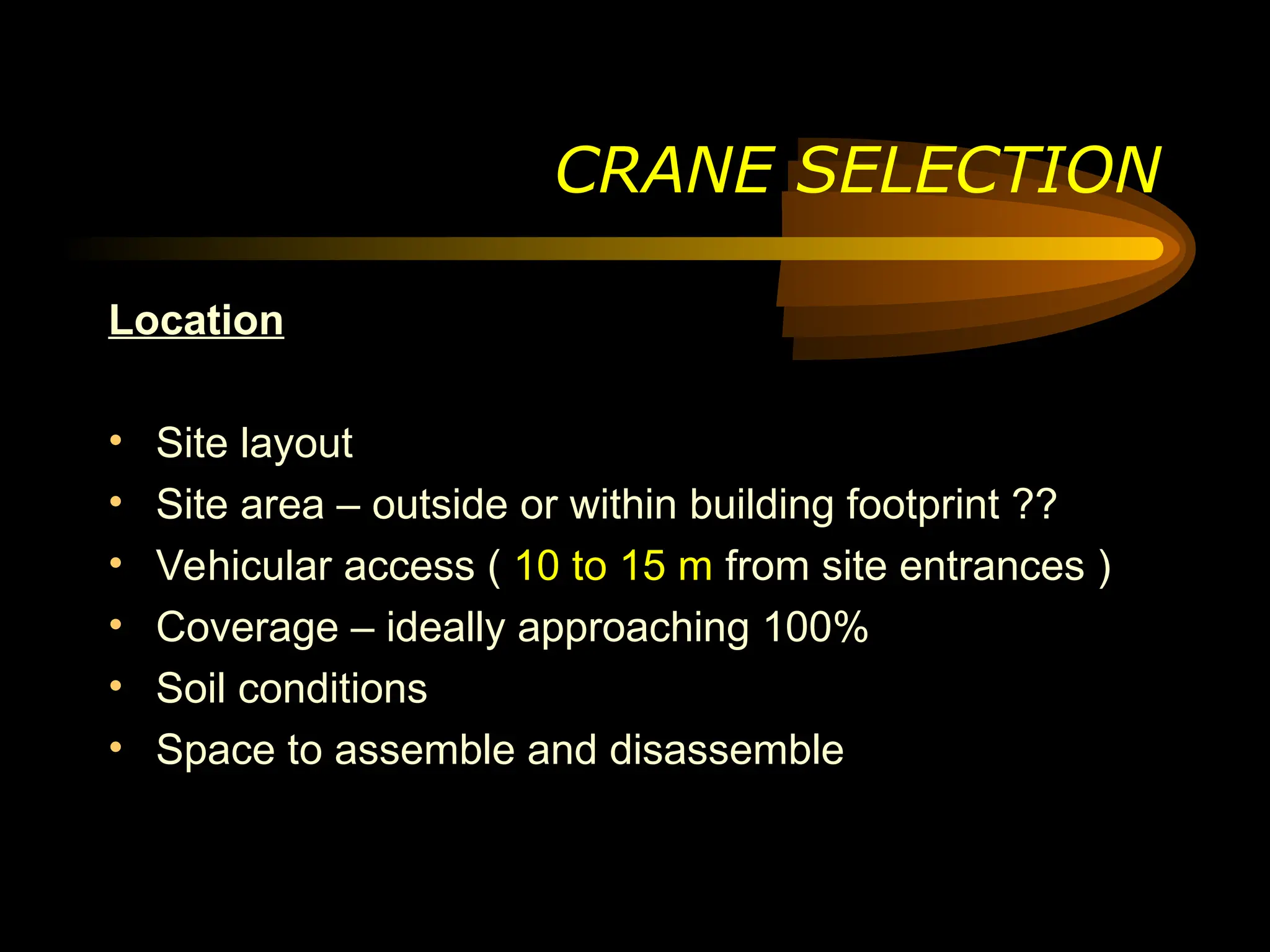
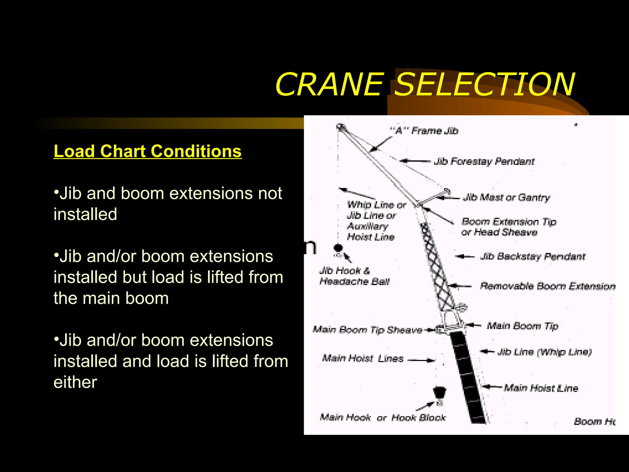
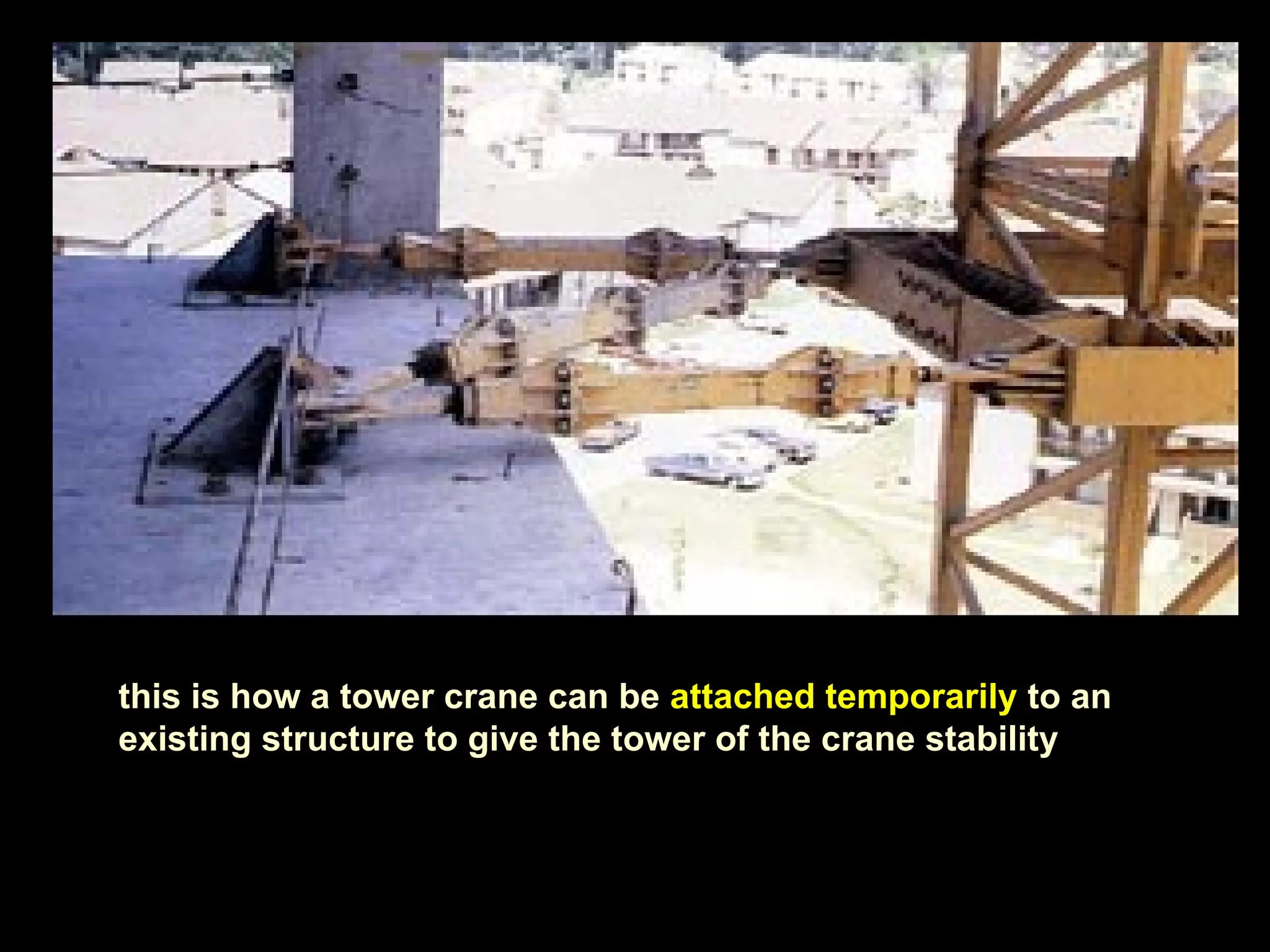
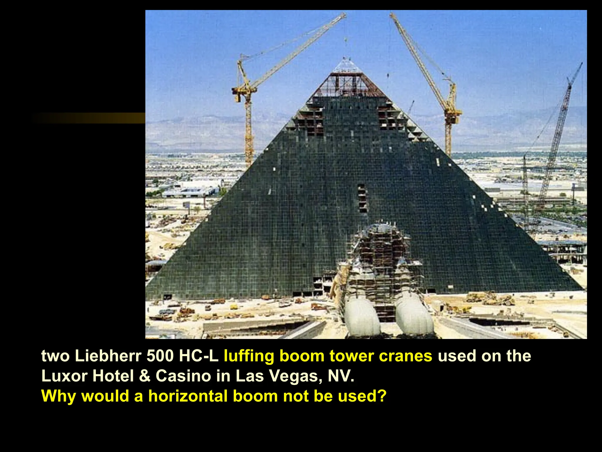
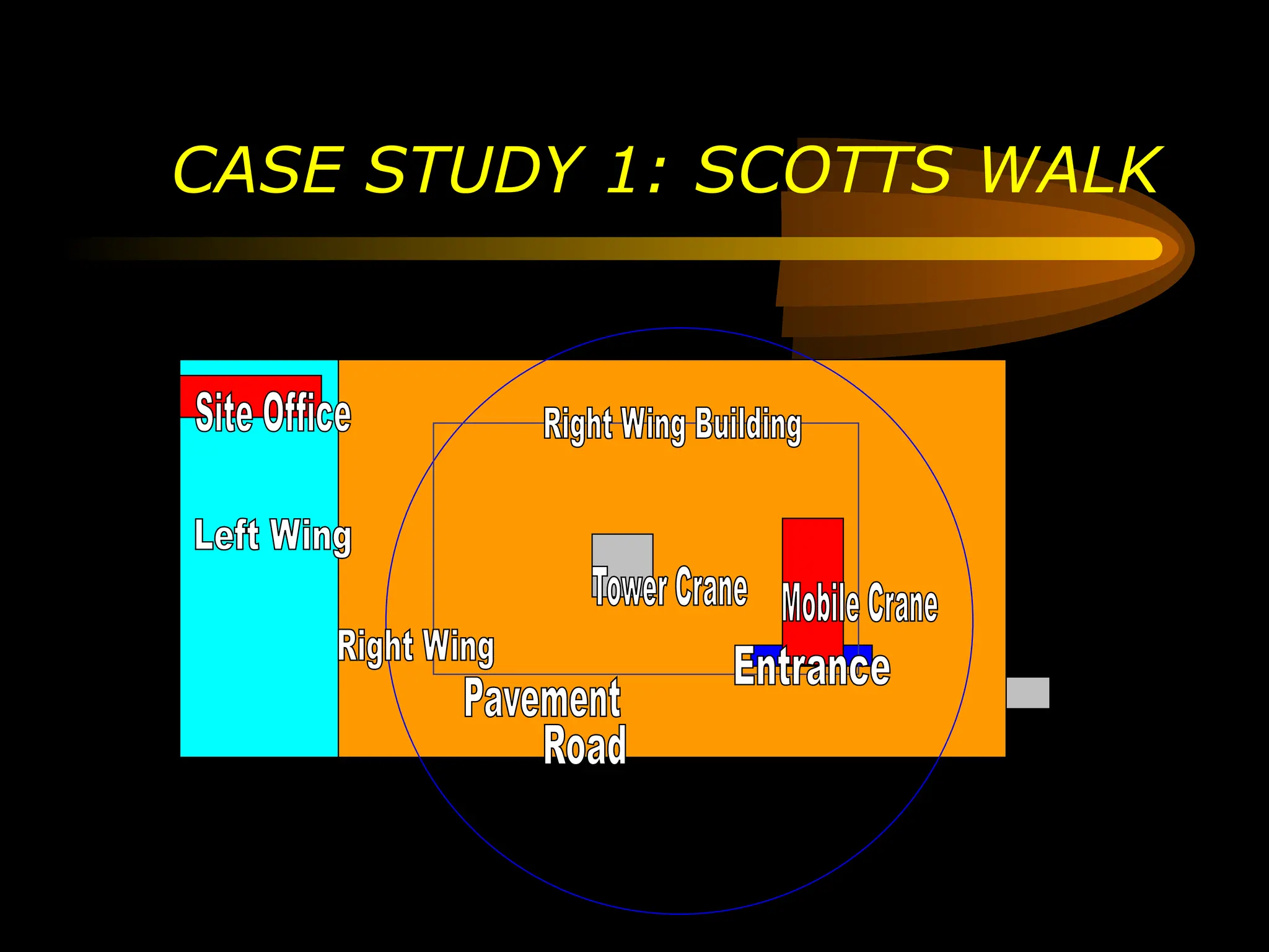
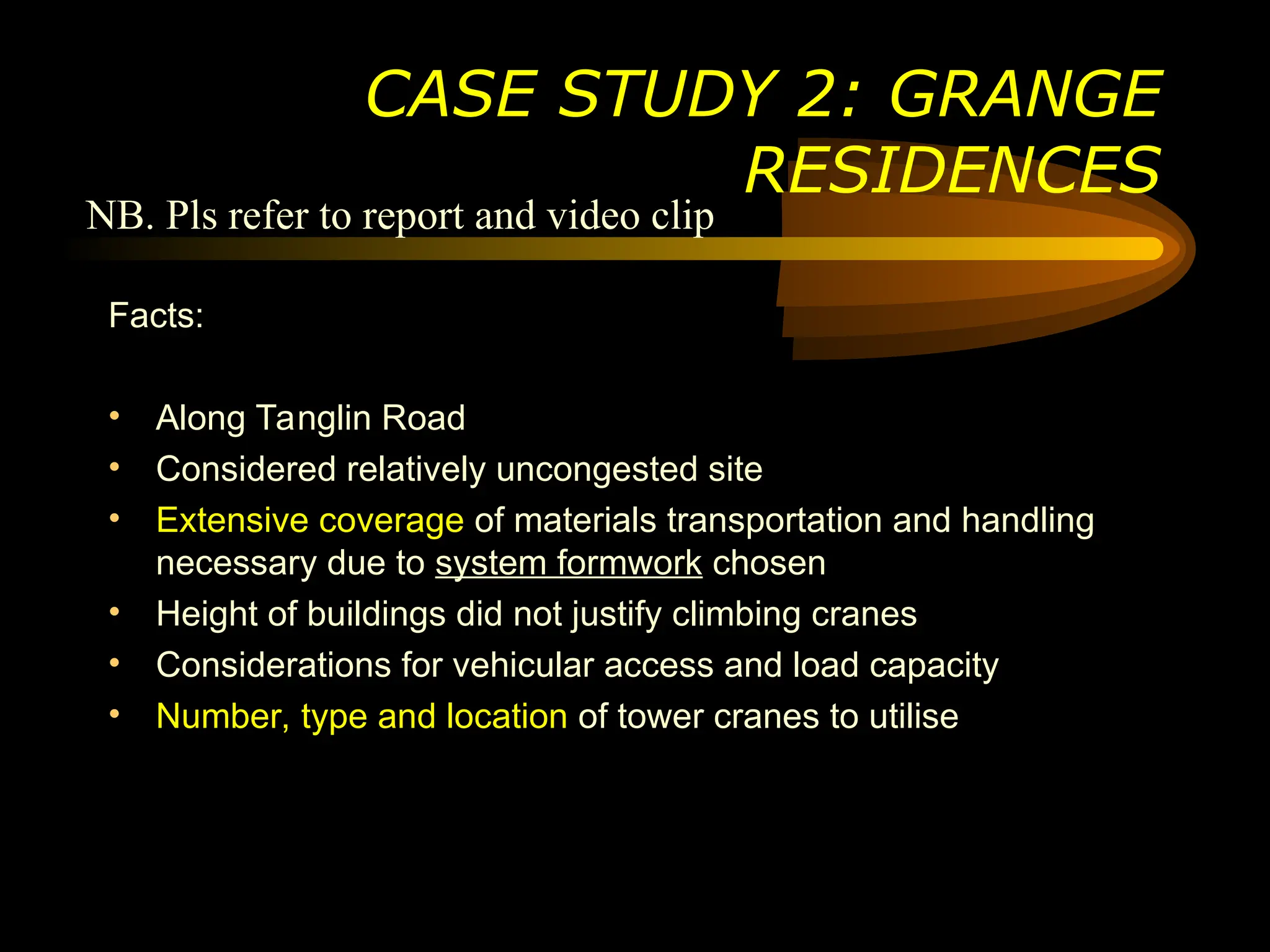
Discuss the Erection of Tower
Cranes.
Justify the selection in terms of
size, location, and erection
methods
COMMON CRANE TYPES
Truck Mounted Cranes
• loading / unloading purposes
• may be attached with telescopic or lattice arms, slewing or fixed
COMMON CRANE TYPES
Mobile Crane
• normally fitted with strut (lattice) or hydraulic
jibs
• common for them to come with a flying jib as
well
• difficulties in accurate positioning of
components such as cooling towers at top of
building
• limited site coverage
COMMON CRANE TYPES
Climbing Crane
• climb up a shaft within a building
using a limited number of mast
sections
• strategic coverage yet maximizing
land use in congested sites
COMMON CRANE TYPES
Gantry Crane
• jib supported on a 4-legged portal carried on rails with adjustable height
for flexibility
• normally used for material handling in the construction of caissons
COMMON CRANE TYPES
Tower Crane
• extensive coverage
• ability to transport materials quickly across the site
• low capacity (as compared to mobile cranes) as a result of their
slenderness
Goliath
Cranes
TYPICAL COMPONENTS OF A
TOWER CRANE
All tower cranes consists of the
same basic parts
B A S E
• bolted to a large
concrete pad that
supports the crane
• connects to the mast
(or tower)
M A S T
• the “body” of the crane that gives its height
TYPICAL COMPONENTS OF A
TOWER CRANE
S L E W I N G U N I T
• gear and motor that allows the crane to rotate
TYPICAL COMPONENTS OF A
TOWER CRANE
J I B
• the portion of the crane that
carries the load
• a trolley runs along the jib to
move the load in and out from
the crane's center
TYPICAL COMPONENTS OF A
TOWER CRANE
B O O M A R M
contains :
• crane's motors that lifts the load
• control electronics
• cable drum
• large concrete counter weights
TYPICAL COMPONENTS OF A
TOWER CRANE
O P E R A T O R C A B I N
TYPICAL COMPONENTS OF A
TOWER CRANE
VARIATIONS TO THE TYPICAL
COMPONENTS
• Counter weights may be
fixed at the ground level.
This is normally done in
situations where the load to
be lifted by the tower cranes
changes frequently
Derricking (Luffing) Crane
• exceptionally tall buildings or in very restricted spaces
• able to slew through 360o
under load at only 8m slewing radius
• compact slewing radius and steep jib angle (between 15° and 70°)
• suitable for use on confined sites where several cranes have overlapping
slewing radii
VARIATIONS TO THE TYPICAL
COMPONENTS
The H series The TT series The K series The A series
H, TT and K series of bottom-slewing cranes are designed
as fast-erecting cranes and are ideal for small, narrow
building sites. Lifting capacities of up to 120 metric ton can
be handled with hook heights of up to 34m
DIFFERENT SERIES OF TOWER
CRANES
DIFFERENT SERIES OF TOWER
CRANES
The LC series The EC / EL series The EC-B series The EC-H series
The LC and EC / EL- top-slewing cranes are particularly easy to
transport and assemble. The construction series ranges from 30
to 100 metric ton, with trolley jib extensions from 30.0 to 52.5m
The top-slewing cranes in the HC series are general-purpose cranes for
use in medium- to large-scale construction projects of all kinds. The
series covers capacities from 800 to 5,000 metric ton with luffing or
telescopic jib lengths of up to 100m; maximum loads of 80 ton and free
traveling hook heights of up to 110m.
DIFFERENT SERIES OF TOWER
CRANES
The HC series The HC-L series The HC-T series The HC-K series
CP 62: 1995 Code of Practice for safe use of tower cranes
Section 2
Operational Conditions
• Sitting and General Safety Considerations
-- adequate soil bearing capacity
-- should not encroach upon public areas
-- cranes must not be in the way of aircraft flight path
-- adequately grounded and protected from lightning
LEGISLATION
LEGISLATION
Operational Conditions
• Stability
-- data on the maximum forces acting at the crane’s base
-- crane’s dead weight, weight of attachments and the maximum dynamic
forces
-- estimates on wind load
-- must be plumped
• Proximity Hazards
-- site boundaries
-- slewing limits switches could be used to restrict jib movements
-- trolleying limits switches
-- jib of higher crane must be at least 2m above the top of lower crane when 2
or more cranes are used
-- jib of one crane should not interfere with the mast of another crane
LEGISLATION
Operational Conditions
• Erection and Dismantling
-- sufficient working space
-- inspection by competent engineer before erection and by relevant
authorities
-- check all bolts, locking devices, wire ropes, indicators, alarms, other
safety devices, ladders, platforms, walkways, handrails, etc
-- anchorage should be used when the crane exceeded free standing
height
-- radius indicator and load capacity chart must be fixed
-- load limit switch must be fixed
LEGISLATION
• Operation and Control
-- should not be used for dragging and pulling of load, inclined load,
piling work, demolition
-- load capacity chart
-- operator and signaler
-- when crane is unattended, all loads must be unloaded and hook
raised to highest position and minimum radius
-- tag lines
Section 3
Maintenance, Inspection and Repair
-- logbook should be maintained for each crane
-- routine inspection should be made on parts of the crane
-- all cranes are required by section 31(2) of the Factories Act to be
thoroughly examined by an approved person at least once in every 12
months
-- any parts of the crane which is damaged and worn should be
repaired or replaced with out due delay and should comply with
manufacturer’s specification
LEGISLATION
Installation of Tower Cranes
Submission Checklist
1. Site plans showing position of cranes.
2. Technical data for the tower cranes, including maximum in-service and out-of-service
overturning and torsional moments, self-weight, horizontal reaction, and jib length.
3. Contractor's P.E.'s calculations and design drawings for the foundation.
4. A diagram of the crane indicating the location and types of safety devices to be
installed.
5. Method statement on the system of communication between the riggers (banksmen)
and the crane operator.
6. Clearances from relevant authority (eg. Ministry of Labour and Ministry of Defence) for
the layout and height of cranes.
7. Documents showing that the height of the crane is within the limits imposed by the
relevant aviation authority (eg. the Civil Aviation Authority of Singapore).
8. Latest 3 months' maintenance certificates.
9. Name of the riggers who shall be formally trained and shall possess the Certificates of
Training from an approved authority.
10. Names of supervisors to supervise the use of the cranes.
11. Name list of authorized crane operators.
12. Certificates of competency for the crane operators.
13. Rules for the safe use of the cranes.
14. Capacity charts for each type of crane to be used
Guide to Carrying out Restricted Activities within the
Railway Protection and Safety Zones
TOWER CRANE ACCIDENTS DO HAPPEN
Code of Practice, Safety and Health of Construction
Worksites Part I, 1985
Chapter 9 – Lifting appliances and Equipment
Section 5.3 and 5.6
• Structure
-- Crane should be made from materials that absorb shock such as mild
steel
-- Cabin should be made of fire resisting material and provided with a
fire extinguisher
-- Access to the cabin should be from a safe place in the crane
LEGISLATION
LEGISLATION
Section 5.3 and 5.6
• Anchorage and ballast
-- Every fixed crane should either be securely anchored or be
adequately weighed by suitable ballast firmly secured to ensure stability
-- Counterweights should be so arranged that they do not subject the
backstays, sleepers or pivots to excessive strain
LEGISLATION
Section 5.3 and 5.6
• Load and radius indicator
-- The maximum permitted angle of inclination of the crane jib must be
clearly marked on the crane
• Operation
-- Jib cranes should not be moved or operated in dangerous proximity
to electric power lines
Erection Procedures
(refer to Video Clip and Report for
comprehensive guide)
Dismantling Procedures
(for telescopic, self jacking tower crane)
Hydraulic
Jacking Cage
Inner mast
Outer mast
Hydraulic
Jacking Cage
jacks inner mast
downwards
First section
bolts released
Bolts to secure
the inner mast to
the second
section of the
outer mast
First section mast
will be removed
Hydraulic
Jacking Cage
will be jacked
downwards
Inner mast is jacked
downwards
Hydraulic Jacking
Cage is now in
position of first
section
Case Study : Proposed 30th
storey HDB site along
Joo Chiat Road
DISMANTLING
•Singapore’s first pre-cast water tanks
to be installed in HDB flats
•Water tanks to be positioned on top of
flats
•Heavy load capacity profile
•K-4 series self-jacking crane chosen
Fitting of the Hydraulic Jacking Cage to the inner mast
The Hydraulic Jacking Cage is fitted to the inner mast by using bolts
and the sections of the Hydraulic Jacking Cage are hoisted up by the
crane itself
DISMANTLING
Start of the Jacking Down Process
Securing the inner mast to the second section of main mast to
ensure effective load transfer
DISMANTLING
DISMANTLING
Right now, the entire jib arm is resting on the second main
mast section, which allow the first section to be safely lifted
up and dismantled
DISMANTLING
After the inner mast have been secured to the second section of the
main mast, the bolts securing the first main mast section to the second
will be removed
DISMANTLING
The Hydraulic Jacking Cage will be activated and jacked upwards
to release the first section of the main mast from the second
section
DISMANTLING
With all the bolts removed, the first main mast section
will be lifted off from its position
Bottom view of the main mast Top view of the main
mast
DISMANTLING
Removal of the lynch pin which is holding the first section of the
main mast together
DISMANTLING
Lifting off the dismantled section and bringing it down
to the ground by using the crane itself
DISMANTLING
Lowering down of
the Hydraulic Jacking
Crane to the second
main mast section
Securing the Hydraulic Jacking
Cage to the second main mast
section
Which crane to use ?
Tower? Mobile? Climbing??
Selection determinants
CRANE SELECTION
Location Structure
Utilization
Availability
CRANE SELECTION
Structure
• Tall or short
• Widespan
• Support for crane (tower and climbing)
• Complexity of design (slewing, luffing, rotating limits)
Location
• Site layout
• Site area – outside or within building footprint ??
• Vehicular access ( 10 to 15 m from site entrances )
• Coverage – ideally approaching 100%
• Soil conditions
• Space to assemble and disassemble
CRANE SELECTION
Utilization
Crane Configuration
Two main determinants
• Lifting weight
• Lifting distance – height and reach
Use load charts to determine crane configuration
capabilities
CRANE SELECTION
CRANE SELECTION
Load Chart Conditions
•Jib and boom extensions not
installed
•Jib and/or boom extensions
installed but load is lifted from
the main boom
•Jib and/or boom extensions
installed and load is lifted from
either
Factors Affecting Conditions
• Weight to be lifted
• Crane Base Geometry & Configuration
• Crane Configuration
• Quadrant(s) of Operation (mobile crane)
• Boom Length
• Load Radius
• Deductions from Gross Capacity
CRANE SELECTION
Availability
• Financial resources
• Market availability
CRANE SELECTION
a Liebherr 390HC horizontal jib tower
crane located in Las Vegas, NV on the
Stratosphere (tallest structure in
Nevada); final hook height of 1120'; it is
being used to construct the roller
coaster and radio tower on the top of
this restaurant. It has a forward jib and a
rear jib with a trolley running on the
forward jib controlling the hoisting cable
In 1995 Sheedy received
the SC&RA Rigging Job of
the Year Award for
removing a Liebherr 390
HC tower crane from the
Stratosphere Tower in Las
Vegas, Nevada
In order to remove the tower crane, at an
elevation of 1200 ft., a detailed engineering
plan was developed and implemented
a Liebherr 550C rail-traveler horizontal jib tower crane located at
Houston Intercontinental Airport, Houston, TX; the tracks provide a
much greater working range; the construction of the tracks is quite
substantial and provision has to be made for use or removal when the
crane is removed
this is how a tower crane can be attached temporarily to an
existing structure to give the tower of the crane stability
two Liebherr 500 HC-L luffing boom tower cranes used on the
Luxor Hotel & Casino in Las Vegas, NV.
Why would a horizontal boom not be used?
Need for Tower Crane?
Facts and figures:
• The extension of the Royal Hotel is on the right wing of the site.
• Left wing is for A&A.
• Right wing had been demolished for a new 5-storey extension
of the Royal Hotel.
• Site dimension approx 40m by 30m.
• Piling had already been done.
• Congested Site.
• Tower Crane is needed, as congested site do not allow easy
movement of mobile crane
CASE STUDY 1: SCOTTS WALK
NB. Pls refer to report and video clip
CASE STUDY 1: SCOTTS WALK
Facts:
• Along Tanglin Road
• Considered relatively uncongested site
• Extensive coverage of materials transportation and handling
necessary due to system formwork chosen
• Height of buildings did not justify climbing cranes
• Considerations for vehicular access and load capacity
• Number, type and location of tower cranes to utilise
CASE STUDY 2: GRANGE
RESIDENCES
NB. Pls refer to report and video clip
CASE STUDY 2: GRANGE
RESIDENCES
Blk A
Blk B
Blk C
Blk A
Blk B
Blk C
Blk A Blk B
Blk C
Blk A Blk B
Blk C
The End

Tower Crane PPT (Lite Version).ppt To be utilized after taking permission from initiator for his copyright

  • 1.
    Discuss the Erectionof Tower Cranes. Justify the selection in terms of size, location, and erection methods
  • 2.
    COMMON CRANE TYPES TruckMounted Cranes • loading / unloading purposes • may be attached with telescopic or lattice arms, slewing or fixed
  • 3.
    COMMON CRANE TYPES MobileCrane • normally fitted with strut (lattice) or hydraulic jibs • common for them to come with a flying jib as well • difficulties in accurate positioning of components such as cooling towers at top of building • limited site coverage
  • 4.
    COMMON CRANE TYPES ClimbingCrane • climb up a shaft within a building using a limited number of mast sections • strategic coverage yet maximizing land use in congested sites
  • 5.
    COMMON CRANE TYPES GantryCrane • jib supported on a 4-legged portal carried on rails with adjustable height for flexibility • normally used for material handling in the construction of caissons
  • 6.
    COMMON CRANE TYPES TowerCrane • extensive coverage • ability to transport materials quickly across the site • low capacity (as compared to mobile cranes) as a result of their slenderness Goliath Cranes
  • 7.
    TYPICAL COMPONENTS OFA TOWER CRANE All tower cranes consists of the same basic parts B A S E • bolted to a large concrete pad that supports the crane • connects to the mast (or tower)
  • 8.
    M A ST • the “body” of the crane that gives its height TYPICAL COMPONENTS OF A TOWER CRANE
  • 9.
    S L EW I N G U N I T • gear and motor that allows the crane to rotate TYPICAL COMPONENTS OF A TOWER CRANE
  • 10.
    J I B •the portion of the crane that carries the load • a trolley runs along the jib to move the load in and out from the crane's center TYPICAL COMPONENTS OF A TOWER CRANE
  • 11.
    B O OM A R M contains : • crane's motors that lifts the load • control electronics • cable drum • large concrete counter weights TYPICAL COMPONENTS OF A TOWER CRANE
  • 12.
    O P ER A T O R C A B I N TYPICAL COMPONENTS OF A TOWER CRANE
  • 13.
    VARIATIONS TO THETYPICAL COMPONENTS • Counter weights may be fixed at the ground level. This is normally done in situations where the load to be lifted by the tower cranes changes frequently
  • 14.
    Derricking (Luffing) Crane •exceptionally tall buildings or in very restricted spaces • able to slew through 360o under load at only 8m slewing radius • compact slewing radius and steep jib angle (between 15° and 70°) • suitable for use on confined sites where several cranes have overlapping slewing radii VARIATIONS TO THE TYPICAL COMPONENTS
  • 15.
    The H seriesThe TT series The K series The A series H, TT and K series of bottom-slewing cranes are designed as fast-erecting cranes and are ideal for small, narrow building sites. Lifting capacities of up to 120 metric ton can be handled with hook heights of up to 34m DIFFERENT SERIES OF TOWER CRANES
  • 16.
    DIFFERENT SERIES OFTOWER CRANES The LC series The EC / EL series The EC-B series The EC-H series The LC and EC / EL- top-slewing cranes are particularly easy to transport and assemble. The construction series ranges from 30 to 100 metric ton, with trolley jib extensions from 30.0 to 52.5m
  • 17.
    The top-slewing cranesin the HC series are general-purpose cranes for use in medium- to large-scale construction projects of all kinds. The series covers capacities from 800 to 5,000 metric ton with luffing or telescopic jib lengths of up to 100m; maximum loads of 80 ton and free traveling hook heights of up to 110m. DIFFERENT SERIES OF TOWER CRANES The HC series The HC-L series The HC-T series The HC-K series
  • 18.
    CP 62: 1995Code of Practice for safe use of tower cranes Section 2 Operational Conditions • Sitting and General Safety Considerations -- adequate soil bearing capacity -- should not encroach upon public areas -- cranes must not be in the way of aircraft flight path -- adequately grounded and protected from lightning LEGISLATION
  • 19.
    LEGISLATION Operational Conditions • Stability --data on the maximum forces acting at the crane’s base -- crane’s dead weight, weight of attachments and the maximum dynamic forces -- estimates on wind load -- must be plumped • Proximity Hazards -- site boundaries -- slewing limits switches could be used to restrict jib movements -- trolleying limits switches -- jib of higher crane must be at least 2m above the top of lower crane when 2 or more cranes are used -- jib of one crane should not interfere with the mast of another crane
  • 20.
    LEGISLATION Operational Conditions • Erectionand Dismantling -- sufficient working space -- inspection by competent engineer before erection and by relevant authorities -- check all bolts, locking devices, wire ropes, indicators, alarms, other safety devices, ladders, platforms, walkways, handrails, etc -- anchorage should be used when the crane exceeded free standing height -- radius indicator and load capacity chart must be fixed -- load limit switch must be fixed
  • 21.
    LEGISLATION • Operation andControl -- should not be used for dragging and pulling of load, inclined load, piling work, demolition -- load capacity chart -- operator and signaler -- when crane is unattended, all loads must be unloaded and hook raised to highest position and minimum radius -- tag lines
  • 23.
    Section 3 Maintenance, Inspectionand Repair -- logbook should be maintained for each crane -- routine inspection should be made on parts of the crane -- all cranes are required by section 31(2) of the Factories Act to be thoroughly examined by an approved person at least once in every 12 months -- any parts of the crane which is damaged and worn should be repaired or replaced with out due delay and should comply with manufacturer’s specification LEGISLATION
  • 24.
    Installation of TowerCranes Submission Checklist 1. Site plans showing position of cranes. 2. Technical data for the tower cranes, including maximum in-service and out-of-service overturning and torsional moments, self-weight, horizontal reaction, and jib length. 3. Contractor's P.E.'s calculations and design drawings for the foundation. 4. A diagram of the crane indicating the location and types of safety devices to be installed. 5. Method statement on the system of communication between the riggers (banksmen) and the crane operator. 6. Clearances from relevant authority (eg. Ministry of Labour and Ministry of Defence) for the layout and height of cranes. 7. Documents showing that the height of the crane is within the limits imposed by the relevant aviation authority (eg. the Civil Aviation Authority of Singapore). 8. Latest 3 months' maintenance certificates. 9. Name of the riggers who shall be formally trained and shall possess the Certificates of Training from an approved authority. 10. Names of supervisors to supervise the use of the cranes. 11. Name list of authorized crane operators. 12. Certificates of competency for the crane operators. 13. Rules for the safe use of the cranes. 14. Capacity charts for each type of crane to be used
  • 25.
    Guide to Carryingout Restricted Activities within the Railway Protection and Safety Zones
  • 26.
  • 27.
    Code of Practice,Safety and Health of Construction Worksites Part I, 1985 Chapter 9 – Lifting appliances and Equipment Section 5.3 and 5.6 • Structure -- Crane should be made from materials that absorb shock such as mild steel -- Cabin should be made of fire resisting material and provided with a fire extinguisher -- Access to the cabin should be from a safe place in the crane LEGISLATION
  • 28.
    LEGISLATION Section 5.3 and5.6 • Anchorage and ballast -- Every fixed crane should either be securely anchored or be adequately weighed by suitable ballast firmly secured to ensure stability -- Counterweights should be so arranged that they do not subject the backstays, sleepers or pivots to excessive strain
  • 29.
    LEGISLATION Section 5.3 and5.6 • Load and radius indicator -- The maximum permitted angle of inclination of the crane jib must be clearly marked on the crane • Operation -- Jib cranes should not be moved or operated in dangerous proximity to electric power lines
  • 30.
    Erection Procedures (refer toVideo Clip and Report for comprehensive guide)
  • 31.
    Dismantling Procedures (for telescopic,self jacking tower crane)
  • 32.
  • 33.
    Hydraulic Jacking Cage jacks innermast downwards First section bolts released Bolts to secure the inner mast to the second section of the outer mast
  • 34.
  • 35.
  • 36.
    Inner mast isjacked downwards Hydraulic Jacking Cage is now in position of first section
  • 37.
    Case Study :Proposed 30th storey HDB site along Joo Chiat Road DISMANTLING •Singapore’s first pre-cast water tanks to be installed in HDB flats •Water tanks to be positioned on top of flats •Heavy load capacity profile •K-4 series self-jacking crane chosen
  • 38.
    Fitting of theHydraulic Jacking Cage to the inner mast The Hydraulic Jacking Cage is fitted to the inner mast by using bolts and the sections of the Hydraulic Jacking Cage are hoisted up by the crane itself DISMANTLING
  • 39.
    Start of theJacking Down Process Securing the inner mast to the second section of main mast to ensure effective load transfer DISMANTLING
  • 40.
    DISMANTLING Right now, theentire jib arm is resting on the second main mast section, which allow the first section to be safely lifted up and dismantled
  • 41.
    DISMANTLING After the innermast have been secured to the second section of the main mast, the bolts securing the first main mast section to the second will be removed
  • 42.
    DISMANTLING The Hydraulic JackingCage will be activated and jacked upwards to release the first section of the main mast from the second section
  • 43.
    DISMANTLING With all thebolts removed, the first main mast section will be lifted off from its position Bottom view of the main mast Top view of the main mast
  • 44.
    DISMANTLING Removal of thelynch pin which is holding the first section of the main mast together
  • 45.
    DISMANTLING Lifting off thedismantled section and bringing it down to the ground by using the crane itself
  • 46.
    DISMANTLING Lowering down of theHydraulic Jacking Crane to the second main mast section Securing the Hydraulic Jacking Cage to the second main mast section
  • 47.
    Which crane touse ? Tower? Mobile? Climbing?? Selection determinants CRANE SELECTION Location Structure Utilization Availability
  • 48.
    CRANE SELECTION Structure • Tallor short • Widespan • Support for crane (tower and climbing) • Complexity of design (slewing, luffing, rotating limits)
  • 49.
    Location • Site layout •Site area – outside or within building footprint ?? • Vehicular access ( 10 to 15 m from site entrances ) • Coverage – ideally approaching 100% • Soil conditions • Space to assemble and disassemble CRANE SELECTION
  • 50.
    Utilization Crane Configuration Two maindeterminants • Lifting weight • Lifting distance – height and reach Use load charts to determine crane configuration capabilities CRANE SELECTION
  • 51.
    CRANE SELECTION Load ChartConditions •Jib and boom extensions not installed •Jib and/or boom extensions installed but load is lifted from the main boom •Jib and/or boom extensions installed and load is lifted from either
  • 52.
    Factors Affecting Conditions •Weight to be lifted • Crane Base Geometry & Configuration • Crane Configuration • Quadrant(s) of Operation (mobile crane) • Boom Length • Load Radius • Deductions from Gross Capacity CRANE SELECTION
  • 53.
    Availability • Financial resources •Market availability CRANE SELECTION
  • 54.
    a Liebherr 390HChorizontal jib tower crane located in Las Vegas, NV on the Stratosphere (tallest structure in Nevada); final hook height of 1120'; it is being used to construct the roller coaster and radio tower on the top of this restaurant. It has a forward jib and a rear jib with a trolley running on the forward jib controlling the hoisting cable
  • 55.
    In 1995 Sheedyreceived the SC&RA Rigging Job of the Year Award for removing a Liebherr 390 HC tower crane from the Stratosphere Tower in Las Vegas, Nevada In order to remove the tower crane, at an elevation of 1200 ft., a detailed engineering plan was developed and implemented
  • 56.
    a Liebherr 550Crail-traveler horizontal jib tower crane located at Houston Intercontinental Airport, Houston, TX; the tracks provide a much greater working range; the construction of the tracks is quite substantial and provision has to be made for use or removal when the crane is removed
  • 57.
    this is howa tower crane can be attached temporarily to an existing structure to give the tower of the crane stability
  • 58.
    two Liebherr 500HC-L luffing boom tower cranes used on the Luxor Hotel & Casino in Las Vegas, NV. Why would a horizontal boom not be used?
  • 59.
    Need for TowerCrane? Facts and figures: • The extension of the Royal Hotel is on the right wing of the site. • Left wing is for A&A. • Right wing had been demolished for a new 5-storey extension of the Royal Hotel. • Site dimension approx 40m by 30m. • Piling had already been done. • Congested Site. • Tower Crane is needed, as congested site do not allow easy movement of mobile crane CASE STUDY 1: SCOTTS WALK NB. Pls refer to report and video clip
  • 60.
    CASE STUDY 1:SCOTTS WALK
  • 61.
    Facts: • Along TanglinRoad • Considered relatively uncongested site • Extensive coverage of materials transportation and handling necessary due to system formwork chosen • Height of buildings did not justify climbing cranes • Considerations for vehicular access and load capacity • Number, type and location of tower cranes to utilise CASE STUDY 2: GRANGE RESIDENCES NB. Pls refer to report and video clip
  • 62.
    CASE STUDY 2:GRANGE RESIDENCES Blk A Blk B Blk C
  • 63.
  • 64.
    Blk A BlkB Blk C
  • 65.
    Blk A BlkB Blk C
  • 66.