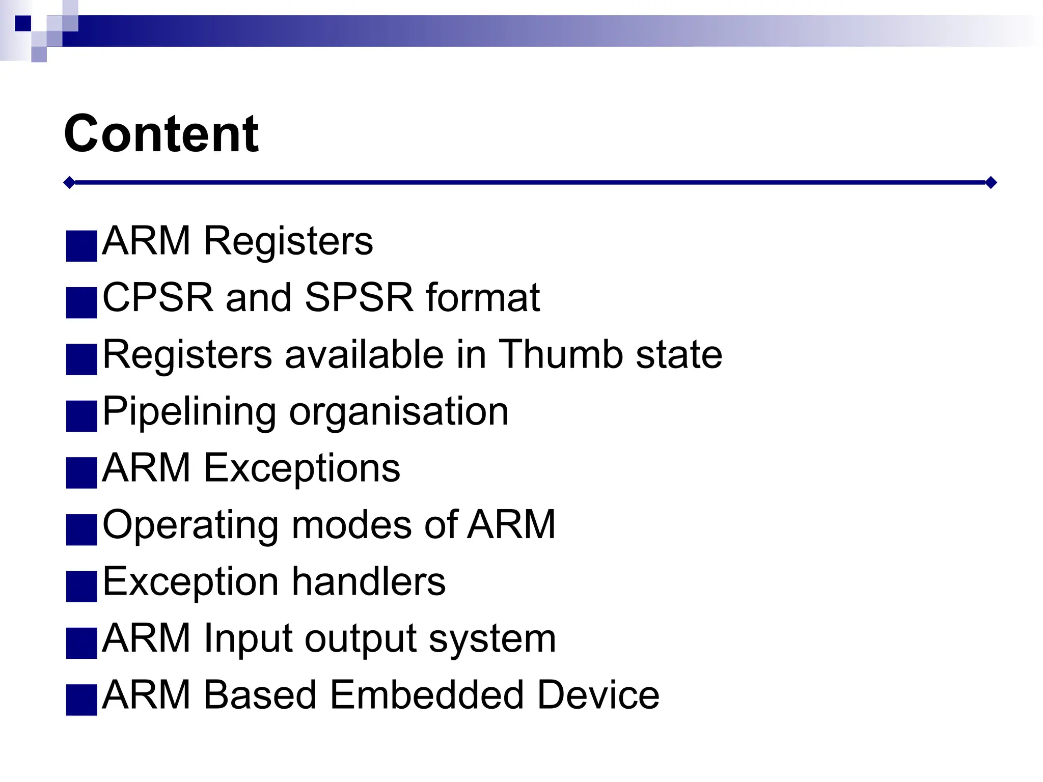
Content
■ARM Registers
■CPSR andSPSR format
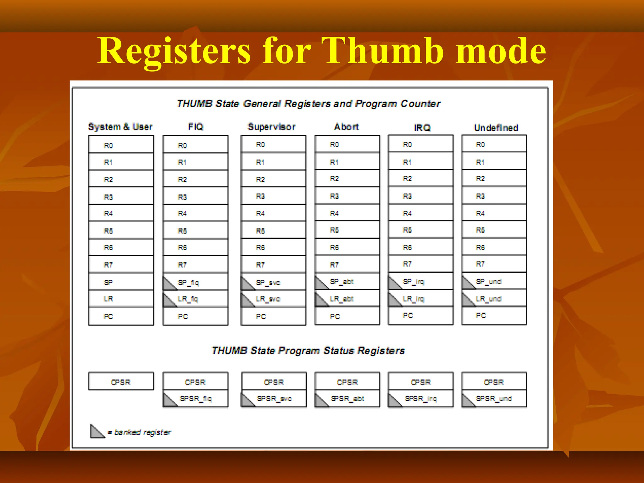
■Registers available in Thumb state
■Pipelining organisation
■ARM Exceptions
■Operating modes of ARM
■Exception handlers
■ARM Input output system
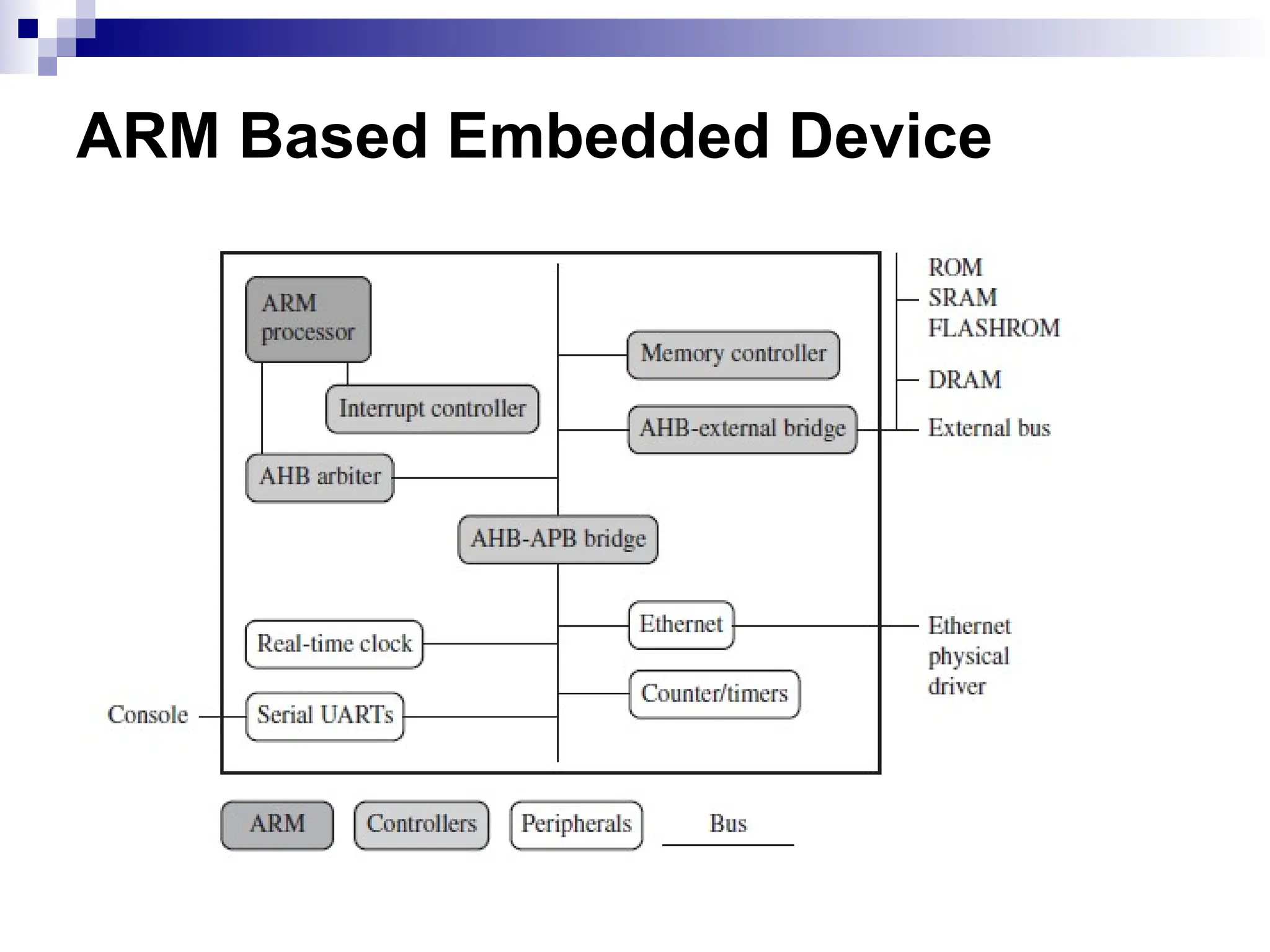
■ARM Based Embedded Device
3.
Address
Register
Register Bank
A[31:0]
PC Incrementer
Mult
Barrel
Shifter
Instruction
Decode
&
Control
ControlSignals
Data In Register
Data Out Register
ALU
D[31:0]
A
Bus
B
Bus
A LU
Bus
Register bank stores
processor state. It
has two read ports
and one write port.
Barrel shifter used to
shift or rotate one
operand by any number
of bits It is
combinational circuit
which maximize
hardware use
■Address register and
incrementer selects and
holds all memory
addresses and generates
sequential addresses
when required
4.
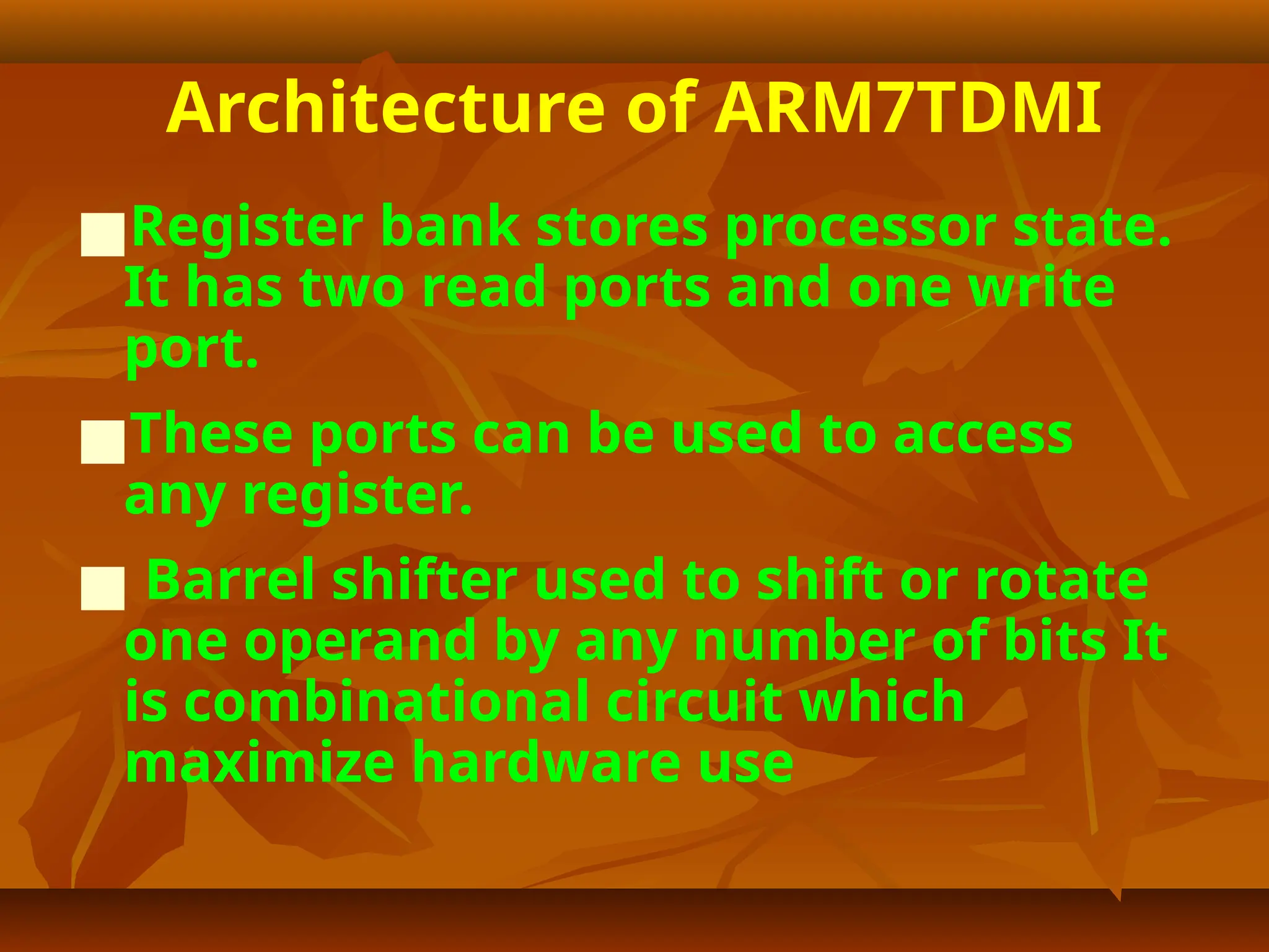
Architecture of ARM7TDMI
■Registerbank stores processor state.
It has two read ports and one write
port.
■These ports can be used to access
any register.
■ Barrel shifter used to shift or rotate
one operand by any number of bits It
is combinational circuit which
maximize hardware use
5.
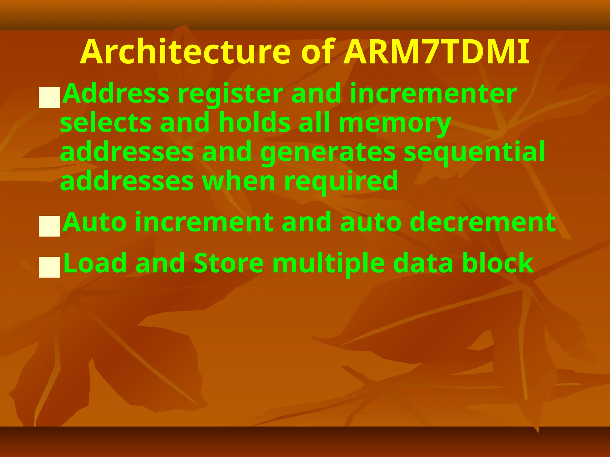
Architecture of ARM7TDMI
■Addressregister and incrementer
selects and holds all memory
addresses and generates sequential
addresses when required
■Auto increment and auto decrement
■Load and Store multiple data block
6.
Architecture of ARM7TDMI
■Insingle cycle data processing
instruction, two register operands
are accessed. Value of B bus is shifted
and combined with value on A bus in
the ALU and result is written back
into the register bank.
■Program counter value is in Address
register, from where it is fed to
incrementer. Incremented value of PC
is copied back to register R15.
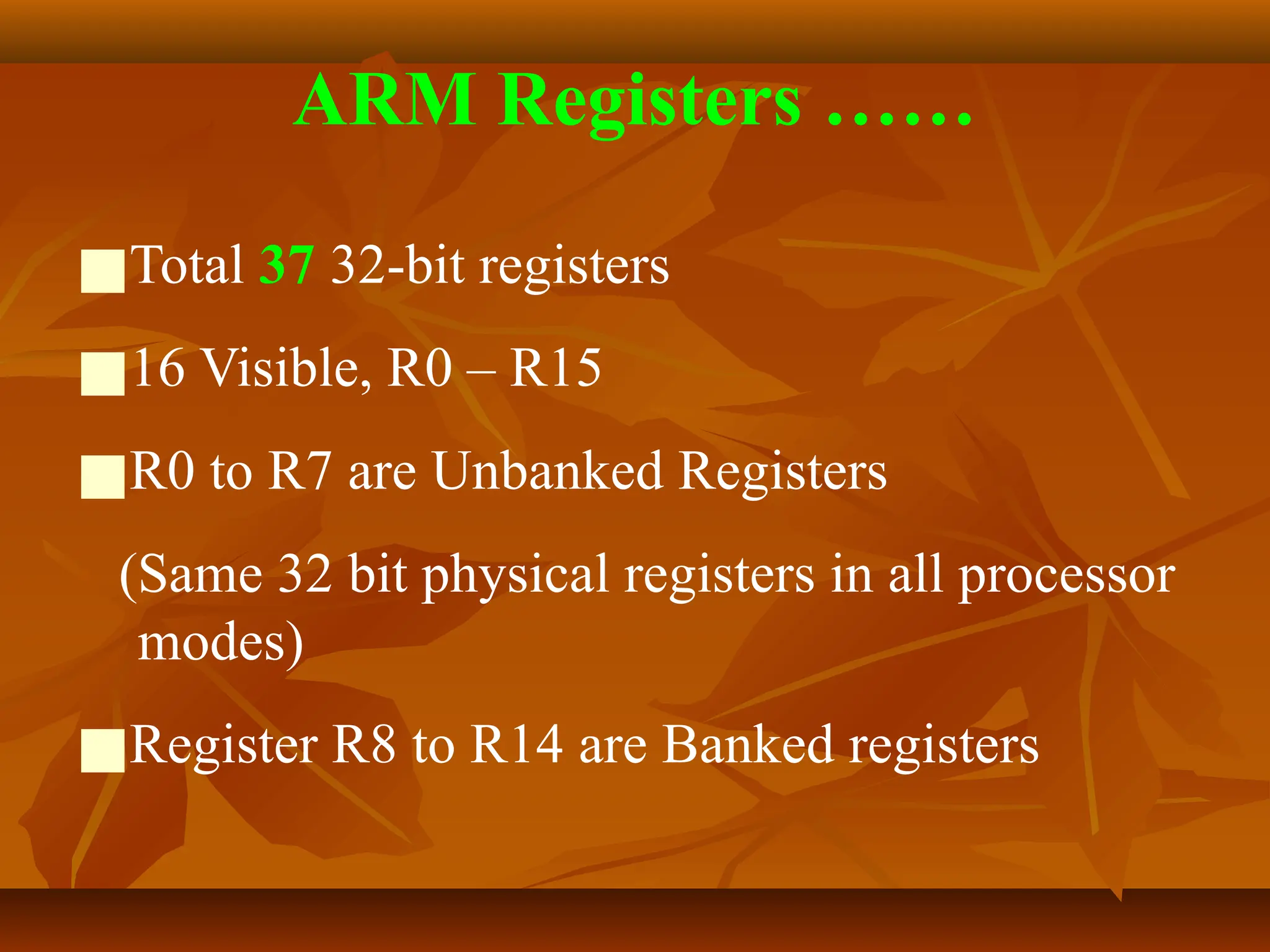
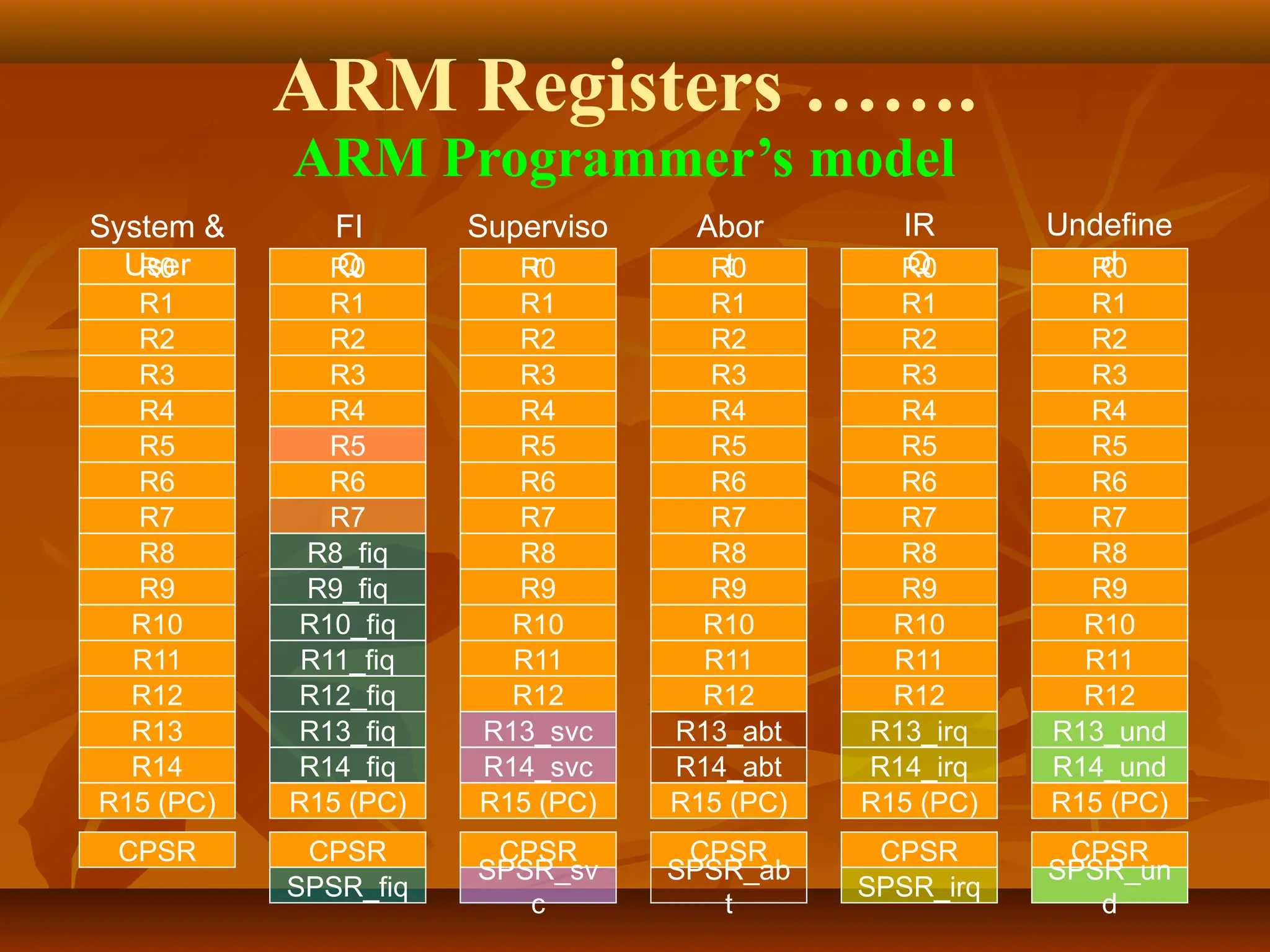
ARM Registers ……
■Total37 32-bit registers
■16 Visible, R0 – R15
■R0 to R7 are Unbanked Registers
(Same 32 bit physical registers in all processor
modes)
■Register R8 to R14 are Banked registers
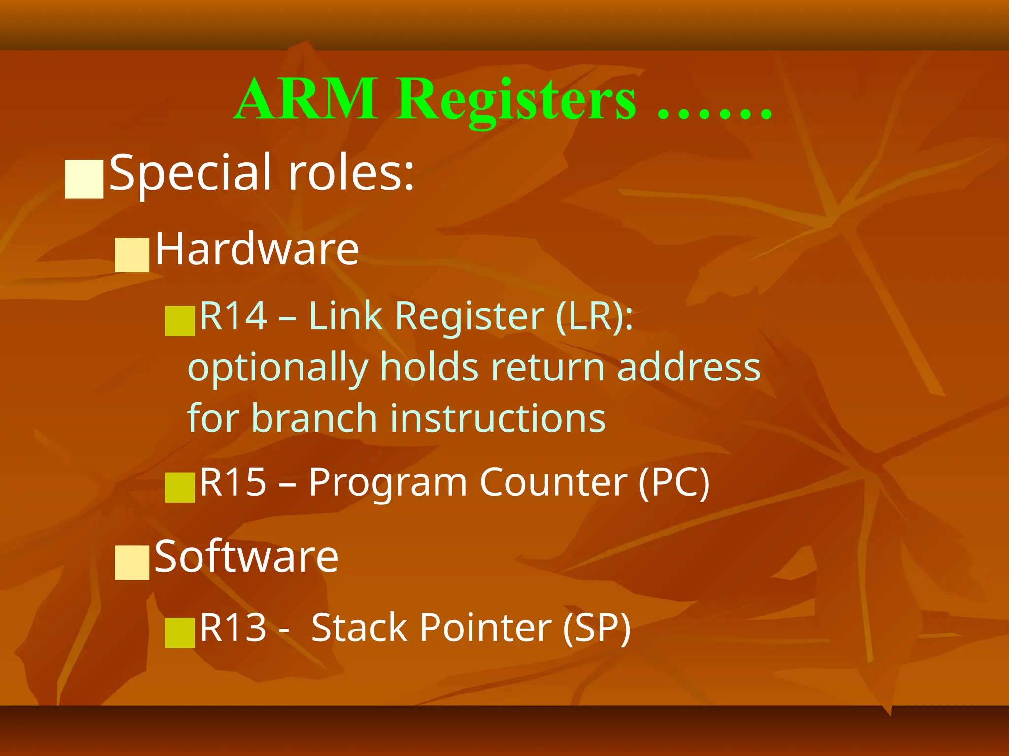
ARM Registers ……
■Specialroles:
■Hardware
■R14 – Link Register (LR):
optionally holds return address
for branch instructions
■R15 – Program Counter (PC)
■Software
■R13 - Stack Pointer (SP)
11.
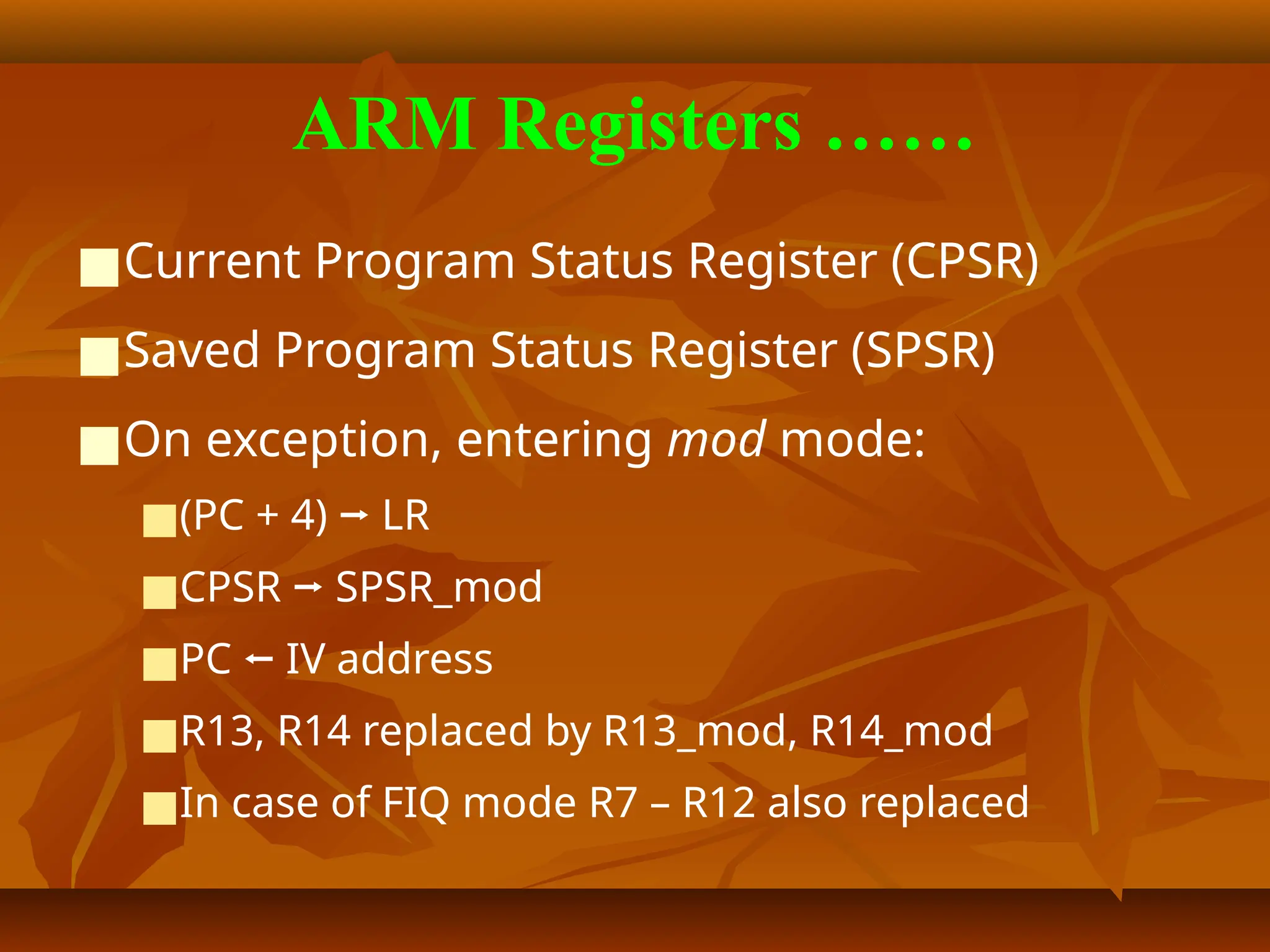
ARM Registers ……
■CurrentProgram Status Register (CPSR)
■Saved Program Status Register (SPSR)
■On exception, entering mod mode:
■(PC + 4) ⭢ LR
■CPSR ⭢ SPSR_mod
■PC ⭠ IV address
■R13, R14 replaced by R13_mod, R14_mod
■In case of FIQ mode R7 – R12 also replaced
12.
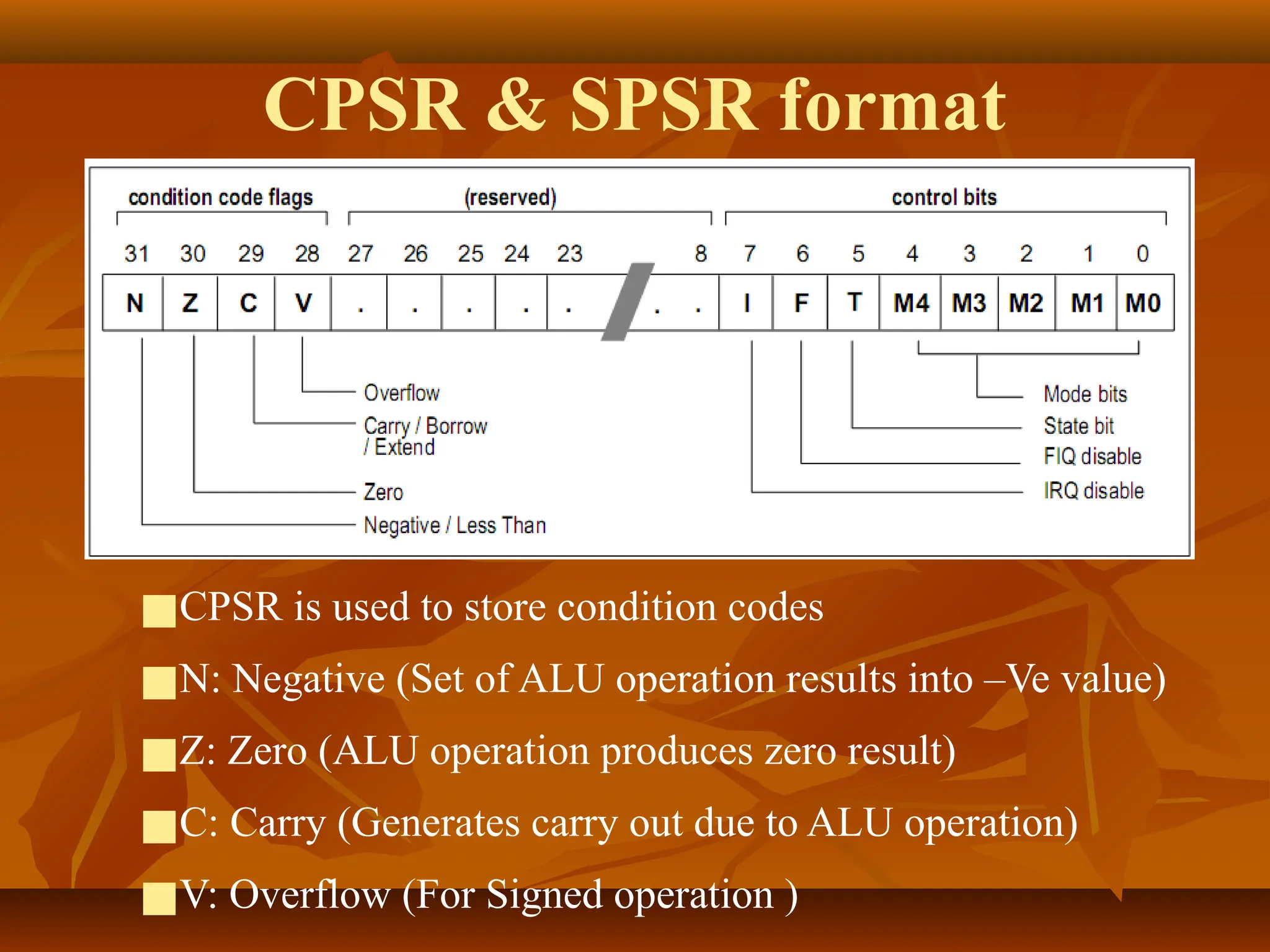
CPSR & SPSRformat
■CPSR is used to store condition codes
■N: Negative (Set of ALU operation results into –Ve value)
■Z: Zero (ALU operation produces zero result)
■C: Carry (Generates carry out due to ALU operation)
■V: Overflow (For Signed operation )
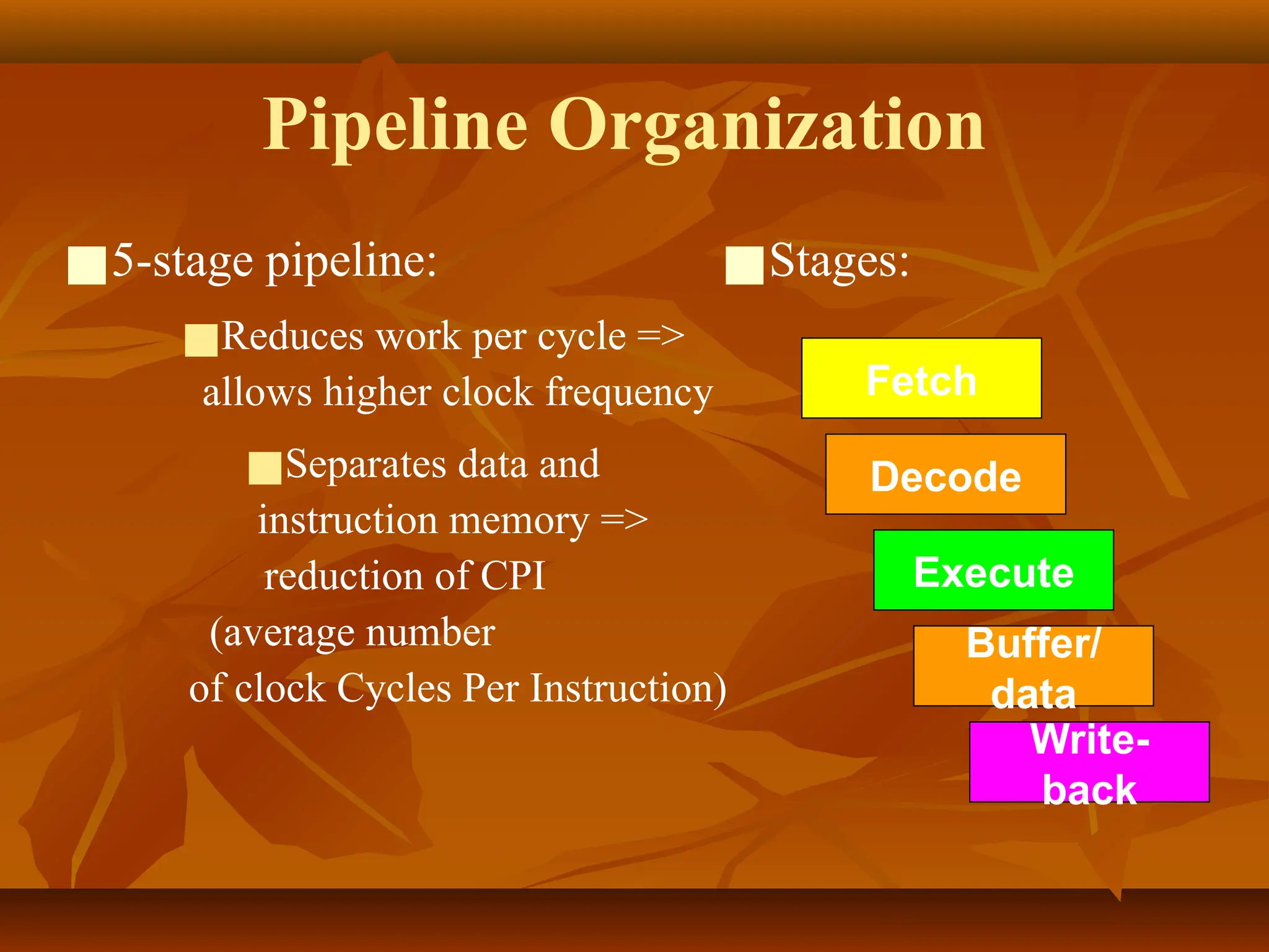
Features of ARM7TDMIarchitecture
■Uses 0.25μm and less die size and HCMOS
technology. Low die size facilitates low
voltage operation and cause low power
dissipation
■Gives high performance of 300 MIPS at die
size= 0.13μm
■Fully static operation (Since it is MOSFET
based)
16.
Features of ARM7TDMIarchitecture
■Large register set consisting 37 registers.
■Three stage pipeline
■232
addresses for 4 GByte linear address space
■32/16 bit RISC architecture (ARM v4T) which
has 32 bit ARM instruction set and 16 bit
Thumb instruction subset as extension
■32 bit RALU and high performance multiplier
17.
Features of ARM7TDMIarchitecture
■Instruction processes data with different data
types such as 8 bit, 16 bit and 32 bit.
■Two types of interrupt requests: FIQ (Fast
Interrupt Request) and IRQ (Interrupt
Request). FIQ has high priority.
■Co-processor interface available
■Extensive Debug facilities like ICE (In circuit
emulator, RT (real time) debug and on-chip
JTAG interface)
18.
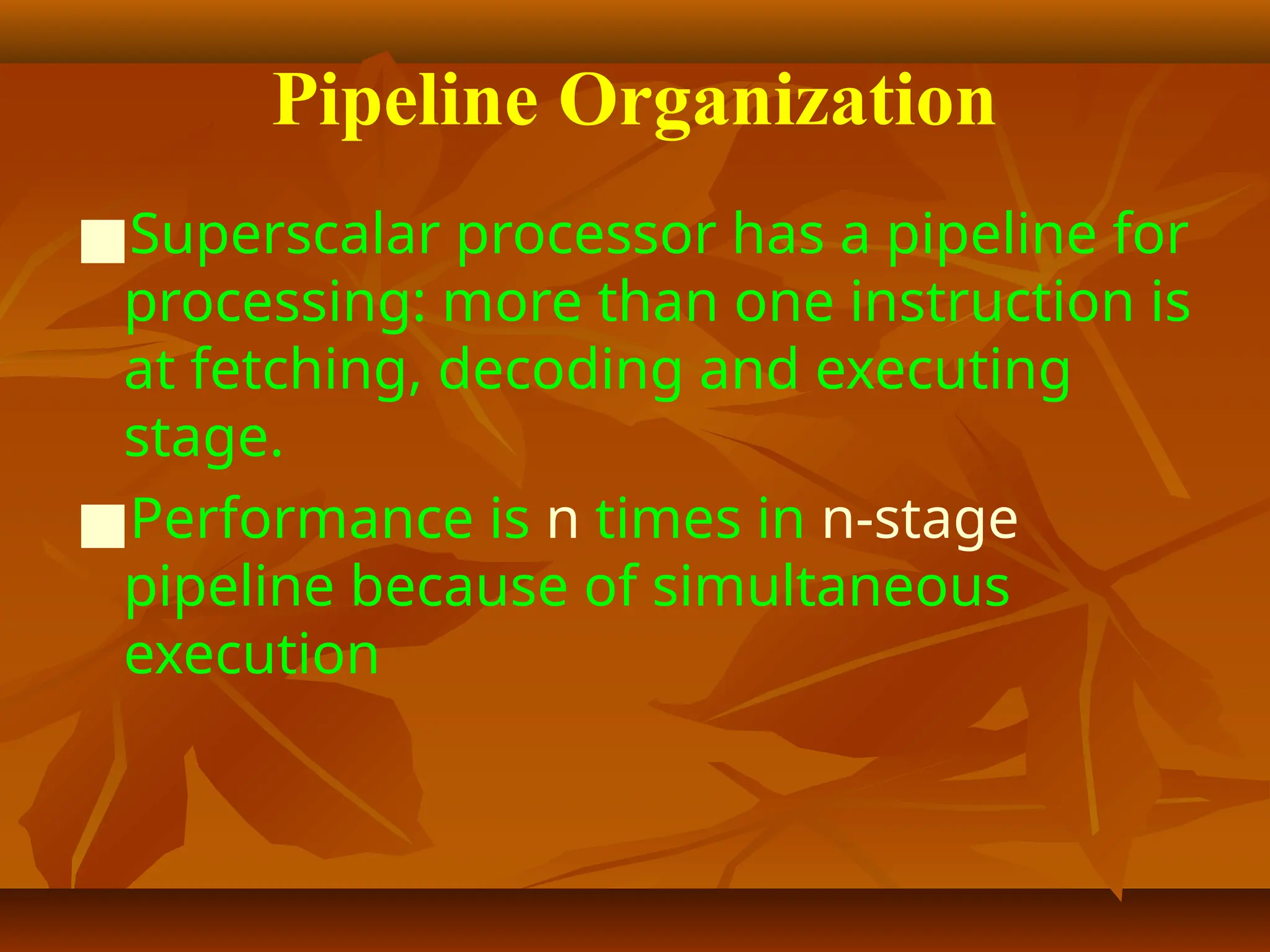
Pipeline Organization
■Superscalar processorhas a pipeline for
processing: more than one instruction is
at fetching, decoding and executing
stage.
■Performance is n times in n-stage
pipeline because of simultaneous
execution
19.
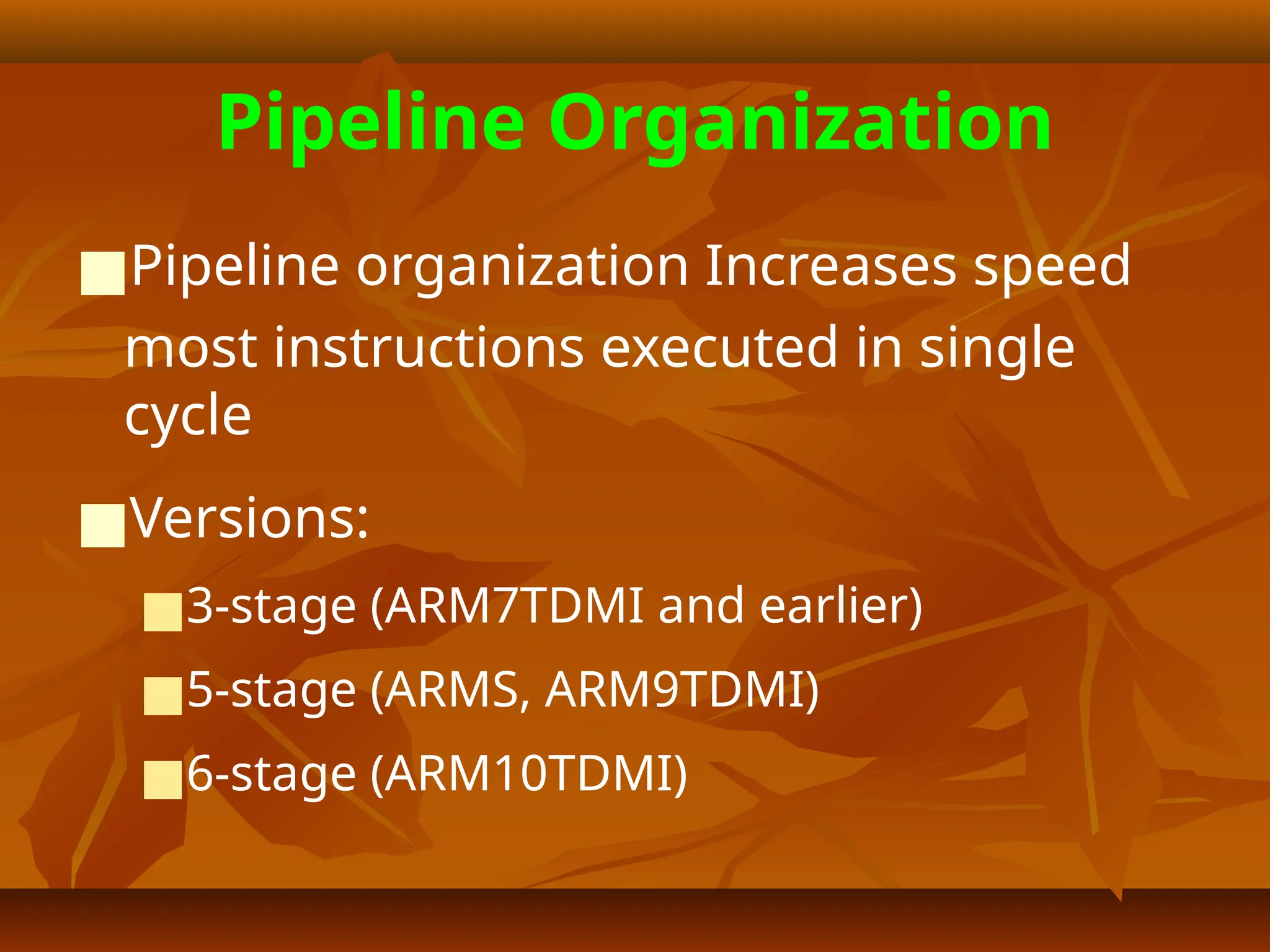
Pipeline Organization
■Pipeline organizationIncreases speed
most instructions executed in single
cycle
■Versions:
■3-stage (ARM7TDMI and earlier)
■5-stage (ARMS, ARM9TDMI)
■6-stage (ARM10TDMI)
20.
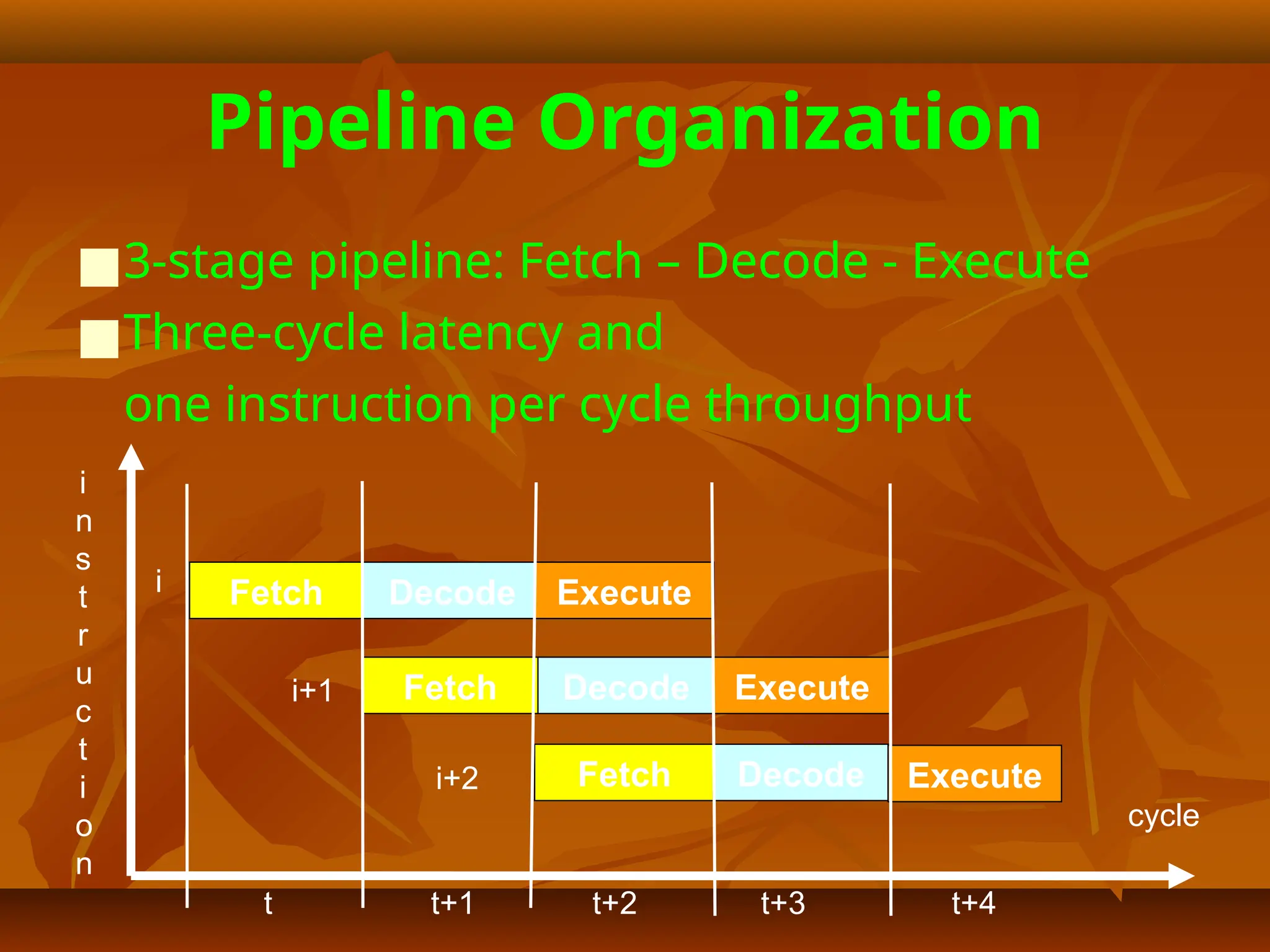
Pipeline Organization
■3-stage pipeline:Fetch – Decode - Execute
■Three-cycle latency and
one instruction per cycle throughput
cycle
Fetch Decode Execute
Fetch Decode Execute
Fetch Decode Execute
i
n
s
t
r
u
c
t
i
o
n
t t+1 t+2 t+3 t+4
i
i+1
i+2
Pipeline Organization
■Pipeline flushedand refilled on branch,
causing execution to slow down
■Special features in instruction set
eliminate small jumps in code
to obtain the best flow through pipeline
23.
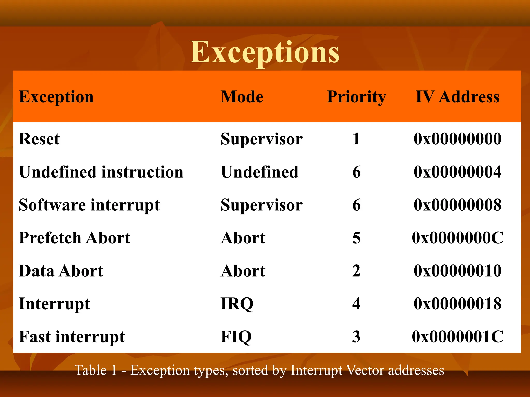
ARM Exceptions
When Exceptionoccurs ……
■Mode changes
■Saves CPSR to SPSR
■Save PC to LR
■Set CPSR to exception mode
■Set PC to address of exception handler
Operating Modes
User mode:
■Normalprogram
execution mode
■System resources
unavailable
■Mode changed
by exception only
Exception modes:
■Entered
upon exception
■Full access
to system resources
■Mode changed freely
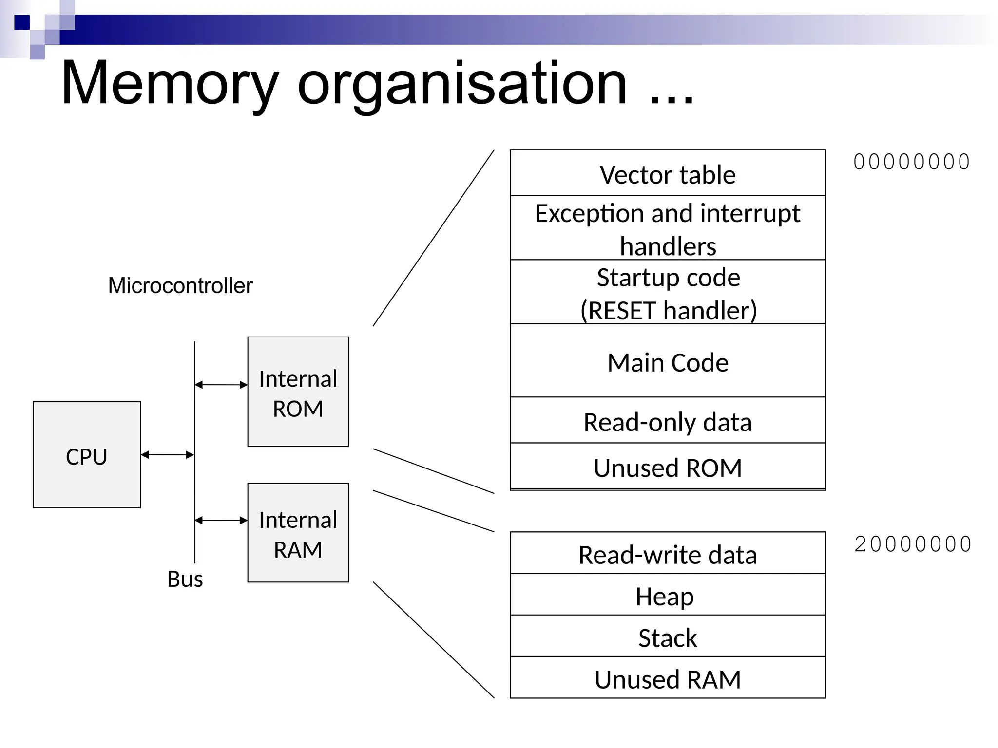
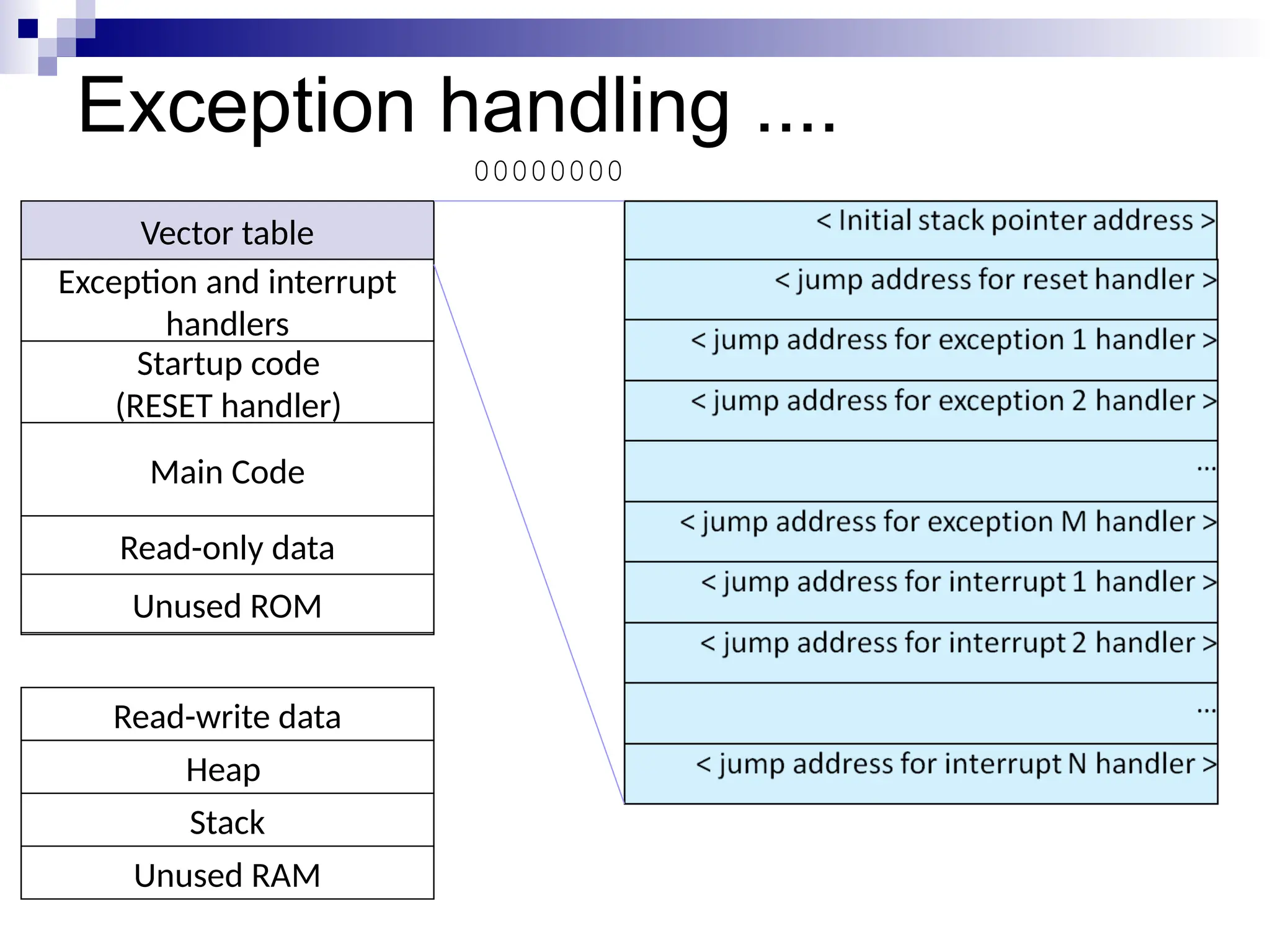
Memory organisation ...
Read-writedata
Heap
Stack
Microcontroller
Internal
ROM
Internal
RAM
CPU
Bus
Vector table
Exception and interrupt
handlers
Startup code
(RESET handler)
Read-only data
Main Code
Unused ROM
Unused RAM
00000000
20000000
28.
Exception handling ....
Read-writedata
Heap
Stack
Vector table
Exception and interrupt
handlers
Startup code
(RESET handler)
Read-only data
Main Code
Unused ROM
Unused RAM
00000000
29.
Exception routines
Vector addressfor exceptions have not enough
space to accommodate entire exception routine
so branch is taken at some another location
using branch instructions ..
■B <Address>
■MOV PC,#<Immediate Value>
■LDR PC,[PC,#<Offset Value>]
30.
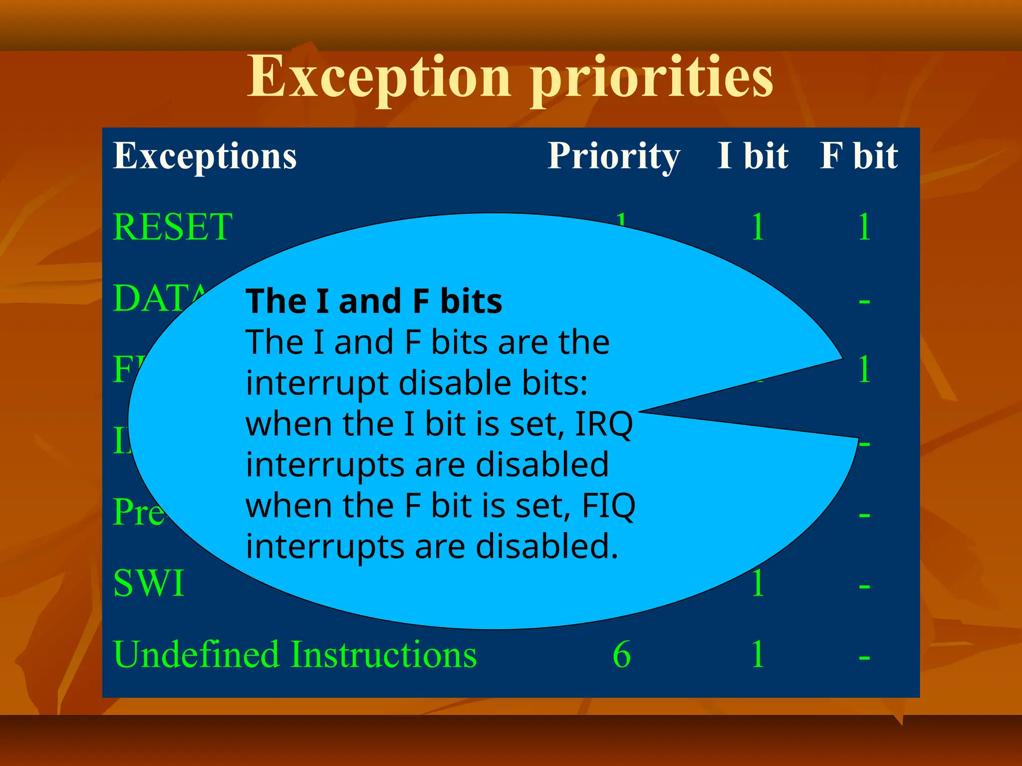
Exception priorities
Exceptions PriorityI bit F bit
RESET 1 1 1
DATAABORT 2 1 -
FIQ 3 1 1
IRQ 4 1 -
Pre-fetch abort 5 1 -
SWI 6 1 -
Undefined Instructions 6 1 -
The I and F bits
The I and F bits are the
interrupt disable bits:
when the I bit is set, IRQ
interrupts are disabled
when the F bit is set, FIQ
interrupts are disabled.
31.
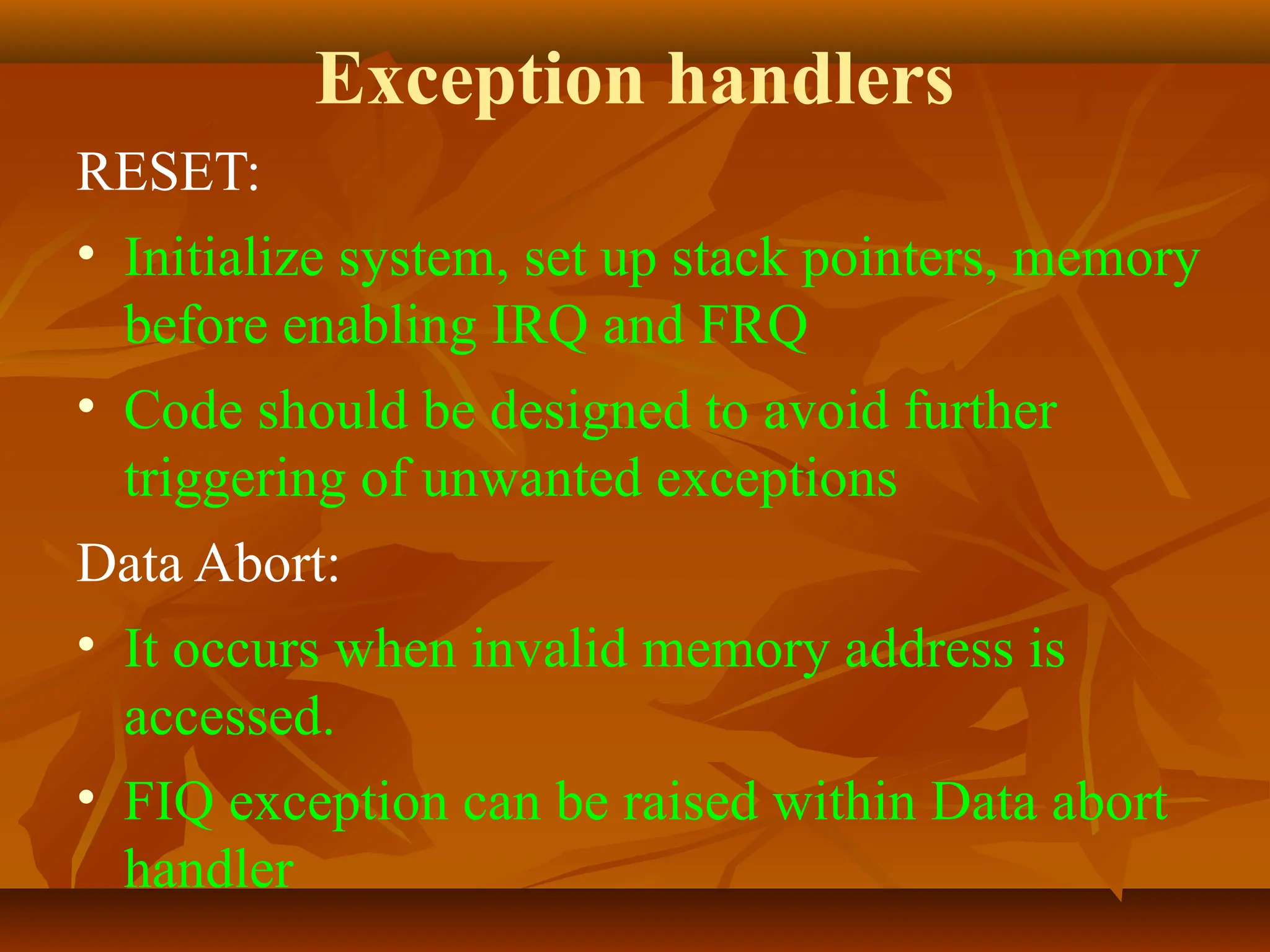
Exception handlers
RESET:
• Initializesystem, set up stack pointers, memory
before enabling IRQ and FRQ
• Code should be designed to avoid further
triggering of unwanted exceptions
Data Abort:
• It occurs when invalid memory address is
accessed.
• FIQ exception can be raised within Data abort
handler
32.
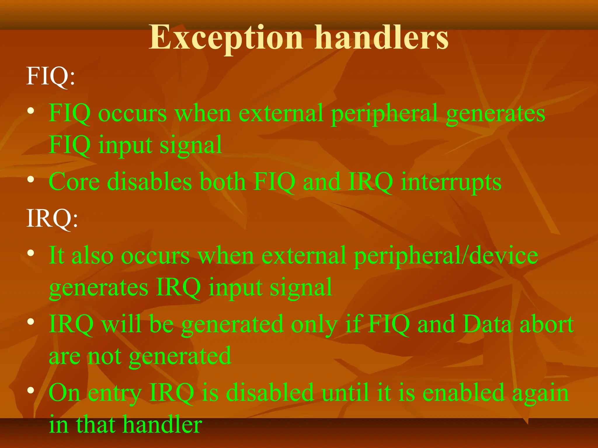
Exception handlers
FIQ:
• FIQoccurs when external peripheral generates
FIQ input signal
• Core disables both FIQ and IRQ interrupts
IRQ:
• It also occurs when external peripheral/device
generates IRQ input signal
• IRQ will be generated only if FIQ and Data abort
are not generated
• On entry IRQ is disabled until it is enabled again
in that handler
33.
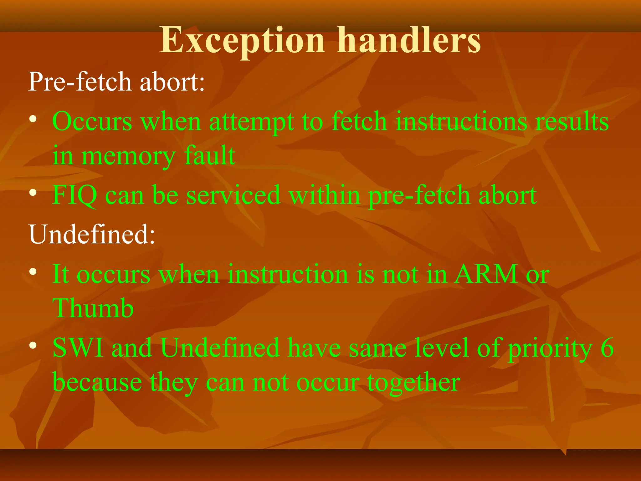
Exception handlers
Pre-fetch abort:
•Occurs when attempt to fetch instructions results
in memory fault
• FIQ can be serviced within pre-fetch abort
Undefined:
• It occurs when instruction is not in ARM or
Thumb
• SWI and Undefined have same level of priority 6
because they can not occur together
34.
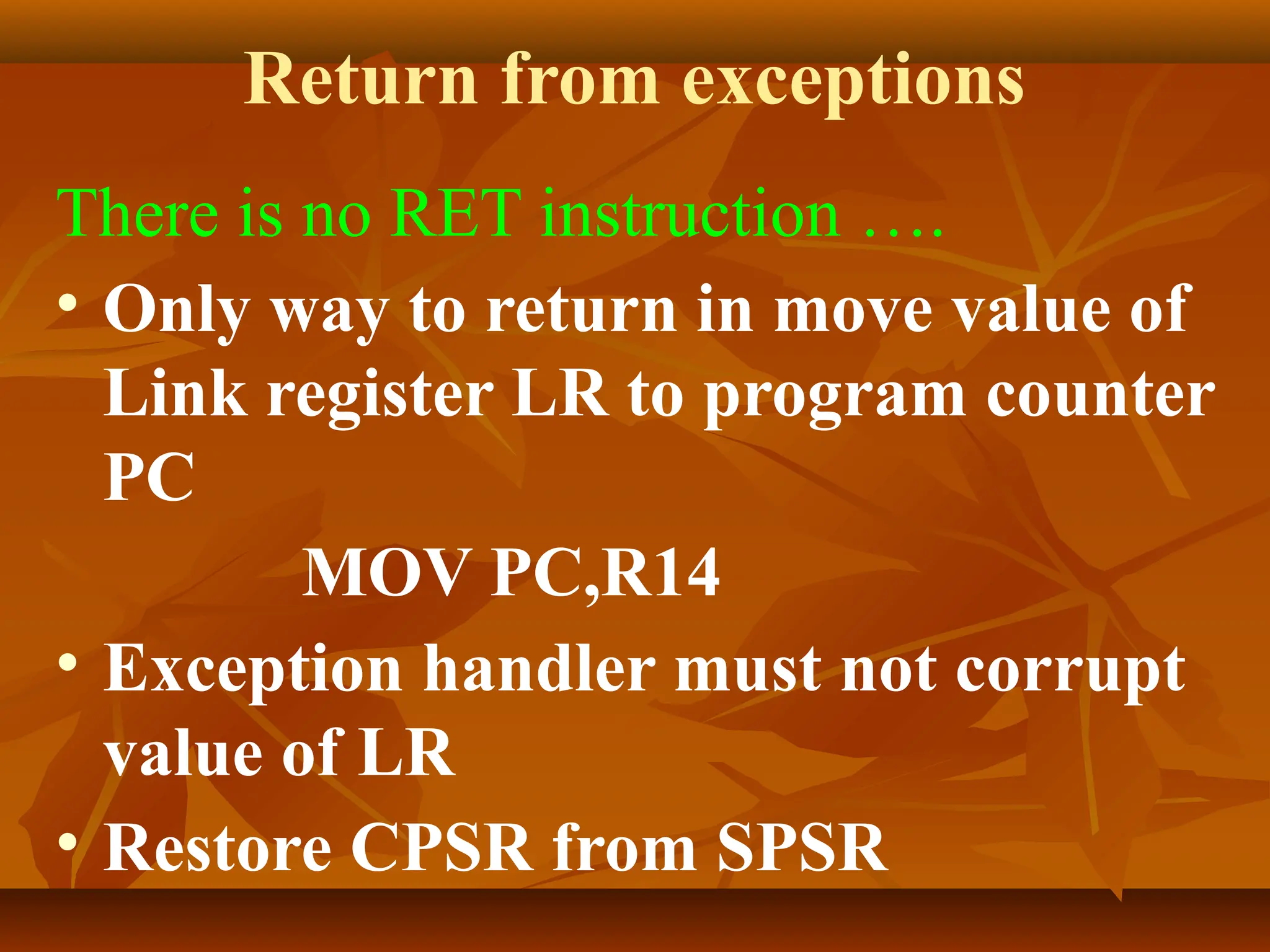
Return from exceptions
Thereis no RET instruction ….
• Only way to return in move value of
Link register LR to program counter
PC
MOV PC,R14
• Exception handler must not corrupt
value of LR
• Restore CPSR from SPSR
35.
Interrupt assignment
• Interruptcontroller can be used to
connect general purpose interrupts to
FIQ or IRQ
• FIQ is usually reserved for interrupts
which requires fast response time
• IRQ assigned to general purpose
interrupts like periodic timer
interrupts for context switching of
processes
36.
Interrupt Latency
• Hardwareand software latency
• Hardware (Use more registers)
• Software (Use nested interrupt
handler which allows interrupt inside
interrupt)
• Stack organization is needed for
reducing interrupt latency using
software. Average latency of high
priority interrupt reduces
37.
Interrupt Latency
• Stacksize requirement is more for
nested interrupt handler
• Size of stack can be designed by
looking at embedded system
application such as what are the
sources of interrupts, how much
interrupt latency can be tolerated
etc..
38.
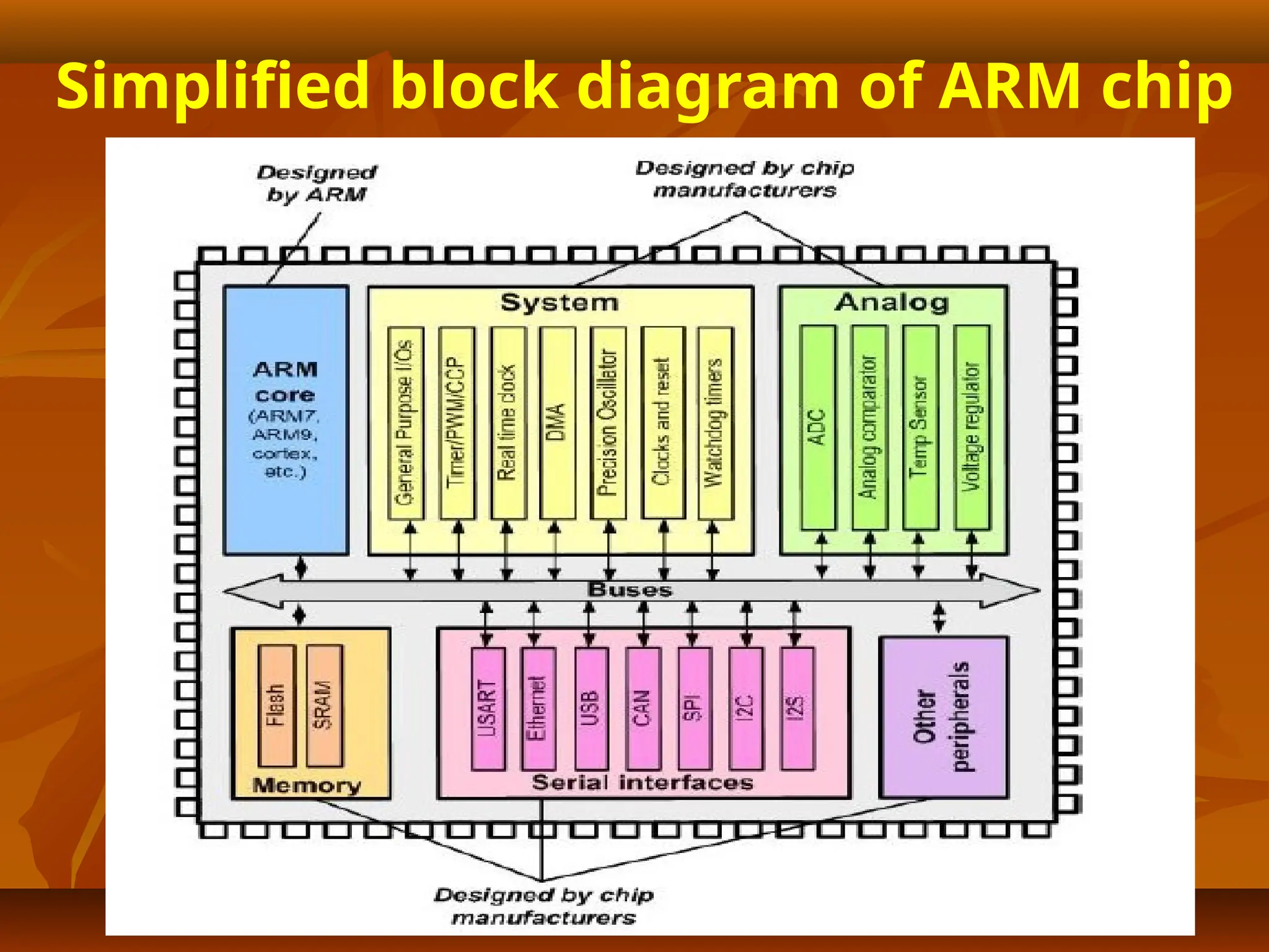
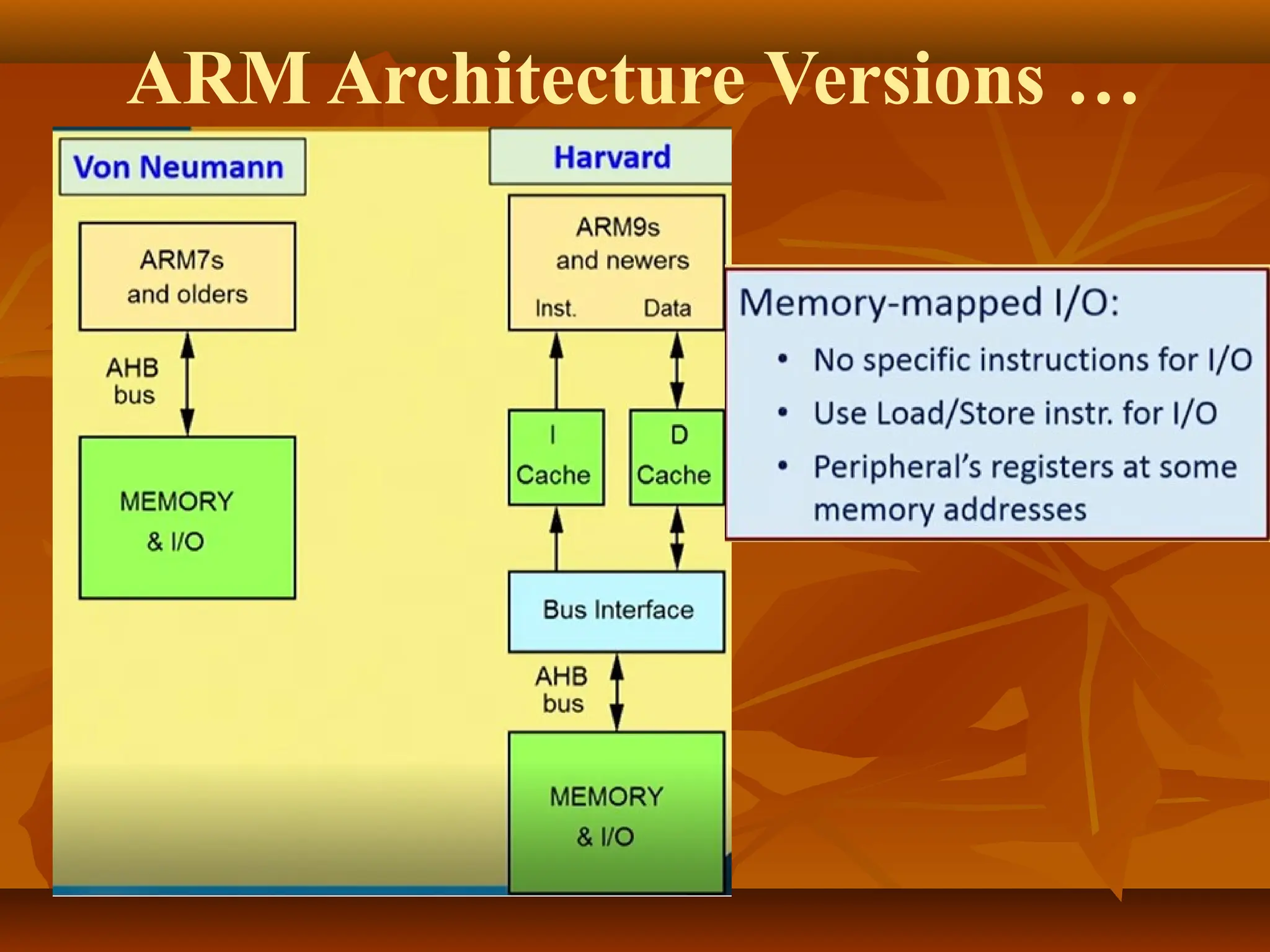
ARM Input-Output System
•ARM I/O system uses memory
mapped I/O
• No separate address range for I/O
devices
• Interrupt support is: IRQ & FIQ
• DMA support: large bandwidth and
data transfer

![Address
Register
Register Bank
A[31:0]
PC Incrementer
Mult
Barrel
Shifter
Instruction
Decode
&
Control
Control Signals
Data In Register
Data Out Register
ALU
D[31:0]
A
Bus
B
Bus
A LU
Bus
Register bank stores
processor state. It
has two read ports
and one write port.
Barrel shifter used to
shift or rotate one
operand by any number
of bits It is
combinational circuit
which maximize
hardware use
■Address register and
incrementer selects and
holds all memory
addresses and generates
sequential addresses
when required](https://image.slidesharecdn.com/topic2armarchitectureandprogrammersmodel-250328051119-af23b066/75/Topic-2-ARM-Architecture-and-Programmer-s-Model-pptx-3-2048.jpg)

![Exception routines
Vector address for exceptions have not enough
space to accommodate entire exception routine
so branch is taken at some another location
using branch instructions ..
■B <Address>
■MOV PC,#<Immediate Value>
■LDR PC,[PC,#<Offset Value>]](https://image.slidesharecdn.com/topic2armarchitectureandprogrammersmodel-250328051119-af23b066/75/Topic-2-ARM-Architecture-and-Programmer-s-Model-pptx-29-2048.jpg)
![References:
[1] Arm System Developer’s Guide, Designing and
Optimizing Software, Andrew N. Sloss, Dominic
Symes, Chris Wwight, Elsevier
[2] www.arm.com](https://image.slidesharecdn.com/topic2armarchitectureandprogrammersmodel-250328051119-af23b066/75/Topic-2-ARM-Architecture-and-Programmer-s-Model-pptx-41-2048.jpg)