The document describes the ARM instruction set architecture. It discusses the processor modes, registers, program counter, condition flags, and instruction formats. The ARM uses a pipeline and conditional execution to improve performance. Most instructions are 32-bits and word-aligned. The program counter points to the next instruction to fetch. Branch instructions calculate a signed offset that is added to the program counter.


![The ARM Instruction Set - ARM University Program - V1.0 8
The Program Status Registers
(CPSR and SPSRs)
Copies of the ALU status flags (latched if the
instruction has the "S" bit set).
N = Negative result from ALU flag.
Z = Zero result from ALU flag.
C = ALU operation Carried out
V = ALU operation oVerflowed
* Interrupt Disable bits.
I = 1, disables the IRQ.
F = 1, disables the FIQ.
* T Bit (Architecture v4T only)
T = 0, Processor in ARM state
T = 1, Processor in Thumb state
* Condition Code Flags
Mode
N Z C V
28
31 8 4 0
I F T
* Mode Bits
M[4:0] define the processor mode.](https://image.slidesharecdn.com/esd05arminstructions-240113074719-e7e68ca6/85/ESD_05_ARM_Instructions-set-for-preparation-8-320.jpg)

![The ARM Instruction Set - ARM University Program - V1.0 10
* When the processor is executing in ARM state:
• All instructions are 32 bits in length
• All instructions must be word aligned
• Therefore the PC value is stored in bits [31:2] with bits [1:0] equal to
zero (as instruction cannot be halfword or byte aligned).
* R14 is used as the subroutine link register (LR) and stores the return
address when Branch with Link operations are performed,
calculated from the PC.
* Thus to return from a linked branch
• MOV r15,r14
or
• MOV pc,lr
The Program Counter (R15)](https://image.slidesharecdn.com/esd05arminstructions-240113074719-e7e68ca6/85/ESD_05_ARM_Instructions-set-for-preparation-10-320.jpg)


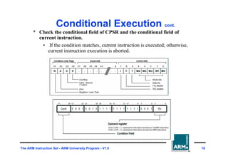
![The ARM Instruction Set - ARM University Program - V1.0 19
Conditional Execution cont.
* Reducing the number of branches
• MOVS r0, r1, LSR #1 ; C(flag) := r1[0]
• MOVCC r0, #10 ; if C=0, then r0 := 10
• MOVCS r0, #11 ; if C=1, then r0 := 11
• MOVS r0, r4 ; if r4==0 then r0 := 0
• MOVNE r0, #1 ; else r0 := 1](https://image.slidesharecdn.com/esd05arminstructions-240113074719-e7e68ca6/85/ESD_05_ARM_Instructions-set-for-preparation-19-320.jpg)


![The ARM Instruction Set - ARM University Program - V1.0 26
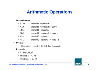
Logical Operations
* Operations are:
• AND operand1 AND operand2
• EOR operand1 EOR operand2
• ORR operand1 OR operand2
• BIC operand1 AND NOT operand2 [ie bit clear]
* Syntax:
• <Operation>{<cond>}{S} Rd, Rn, Operand2
* Examples:
• AND r0, r1, r2
• BICEQ r2, r3, #7
• EORS r1,r3,r0](https://image.slidesharecdn.com/esd05arminstructions-240113074719-e7e68ca6/85/ESD_05_ARM_Instructions-set-for-preparation-26-320.jpg)


![The ARM Instruction Set - ARM University Program - V1.0 34
The cross-bar switch barrel
shifter principle
in[0]
in[1]
in[2]
in[3]
out[0] out[1] out[2] out[3]
no shift
right 1
right 2
right 3
left 1
left 2
left 3](https://image.slidesharecdn.com/esd05arminstructions-240113074719-e7e68ca6/85/ESD_05_ARM_Instructions-set-for-preparation-34-320.jpg)


![The ARM Instruction Set - ARM University Program - V1.0 40
Second Operand :
Immediate Value (2)
* This gives us:
• 0 - 255 [0 - 0xff]
• 256,260,264,..,1020 [0x100-0x3fc, step 4, 0x40-0xff ror 30]
• 1024,1040,1056,..,4080 [0x400-0xff0, step 16, 0x40-0xff ror 28]
• 4096,4160, 4224,..,16320 [0x1000-0x3fc0, step 64, 0x40-0xff ror 26]
* These can be loaded using, for example:
• MOV r0, #0x40, 26 ; => MOV r0, #0x1000 (ie 4096)
* To make this easier, the assembler will convert to this form for us if
simply given the required constant:
• MOV r0, #4096 ; => MOV r0, #0x1000 (ie 0x40 ror 26)
* The bitwise complements can also be formed using MVN:
• MOV r0, #0xFFFFFFFF ; assembles to MVN r0, #0
* If the required constant cannot be generated, an error will
be reported.](https://image.slidesharecdn.com/esd05arminstructions-240113074719-e7e68ca6/85/ESD_05_ARM_Instructions-set-for-preparation-40-320.jpg)
![The ARM Instruction Set - ARM University Program - V1.0 41
Loading full 32 bit constants
* Although the MOV/MVN mechansim will load a large range of constants
into a register, sometimes this mechansim will not generate the required
constant.
* Therefore, the assembler also provides a method which will load ANY
ANY 32
bit constant:
• LDR rd,=numeric constant
* If the constant can be constructed using either a MOV or MVN then this
will be the instruction actually generated.
* Otherwise, the assembler will produce an LDR instruction with a PC-
relative address to read the constant from a literal pool.
• LDR r0,=0x42 ; generates MOV r0,#0x42
• LDR r0,=0x55555555 ; generate LDR r0,[pc, offset to lit pool]
* As this mechanism will always generate the best instruction for a given
case, it is the recommended way of loading constants.](https://image.slidesharecdn.com/esd05arminstructions-240113074719-e7e68ca6/85/ESD_05_ARM_Instructions-set-for-preparation-41-320.jpg)


![The ARM Instruction Set - ARM University Program - V1.0 47
Load and Store Word or Byte:
Base Register
* The memory location to be accessed is held in a base register
• STR r0, [r1] ; Store contents of r0 to location pointed to
; by contents of r1.
• LDR r2, [r1] ; Load r2 with contents of memory location
; pointed to by contents of r1.
r1
0x200
Base
Register
Memory
0x5
0x200
r0
0x5
Source
Register
for STR
r2
0x5
Destination
Register
for LDR](https://image.slidesharecdn.com/esd05arminstructions-240113074719-e7e68ca6/85/ESD_05_ARM_Instructions-set-for-preparation-47-320.jpg)

![The ARM Instruction Set - ARM University Program - V1.0 49
Load and Store Word or Byte:
Pre-indexed Addressing
* Example: STR r0, [r1,#12]
* To store to location 0x1f4 instead use: STR r0, [r1,#-12]
* To auto-increment base pointer to 0x20c use: STR r0, [r1, #12]!
* If r2 contains 3, access 0x20c by multiplying this by 4:
• STR r0, [r1, r2, LSL #2]
r1
0x200
Base
Register
Memory
0x5
0x200
r0
0x5
Source
Register
for STR
Offset
12 0x20c](https://image.slidesharecdn.com/esd05arminstructions-240113074719-e7e68ca6/85/ESD_05_ARM_Instructions-set-for-preparation-49-320.jpg)
![The ARM Instruction Set - ARM University Program - V1.0 50
Load and Store Word or Byte:
Post-indexed Addressing
* Example: STR r0, [r1], #12
* To auto-increment the base register to location 0x1f4 instead use:
• STR r0, [r1], #-12
* If r2 contains 3, auto-incremenet base register to 0x20c by multiplying
this by 4:
• STR r0, [r1], r2, LSL #2
r1
0x200
Original
Base
Register
Memory
0x5
0x200
r0
0x5
Source
Register
for STR
Offset
12 0x20c
r1
0x20c
Updated
Base
Register](https://image.slidesharecdn.com/esd05arminstructions-240113074719-e7e68ca6/85/ESD_05_ARM_Instructions-set-for-preparation-50-320.jpg)

![The ARM Instruction Set - ARM University Program - V1.0 52
Example Usage of
Addressing Modes
* Imagine an array, the first element of which is pointed to by the contents
of r0.
* If we want to access a particular element,
then we can use pre-indexed addressing:
• r1 is element we want.
• LDR r2, [r0, r1, LSL #2]
* If we want to step through every
element of the array, for instance
to produce sum of elements in the
array, then we can use post-indexed addressing within a loop:
• r1 is address of current element (initially equal to r0).
• LDR r2, [r1], #4
Use a further register to store the address of final element,
so that the loop can be correctly terminated.
0
1
2
3
element
0
4
8
12
Memory
Offset
r0
Pointer to
start of array](https://image.slidesharecdn.com/esd05arminstructions-240113074719-e7e68ca6/85/ESD_05_ARM_Instructions-set-for-preparation-52-320.jpg)

![The ARM Instruction Set - ARM University Program - V1.0 54
Quiz #4 - Sample Solution
ADD r0, r0, r1, LSL#2 ; Set r0 to address of element x
ADD r2, r0, r2, LSL#2 ; Set r2 to address of element n+1
MOV r1, #0 ; Initialise counter
loop
LDR r3, [r0], #4 ; Access element and move to next
ADD r1, r1, r3 ; Add contents to counter
CMP r0, r2 ; Have we reached element x+n?
BLT loop ; If not - repeat for
; next element
; on exit sum contained in r1](https://image.slidesharecdn.com/esd05arminstructions-240113074719-e7e68ca6/85/ESD_05_ARM_Instructions-set-for-preparation-54-320.jpg)


![The ARM Instruction Set - ARM University Program - V1.0 65
* Atomic operation of a memory read followed by a memory write
which moves byte or word quantities between registers and
memory.
* Syntax:
• SWP{<cond>}{B} Rd, Rm, [Rn]
* Thus to implement an actual swap of contents make Rd = Rm.
* The compiler cannot produce this instruction.
Swap and Swap Byte
Instructions
Rm Rd
Rn
3
2
1
temp
Memory](https://image.slidesharecdn.com/esd05arminstructions-240113074719-e7e68ca6/85/ESD_05_ARM_Instructions-set-for-preparation-65-320.jpg)