Download to read offline

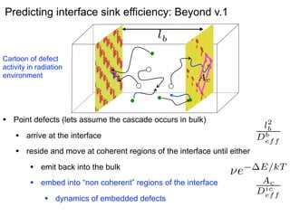
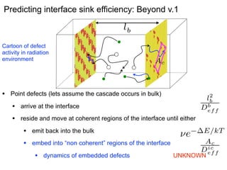
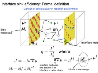

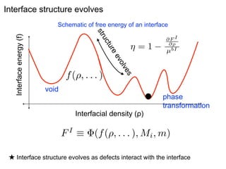
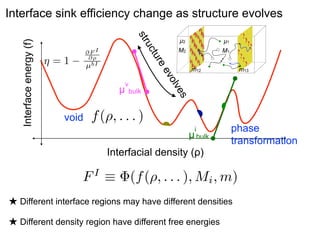

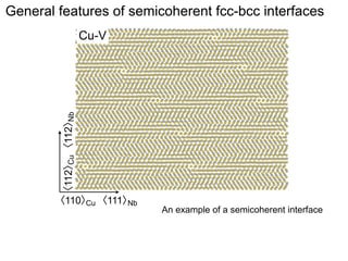
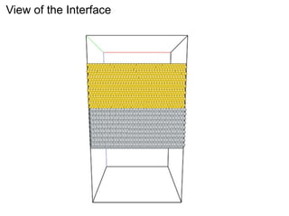
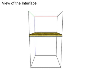
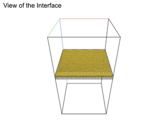
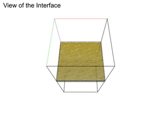
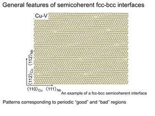
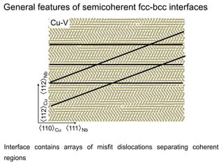
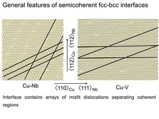
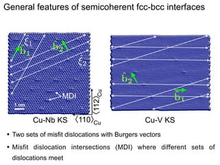
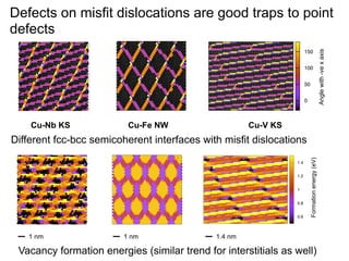
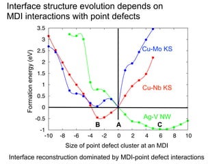
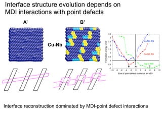
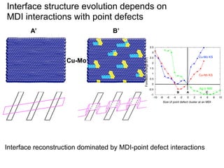
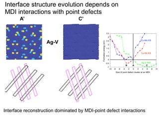

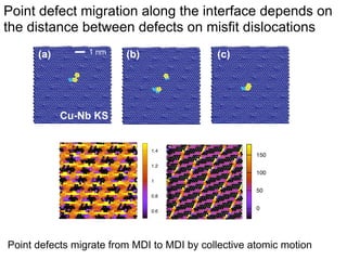
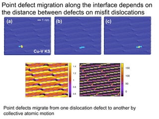
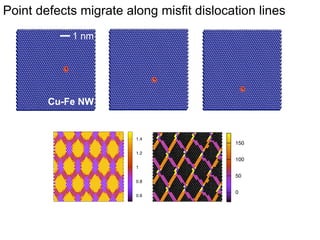
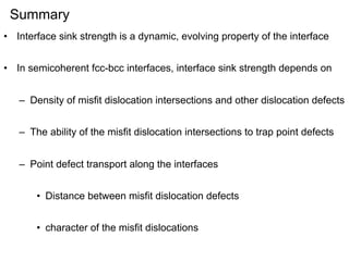

The document discusses factors that govern the sink strength of semicoherent fcc-bcc metal interfaces. It notes that such interfaces contain arrays of misfit dislocations that separate coherent regions. Misfit dislocation intersections act as good traps for point defects, and the interaction of point defects with these intersections can drive interface reconstruction and evolution over time. The goal is to understand and predict how the interface structure and sink efficiency change as defects are absorbed using calculations of interface free energy and point defect mobilities along the interface.


