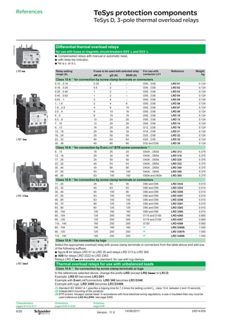
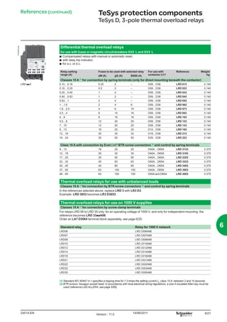
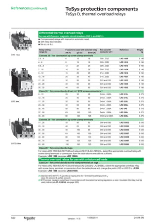
1. 6/20
PF526200.eps
Differential thermal overload relays
for use with fuses or magnetic circuit-breakers GV2 L and GV3 L
bb Compensated relays with manual or automatic reset,
bb with relay trip indicator,
bb for a.c. or d.c.
LRD pp Relay setting
range (A)
Fuses to be used with selected relay For use with
contactor LC1
Reference Weight
kgaM (A) gG (A) BS88 (A)
Class 10 A (1)
for connection by screw clamp terminals or connectors
0.10…0.16 0.25 2 – D09…D38 LRD 01 0.124
0.16…0.25 0.5 2 – D09…D38 LRD 02 0.124
0.25…0.40 1 2 – D09…D38 LRD 03 0.124
PF526201.eps
0.40…0.63 1 2 – D09…D38 LRD 04 0.124
0.63…1 2 4 – D09…D38 LRD 05 0.124
1…1.6 2 4 6 D09…D38 LRD 06 0.124
1.6…2.5 4 6 10 D09…D38 LRD 07 0.124
2.5…4 6 10 16 D09…D38 LRD 08 0.124
4…6 8 16 16 D09…D38 LRD 10 0.124
5.5…8 12 20 20 D09…D38 LRD 12 0.124
7…10 12 20 20 D09…D38 LRD 14 0.124
9…13 16 25 25 D12…D38 LRD 16 0.124
12…18 20 35 32 D18…D38 LRD 21 0.124
16…24 25 50 50 D25…D38 LRD 22 0.124
LRD 3pp 23…32 40 63 63 D25…D38 LRD 32 0.124
30…38 40 80 80 D32 and D38 LRD 35 0.124
Class 10 A (1)
for connection by EverLink®
BTR screw connectors (3)
9…13 16 25 25 D40A…D65A LRD 313 0.375
12…18 20 32 35 D40A…D65A LRD 318 0.375
17…25 25 50 50 D40A…D65A LRD 325 0.375
PF526202.eps
23…32 40 63 63 D40A…D65A LRD 332 0.375
30…40 40 80 80 D40A…D65A LRD 340 0.375
37…50 63 100 100 D40A…D65A LRD 350 0.375
48…65 63 100 100 D50A and D65A LRD 365 0.375
Class 10 A (1)
for connection by screw clamp terminals or connectors
17…25 25 50 50 D80 and D95 LRD 3322 0.510
23…32 40 63 63 D80 and D95 LRD 3353 0.510
30…40 40 100 80 D80 and D95 LRD 3355 0.510
LRD 33pp 37…50 63 100 100 D80 and D95 LRD 3357 0.510
48…65 63 100 100 D80 and D95 LRD 3359 0.510
55…70 80 125 125 D80 and D95 LRD 3361 0.510
63…80 80 125 125 D80 and D95 LRD 3363 0.510
80…104 100 160 160 D80 and D95 LRD 3365 0.510
80…104 125 200 160 D115 and D150 LRD 4365 0.900
PF526203.eps
95…120 125 200 200 D115 and D150 LRD 4367 0.900
110…140 160 250 200 D150 LRD 4369 0.900
80…104 100 160 160 (2) LRD 33656 1.000
95…120 125 200 200 (2) LRD 33676 1.000
110…140 160 250 200 (2) LRD 33696 1.000
Class 10 A (1)
for connection by lugs
Select the appropriate overload relay with screw clamp terminals or connectors from the table above and add one
of the following suffixes:
bb figure 6 for relays LRD 01 to LRD 35 and relays LRD 313 to LRD 365.
bb A66 for relays LRD 3322 to LRD 3363.
Relays LRD 43pp are suitable, as standard, for use with lug-clamps.
LRD 3pp6 Thermal overload relays for use with unbalanced loads
Class 10 A (1)
for connection by screw clamp terminals or lugs
In the references selected above, change the prefix LRD (except LRD 4ppp) to LR3 D.
Example: LRD 01 becomes LR3 D01.
Example with EverLink®
connectors: LRD 340 becomes LR3 D340.
Example with lugs: LRD 3406 becomes LR3 D3406.
(1) Standard IEC 60947-4-1 specifies a tripping time for 7.2 times the setting current IR
: class 10 A: between 2 and 10 seconds.
(2) Independent mounting of the contactor.
(3) BTR screws: hexagon socket head. In accordance with local electrical wiring regulations, a size 4 insulated Allen key must be
used (reference LAD ALLEN4, see page 5/85).
References
Characteristics:
pages 6/14 to 6/17
Dimensions:
pages 6/26 to 6/28
Schemes:
page 6/29
TeSys protection components
TeSys D, 3-pole thermal overload relays
24514-ENVersion : 11.0 14/06/2011
2. 6/21
PF526204.eps
Differential thermal overload relays
for use with fuses or magnetic circuit-breakers GV2 L and GV3 L
bb Compensated relays with manual or automatic reset,
bb with relay trip indicator,
bb for a.c. or d.c.
Relay setting
range (A)
Fuses to be used with selected relay For use with
contactor LC1
Reference Weight
kgaM (A) gG (A) BS88 (A)
Classes 10 A (1)
for connection by spring terminals (only for direct mounting beneath the contactor)
LRD pp3 0.10…0.16 0.25 2 – D09…D38 LRD 013 0.140
0.16…0.25 0.5 2 – D09…D38 LRD 023 0.140
0.25…0.40 1 2 – D09…D38 LRD 033 0.140
0.40…0.63 1 2 – D09…D38 LRD 043 0.140
0.63…1 2 4 – D09…D38 LRD 053 0.140
1…1.6 2 4 6 D09…D38 LRD 063 0.140
1.6…2.5 4 6 10 D09…D38 LRD 073 0.140
2.5…4 6 10 16 D09…D38 LRD 083 0.140
4…6 8 16 16 D09…D38 LRD 103 0.140
5.5…8 12 20 20 D09…D38 LRD 123 0.140
7…10 12 20 20 D09…D38 LRD 143 0.140
9…13 16 25 25 D12…D38 LRD 163 0.140
12…18 20 35 32 D18…D38 LRD 213 0.140
16…24 25 50 50 D25…D38 LRD 223 0.140
Class 10 A with connection by EverLink®
BTR screw connectors (2)
and control by spring terminals
9…13 16 25 25 D40A…D65A LRD 3133 0.375
12…18 20 32 35 D40A…D65A LRD 3183 0.375
17…25 25 50 50 D40A…D65A LRD 3253 0.375
23…32 40 63 63 D40A…D65A LRD 3323 0.375
30…40 40 80 80 D40A…D65A LRD 3403 0.375
37…50 63 100 100 D40A…D65A LRD 3503 0.375
48…65 63 100 100 D50A and D65A LRD 3653 0.375
Thermal overload relays for use with unbalanced loads
Classes 10 A (1)
for connection by BTR screw connectors (2)
and control by spring terminals
In the references selected above, replace LRD 3 with LR3 D3.
Example: LRD 3653 becomes LR3 D3653.
Thermal overload relays for use on 1000 V supplies
Classes 10 A (1)
for connection by screw clamp terminals
For relays LRD 06 to LRD 35 only, for an operating voltage of 1000 V, and only for independent mounting, the
reference becomes LRD 33ppA66.
Order an LA7 D3064 terminal block separately, see page 6/25.
Standard relay Relay for 1000 V network
LRD06 LRD 3306A66
LRD07 LRD 3307A66
LRD08 LRD 3308A66
LRD10 LRD 3310A66
LRD12 LRD 3312A66
LRD14 LRD 3314A66
LRD16 LRD 3316A66
LRD21 LRD 3321A66
LRD22 LRD 3322A66
LRD32 LRD 3353A66
LRD35 LRD 3355A66
(1) Standard IEC 60947-4-1 specifies a tripping time for 7.2 times the setting current IR
: class 10 A: between 2 and 10 seconds.
(2) BTR screws: hexagon socket head. In accordance with local electrical wiring regulations, a size 4 insulated Allen key must be
used (reference LAD ALLEN4, see page 5/85).
References (continued) TeSys protection components
TeSys D, 3-pole thermal overload relays
6
24514-EN Version : 11.0 14/06/2011
3. 6/22
PF526205.eps
Differential thermal overload relays
for use with fuses or magnetic circuit-breakers GV2 L and GV3 L
bb Compensated relays with manual or automatic reset,
bb with relay trip indicator,
bb for a.c. or d.c.
Relay setting
range (A)
Fuses to be used with selected relay For use with
contactor LC1
Reference Weight
kgaM (A) gG (A) BS88 (A)
LRD 15pp
Classes 20 (1)
for connection by screw clamp terminals
2.5…4 6 10 16 D09…D32 LRD 1508 0.190
4…6 8 16 16 D09…D32 LRD 1510 0.190
5.5…8 12 20 20 D09…D32 LRD 1512 0.190
PF526201.eps
7…10 16 20 25 D09…D32 LRD 1514 0.190
9…13 16 25 25 D12…D32 LRD 1516 0.190
12…18 25 35 40 D18…D32 LRD 1521 0.190
17…25 32 50 50 D25 and D32 LRD 1522 0.190
23…28 40 63 63 D25 and D32 LRD 1530 0.190
25…32 40 63 63 D25 and D32 LRD 1532 0.190
Class 20 (1)
for connection by EverLink®
BTR screw connectors (2)
9…13 20 32 35 D40A…D65A LRD 313L 0.375
12…18 25 40 40 D40A…D65A LRD 318L 0.375
LRD 3ppL 17…25 32 50 50 D40A…D65A LRD 325L 0.375
23…32 40 63 63 D40A…D65A LRD 332L 0.375
30…40 50 80 80 D40A…D65A LRD 340 0.375
37…50 63 100 100 D40A…D65A LRD 350L 0.375
48…65 80 125 125 D50A and D65A LRD 365L 0.375
PF526206.eps
Classes 20 (1)
for connection by screw clamp terminals
17…25 32 50 50 D80 and D95 LR2 D3522 0.535
23…32 40 63 63 D80 and D95 LR2 D3553 0.535
30…40 40 100 80 D80 and D95 LR2 D3555 0.535
37…50 63 100 100 D80 and D95 LR2 D3557 0.535
48…65 80 125 100 D80 and D95 LR2 D3559 0.535
55…70 100 125 125 D80 and D95 LR2 D3561 0.535
LR2 D35pp 63…80 100 160 125 D80 and D95 LR2 D3563 0.535
Class 20 (1)
for connection by lugs
For relays LRD 1508 to LRD 1532 and relays LRD 313L to LRD 365L, select the appropriate overload relay with
screw clamp terminals or connectors from the table above and add the suffixe 6.
Example: LRD 1508 becomes LRD 15086.
Thermal overload relays for use with unbalanced loads
Class 20 (1)
for connection by screw clamp terminals or lugs
For relays LRD 1508 to LRD 1532 and relays LR2 D3522 to LR2 D3563, select the appropriate overload relay
with screw clamp terminals or connectors from the table above and change the prefix LRD or LR2 D to LR3 D.
Example: LRD 1508 becomes LR3 D1508.
(1) Standard IEC 60947-4-1 specifies a tripping time for 7.2 times the setting current IR
:
class 20: between 6 and 20 seconds
(2) BTR screws: hexagon socket head. In accordance with local electrical wiring regulations, a size 4 insulated Allen key must be
used (reference LAD ALLEN4, see page 5/85).
References (continued) TeSys protection components
TeSys D, thermal overload relays
24514-ENVersion : 11.0 14/06/2011
4. 6/23
Differential thermal overload relays
for use with fuses or magnetic circuit-breakers GV2 L and GV3 L
bb Compensated relays with manual or automatic reset,
bb with relay trip indicator,
bb for a.c. or d.c.
Relay setting
range (A)
Fuses to be used with selected relay For mounting
beneath contactor
LC1
Reference Weight
kgaM (A) gG (A) BS88 (A)
Class 20 (1)
with connection by EverLink®
BTR screw connectors (2)
and control by spring terminals
9…13 20 32 35 D40A…D65A LRD 313L3 0.375
12…18 25 40 40 D40A…D65A LRD 318L3 0.375
17…25 32 50 50 D40A…D65A LRD 325L3 0.375
23…32 40 63 63 D40A…D65A LRD 332L3 0.375
30…40 50 80 80 D40A…D65A LRD 340L3 0.375
37…50 63 100 100 D40A…D65A LRD 350L3 0.375
48…65 80 125 125 D50A and D65A LRD 365L3 0.375
Differential thermal overload relays
for use with fuses or magnetic circuit-breakers NSX
bb Compensated relays, with relay trip indicator,
bb for a.c.,
bb for direct mounting on contactor or independent mounting (3)
.
Relay setting
range (A)
Fuses to be used with selected relay For mounting
beneath contactor
LC1
Reference Weight
kg
aM (A) gG (A)
Classes 10 or 10A (1)
for connection using bars or connectors
60…100 100 160 D115 and D150 LR9 D5367 0.885
90…150 160 250 D115 and D150 LR9 D5369 0.885
Classes 20 (1)
for connection using bars or connectors
60…100 125 160 D115 and D150 LR9 D5567 0.885
90…150 200 250 D115 and D150 LR9 D5569 0.885
Electronic thermal overload relays for use with balanced or unbalanced loads
bb Compensated relays,
bb with separate outputs for alarm and tripping.
Relay setting
range (A)
Fuses to be used with selected relay For mounting
beneath
contactor LC1
Reference Weight
kgaM (A) gG (A)
Classes 10 or 20 (1)
selectable, for connection using bars or connectors
60…100 100 160 D115 and D150 LR9 D67 0.900
90…150 160 250 D115 and D150 LR9 D69 0.900
(1) Standard IEC 60947-4-1 specifies a tripping time for 7.2 times the setting current IR
:
class 10: between 4 and 10 seconds,
class 10 A: between 2 and 10 seconds,
class 20: between 6 and 20 seconds
(2) BTR screws: hexagon socket head. In accordance with local electrical wiring regulations, a size 4 insulated Allen key must be
used (reference LAD ALLEN4, see page 5/85).
(3) Power terminals can be protected against direct finger contact by the addition of shrouds and/or insulated terminal blocks,
to be ordered separately (see page 5/84).
Other versions Thermal overload relays for resistive circuits in category AC-1.
Please consult your Regional Sales Office.
References (continued) TeSys protection components
TeSys D, thermal overload relays
6
24514-EN Version : 11.0 14/06/2011