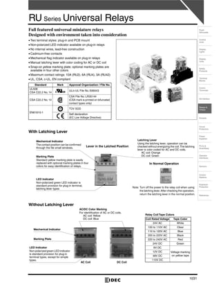
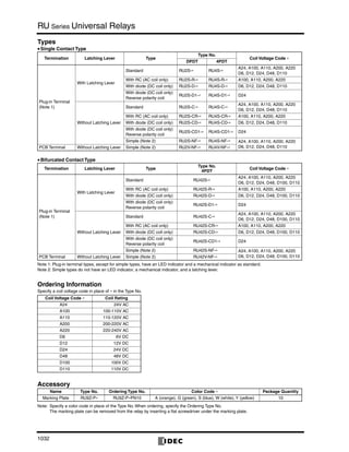
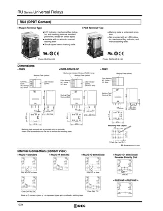
The document provides information on Omron's RU Series universal relays, including:
- The RU Series includes plug-in and PCB mount relays with DPDT, 4PDT, and 4PDT bifurcated contact configurations.
- Features include LED indicators, mechanical flag indicators, latching levers, and marking plates for terminal identification.
- Relays are available with AC or DC coils in various voltage ratings and with surge protection components.
- Contact ratings vary by model with maximum ratings of 10A for DPDT and 6A for 4PDT configurations.
- Specifications include electrical life, operating temperature range, vibration resistance, and more.
This document provides information on the CD4013B and CD4013BC dual D flip-flops. It includes general descriptions, features, applications, connection diagrams, truth tables, and electrical characteristics for the devices. The dual D flip-flops are CMOS integrated circuits that can be used for applications such as shift registers, counters, toggles, automotive systems, data terminals, instrumentation, and computers.
The document provides information on the VARIMETER RCM residual current monitor, including:
1. It has a compact design and can use an external or internal residual current transformer. It detects residual currents according to various standards.
2. It has adjustable tripping values from 10mA to 10A or 30A, a frequency range of 20-2000Hz, and adjustable time delays. It has LED indicators, test and reset buttons, and changeover contacts.
3. It is available in models for mounting in distribution systems or cabinets, with widths of 35mm or 105mm. Models use external or internal residual current transformers.
4. The document provides details on technical specifications, connections, functions,
This document provides information on the CD4093BM CD4093BC Quad 2-Input NAND Schmitt Trigger integrated circuit. It consists of four independent Schmitt trigger NAND gates, each with Schmitt trigger hysteresis on both inputs for noise immunity. The IC has a wide supply voltage range of 3-15V, and specifications for propagation delay, input/output voltage levels and currents, and hysteresis are provided over temperature. Typical applications include wave shaping, pulse generation, and logic functions. Dimensions and packaging options are included.
This document provides specifications for a 120W DIN rail power supply with the following key details:
- It has a single 120W output with a voltage range of 22-28V and a current of 5A.
- The input voltage range is 85-264VAC. It has protections such as overload, overvoltage, and overtemperature protections.
- Additional features include compact design, easy wire connection, 10 year lifetime, shock/vibration resistance, and convection cooling.
The document provides installation and wiring instructions for TECNOLOGIC K series controllers. It specifies that the controller is intended for indoor use and should be mounted in an easily accessible location with minimal vibrations that avoids corrosive gases, water or condensation. Wiring guidelines are provided for different input and output types, including thermocouples, RTDs, voltage/current signals, and relays. Configuration and programming procedures are outlined.
The UTC 4051 is an 8-channel analog multiplexer/demultiplexer chip that allows for digitally controlled switching of analog signals. It has three binary control inputs, an inhibit input, and features low on impedance and very low off leakage current. The chip supports analog signal switching across a wide voltage range of 3V to 18V.
This document provides installation and configuration instructions for TECNOLOGIC K series controllers. It outlines mounting requirements including ambient temperature and humidity limits. It describes input and output wiring diagrams for thermocouples, RTDs, voltage signals, and more. Configuration is protected by passwords and involves modifying parameters to suit the application for items like input type, control strategy, alarms, and outputs.
Cataloge schneider contactor ct-dienhathe.vnDien Ha The
CT contactors can control heating, ventilation, and other systems. They are available in multiple configurations up to 100A and can be equipped with auxiliary functions like indication and time delay. CT+ contactors provide high performance control for demanding applications with characteristics like low noise, temperature rise, and electromagnetic disturbances. Manually-operated contactors allow overriding automatic control.
This document provides installation and configuration instructions for the TECNOLOGIC K series controller. It outlines the mounting requirements including dimensions, environmental conditions and panel thickness. It describes the input/output connections and wiring diagrams. The configuration procedure involves entering password-protected modes to modify parameter groups that control functions like control strategy, alarms and outputs. The factory default parameters can be restored for reconfiguration.
CT contactors can be used to control various electrical loads and circuits. They are available in single-pole, two-pole, three-pole and four-pole configurations ranging from 16 to 100 amps. CT contactors can be equipped with auxiliary functions like indication lights, time delays, and mixed impulse/latched control. They provide reliable operation, with a lifetime of over 5 million switching cycles.
The document describes the JUMPFLEX® 857 Series signal conditioning and relay modules. It provides an overview of the key features and benefits of the modules, including their compact size, flexible jumpering system, configurable settings, safety certification, and support for various signal types. Various models are listed that provide isolation, conditioning, and switching of signals for industrial automation and process control applications.
Ls catalog thiet bi dien electric products e 1104_dienhathe.vnDien Ha The
Khoa Học - Kỹ Thuật & Giải Trí: http://phongvan.org
Tài Liệu Khoa Học Kỹ Thuật: http://tailieukythuat.info
Thiết bị Điện Công Nghiệp - Điện Hạ Thế: http://dienhathe.org
[1] The document provides installation and wiring instructions for TECNOLOGIC K series temperature controllers.
[2] It describes the mounting requirements including ambient temperature and humidity ranges, and notes the instrument is only for indoor use. Wiring diagrams and specifications are provided for different input and output types.
[3] The document also covers the configuration procedure for setting parameters, and lists the technical specifications including dimensions, power supply, accuracy, and ordering codes for different models.
The document summarizes the TPS3617 and TPS3618 battery backup supervisors. The devices monitor a 5V supply and provide a battery backup function to retain RAM data during power faults. When the monitored voltage drops below a threshold, the output switches from the main supply to the backup battery. It also features a watchdog timer and power on reset. The devices are available in an 8-pin MSOP package and operate from -40°C to 85°C. Typical applications include set-top boxes, voice mail systems, portable equipment, and automotive systems.
Original N Channel Mosfet 2SK3566 K3566 3566 2.5A 900V TO-220 NewAUTHELECTRONIC
Original N Channel Mosfet 2SK3566 K3566 3566 2.5A 900V TO-220 New
https://authelectronic.com/original-n-channel-mosfet-2sk3566-k3566-3566-2-5a-900v-to-220-new
K30 controller is intended for permanent installation, for
indoor use only, in an electrical panel which encloses the
rear housing, exposed terminals and wiring on the back.
This document provides specifications for the ACPL-C87B/C87A/C870 precision optically isolated voltage sensor. It includes:
- Key features such as high input impedance, wide operating temperature range, and small package size.
- Electrical specifications including gain accuracy of ±0.5% for the ACPL-C87B, input offset voltage, nonlinearity, and temperature drift.
- Recommended operating conditions and absolute maximum ratings.
- Safety and regulatory approval information for worldwide use.
RunnTech [/rənˈtek/] specializes in research, development and manufacturing joysticks and controllers (Potentiometer or Hall sensors) for industrial applications. All our joysticks and controllers are mainly used in hydraulic proportional control or variable frequency motor control, such as Cranes lifting control, Mine hoisting winch, Scissor Lift, Offshore drilling equipment, Maritime machinery, CNC turning machinery, Rolling mill control desk, Industrial robotics, Welding or Cutting machine, Audio video editing equipments, Photography CCTV control system, Medical imaging system, Loaders, Cranes, Tractors, Harvesters, Excavators, Shield tunneling machine, Rotary table (drilling rig), Electric forklift truck, Aerial work platform, etc.
Orriginal N-Channel Mosfet K3564 3564 2SK3564 TO-220F New ToshibaAUTHELECTRONIC
This document provides specifications for the TOSHIBA 2SK3564 field effect transistor. It is a silicon n-channel MOS transistor intended for switching regulator applications. Key specifications include a low drain-source ON resistance of 3.7 ohms typical, a high forward transfer admittance of 2.6 Siemens typical, and a low leakage current of 100 microamps maximum. Absolute maximum ratings and electrical characteristics are provided along with typical performance curves.
This document provides contact and contactor references for TeSys D Green contactors. It lists contactor models for 3-phase motors from 9A to 150A, along with auxiliary contact blocks, accessories, and mounting systems. Technical specifications are provided for each contactor model, including voltage ratings, current ratings, weight, and fixing options.
CÔNG TY CỔ PHẦN THIẾT BỊ ĐIỆN HOÀNG PHƯƠNG
Địa chỉ: Số 10, ngõ 44, phố Võ Thị Sáu, P.Thanh Nhàn, Q.Hai Bà Trưng, TP. Hà Nội
MST: 0106798886
Điện thoại: 024.3215.1322
Website : Hoangphuongjsc.com
Phone/Zalo : 0944 240 317 / Kinhdoanh1.hpe@gmail.com
Phone/Zalo : 0975 123 698 / Kinhdoanh2.hpe@gmail.com
Phone/Zalo : 0961 008 858 / Kinhdoanh3.hpe@gmail.com
This document provides contact and contactor references for TeSys D Green contactors. It lists contactor models for motor control up to 37 kW and 400V AC-3, including standard power ratings. It also provides information on auxiliary contact blocks, accessories, and coil voltage codes. Dimensions and technical specifications are given for each contactor model.
The document describes the SR30A-AC series brushless servo amplifiers manufactured by Electromate. Key details include:
- The SR30A-AC amplifiers are PWM amplifiers that generate 3-phase sine waves from a resolver input to drive brushless motors.
- Models operate from single or 3-phase 45-270V AC power and provide up to 30A or 15A of continuous current depending on input power.
- Features include regenerative braking, resolver interface, encoder emulation output, and protection from overvoltage, undervoltage, overcurrent and overheating.
- The amplifiers can interface with digital controllers or operate standalone, and include status LEDs and adjustable
Catalog đèn báo nút nhấn công tắc IDEC (Nhật Bản) - dòng TWCTY TNHH HẠO PHƯƠNG
Công ty Cổ phần Hạo Phương xin gửi đến quý khách hàng Catalog về đèn báo, nút nhấn, công tắc xoay Idec (Nhật Bản) phi 22 dòng TW. Catalog chứa đầy đủ thông tin về sản phẩm, kích thước và những lưu ý để sử dụng thiết bị hiệu quả.
Điểm đặc biệt của đèn báo IDEC phi 22 là có thể dễ dàng chuyển đổi từ phi 22 sang phi 25, điều mà hiếm có sản phẩm nào trên thị trường có thể làm được.
The document summarizes specifications for the Aurora Trio 10.0 kW and 12.5 kW three-phase string inverters. It has two independent MPPTs, high maximum efficiency of 97.8%, and wide operating voltage and frequency ranges to optimize energy harvesting. It is designed for outdoor commercial use and includes an electrolyte-free power converter, three-phase bridge topology, and optional integrated DC switch for increased reliability.
This document provides installation and operation instructions for the TECNOLOGIC K48 series temperature controller. It outlines:
1) Mounting requirements for the controller, including ambient temperature and humidity limits.
2) Wiring diagrams and notes for different input types (thermocouples, RTDs, etc.), outputs (relays, SSRs), power supply, and logic inputs.
3) Technical specifications for the controller, including accuracy, display, sampling rate, and certifications.
4) Procedures for configuring the controller, including accessing parameters via passwords and navigating groups to set input type, control strategy, alarms and other functions.
The document provides technical specifications for the RMA42 universal process transmitter including:
- It has 1 or 2 universal inputs that can measure current, voltage, resistance, temperature and includes optional intrinsically safe inputs.
- It has a 5-digit LCD display, 2 limit value relays with an additional status output, and min/max value memory.
- Key specifications include linearization capabilities, 2 calculation channels, 2 relay and 1-2 analog outputs, and dimensions of 45x115x118mm.
The AZB10A20 servo drive is designed to drive brushless and brushed DC motors at high switching frequencies. It has a peak current of 10A, continuous current of 6A, and operates on a supply voltage of 40-175VDC. The drive provides hardware protections and can interface with digital controllers through analog ±10V inputs and outputs.
Ls catalog thiet bi dien electric products e 1104Dien Ha The
Catalog LS, Catalog,
Catalog Thiết Bị Điện LS, Catalog Thiết Bị Điện,
http://dienhathe.com,
Chi tiết các sản phẩm khác của LS tại https://dienhathe.com
Xem thêm các Catalog khác của LS tại https://dienhathe.info
Để nhận báo giá sản phẩm LS vui lòng gọi: 0907.764.966
The AZ60A8DDC is a PWM servo drive designed to drive brush-type DC motors at high switching frequencies. It has a peak current of 60A, continuous current of 30A, and operates from 10-80VDC. The drive provides motor control and protection from overvoltage, undervoltage, overcurrent and more.
This document provides specifications for TE Connectivity's slimline PCN and PCNH series general purpose low power PCB relays. The PCN relay has a 1 pole 5A normally open contact, operates at 120mW, and is only 5mm wide, allowing for high packing density. The PCNH has a single contact and higher performance 180mW coil. Both comply with RoHS and offer cadmium-free contacts. The document provides detailed contact, coil, insulation, mechanical, and other technical data for the relays.
This document provides installation and configuration instructions for the TECNOLOGIC K49 series controller. It outlines:
1) Mounting requirements for the controller, including ambient temperature, humidity, and vibration limits. The controller is intended for indoor use.
2) Wiring diagrams and notes for different input types (thermocouple, RTD, voltage, current) and outputs (relays, SSRs). Proper wiring techniques are emphasized to avoid errors.
3) Technical specifications for the controller, including display type, accuracy, EMC standards, operating temperature, and power supply options. Instructions are provided for ordering controllers with different configurations.
The 25A20DD PWM servo amplifier is designed to drive brush DC motors with up to 25A of peak current. It has adjustable current limits, fault protection, and single supply operation. It interfaces with digital controllers via PWM and direction inputs to control motor speed and direction.
This document provides instructions for installing and wiring a DVP-PLC programmable logic controller. It describes the components of the PLC including status indicators, I/O ports, and expansion ports. Wiring diagrams are provided for connecting the main processing unit, digital I/O expansion units, and power supply modules. Guidelines are given for mounting the PLC enclosure and routing wires. Technical specifications are listed for input/output points, memory, communication ports, operating conditions, and power requirements.
This document provides information on electric equipment including miniature circuit breakers, residual current circuit breakers, and surge protective devices. It includes specifications such as rated current, number of poles, rated voltage, breaking capacity, standards, and dimensions for different product types. Replacement parts and operation status indicators are noted. Product series include BKN, BKH, RKP, BKS, and SP.
Catalog LS, Catalog,
Catalog Thiết Bị Điện LS, Catalog Thiết Bị Điện,
http://dienhathe.com,
Chi tiết các sản phẩm khác của LS tại https://dienhathe.com
Xem thêm các Catalog khác của LS tại https://dienhathe.info
Để nhận báo giá sản phẩm LS vui lòng gọi: 0907.764.966
The SN75176A is a bidirectional transceiver that operates from a single 5V supply. It combines a 3-state differential line driver and differential line receiver. The driver can handle loads up to 60mA and features current limiting and thermal shutdown protection. The receiver has a minimum input impedance of 12kΩ and input sensitivity of ±200mV. It is designed for use on multipoint bus lines in noisy environments.
The TPS65023 is an integrated power management IC that provides three highly efficient step-down converters and two low-dropout regulators. It is designed to power applications running from a single lithium-ion battery cell, such as digital media players and digital cameras. The IC includes a 1.5A step-down converter for the processor core, a 1.2A converter for system voltage, and a 1A converter for memory voltage. It also has a 30mA low-dropout regulator for real-time clock functions and two 200mA general-purpose low-dropout regulators. All components are selectable and configurable through the IC's serial interface.
➒➌➎➏➑➐➋➑➐➐ Satta Matka Dpboss Matka Guessing Indian Matka
KALYAN MATKA | MATKA RESULT | KALYAN MATKA TIPS | SATTA MATKA | MATKA.COM | MATKA PANA JODI TODAY | BATTA SATKA | MATKA PATTI JODI NUMBER | MATKA RESULTS | MATKA CHART | MATKA JODI | SATTA COM | FULL RATE GAME | MATKA GAME | MATKA WAPKA | ALL MATKA RESULT LIVE ONLINE | MATKA RESULT | KALYAN MATKA RESULT | DPBOSS MATKA 143 | MAIN MATKA
➒➌➎➏➑➐➋➑➐➐ Satta Matka Dpboss Matka Guessing Indian Matka KALYAN MATKA | MATKA RESULT | KALYAN MATKA TIPS | SATTA MATKA | MATKA.COM | MATKA PANA JODI TODAY | BATTA SATKA | MATKA PATTI JODI NUMBER | MATKA RESULTS | MATKA CHART | MATKA JODI | SATTA COM | FULL RATE GAME | MATKA GAME | MATKA WAPKA | ALL MATKA RESULT LIVE ONLINE | MATKA RESULT | KALYAN MATKA RESULT | DPBOSS MATKA 143 | MAIN MATKA
➒➌➎➏➑➐➋➑➐➐ Matka Guessing Satta Matka Kalyan panel Chart Indian Matka Satta Matta Matka Dpboss KALYAN MATKA | MATKA RESULT | KALYAN MATKA TIPS | SATTA MATKA | MATKA.COM | MATKA PANA JODI TODAY | BATTA SATKA | MATKA PATTI JODI NUMBER | MATKA RESULTS | MATKA CHART | MATKA JODI | SATTA COM | FULL RATE GAME | MATKA GAME | MATKA WAPKA | ALL MATKA RESULT LIVE ONLINE | MATKA RESULT | KALYAN MATKA RESULT | DPBOSS MATKA 143 | MAIN MATKA
➒➌➎➏➑➐➋➑➐➐ Satta Matka Dpboss Matka Guessing Indian Matka KALYAN MATKA | MATKA RESULT | KALYAN MATKA TIPS | SATTA MATKA | MATKA.COM | MATKA PANA JODI TODAY | BATTA SATKA | MATKA PATTI JODI NUMBER | MATKA RESULTS | MATKA CHART | MATKA JODI | SATTA COM | FULL RATE GAME | MATKA GAME | MATKA WAPKA | ALL MATKA RESULT LIVE ONLINE | MATKA RESULT | KALYAN MATKA RESULT | DPBOSS MATKA 143 | MAIN MATKA
➒➌➎➏➑➐➋➑➐➐ Satta Matka Dpboss Matka Guessing Indian Matka
KALYAN MATKA | MATKA RESULT | KALYAN MATKA TIPS | SATTA MATKA | MATKA.COM | MATKA PANA JODI TODAY | BATTA SATKA | MATKA PATTI JODI NUMBER | MATKA RESULTS | MATKA CHART | MATKA JODI | SATTA COM | FULL RATE GAME | MATKA GAME | MATKA WAPKA | ALL MATKA RESULT LIVE ONLINE | MATKA RESULT | KALYAN MATKA RESULT | DPBOSS MATKA 143 | MAIN MATKA
A Brief Introduction About Hanying Chen_Hanying Chen
Vancouver-based artist Hanying Chen boasts extensive skills in writing, directing, producing, and singing, reflecting her diverse talents in the performing arts. As she looks ahead, Hanying is driven to craft a fulfilling career path that harmonizes with her deep passion for artistic expression. In the coming years, she envisions cultivating a balanced life, blending her professional aspirations with her desire to foster meaningful connections in her vibrant urban community.
➒➌➎➏➑➐➋➑➐➐ Satta Matka Dpboss Matka Guessing Indian Matka
KALYAN MATKA | MATKA RESULT | KALYAN MATKA TIPS | SATTA MATKA | MATKA.COM | MATKA PANA JODI TODAY | BATTA SATKA | MATKA PATTI JODI NUMBER | MATKA RESULTS | MATKA CHART | MATKA JODI | SATTA COM | FULL RATE GAME | MATKA GAME | MATKA WAPKA | ALL MATKA RESULT LIVE ONLINE | MATKA RESULT | KALYAN MATKA RESULT | DPBOSS MATKA 143 | MAIN MATKA
➒➌➍➑➊➑➏➍➋➒ Satta Matka Satta result marka result
Satta Matka Satta result marka result Dpboss sattamatka341 satta143 Satta Matka Sattamatka New Mumbai Ratan Satta Matka Fast Matka Milan Market Kalyan Matka Results Satta Game Matka Game Satta Matka Kalyan Satta Matka Mumbai Main Online Matka Results Satta Matka Tips Milan Chart Satta Matka Boss
New Star Day Satta King Live Satta Matka Results Satta Matka Company Indian Matka Satta Matka Kalyan Night Matka
➒➌➍➑➊➑➏➍➋➒ Satta Matka Satta result marka result
➒➌➎➏➑➐➋➑➐➐ Satta Matka Dpboss Matka Guessing Indian Matka Satta Matta Matka KALYAN MATKA | MATKA RESULT | KALYAN MATKA TIPS | SATTA MATKA | MATKA.COM | MATKA PANA JODI TODAY | BATTA SATKA | MATKA PATTI JODI NUMBER | MATKA RESULTS | MATKA CHART | MATKA JODI | SATTA COM | FULL RATE GAME | MATKA GAME | MATKA WAPKA | ALL MATKA RESULT LIVE ONLINE | MATKA RESULT | KALYAN MATKA RESULT | DPBOSS MATKA 143
➒➌➍➑➊➑➏➍➋➒ Satta Matka Satta result marka result Satta Matka Satta result marka result Dpboss sattamatka341 satta143 Satta Matka Sattamatka New Mumbai Ratan Satta Matka Fast Matka Milan Market Kalyan Matka Results Satta Game Matka Game Satta Matka Kalyan Satta Matka Mumbai Main Online Matka Results Satta Matka Tips Milan Chart Satta Matka Boss New Star Day Satta King Live Satta Matka Results Satta Matka Company Indian Matka Satta Matka Kalyan Night Matka
Kalyan Result Final ank Satta 143 Kalyan final Kalyan panel chart Kalyan Result guessing Time bazar Kalyan guessing Kalyan satta sattamatka
Clouded storyboard why does the title need to be so long
Ru series (1)
1. 1031
Control
Units
Display
Lights
Display
Units
Safety
Products
Terminal
Blocks
Comm.
Terminals
AS-Interface
Relays &
Timers
Sockets
Circuit
Protectors
Power
Supplies
PLCs &
SmartRelay
Operator
Interfaces
Sensors
Control
Stations
Explosion
Protection
References
Flush
Silhouette
RU Series Universal Relays
Full featured universal miniature relays
Designed with environment taken into consideration
• Two terminal styles: plug-in and PCB mount
• Non-polarized LED indicator available on plug-in relays
• No internal wires, lead-free construction
• Cadmium-free contacts
• Mechanical flag indicator available on plug-in relays
• Manual latching lever with color coding for AC or DC coil
• Snap-on yellow marking plate; optional marking plates are
available in four other colors
• Maximum contact ratings: 10A (RU2), 6A (RU4), 3A (RU42)
• UL, CSA, c-UL, EN compliant
With Latching Lever
Without Latching Lever
Standard Mark Approval Organization / File No.
UL508
CSA C22.2 No. 14
UL/c-UL File No. E66043
CSA C22.2 No. 14
CSA File No. LR35144
(CSA mark is printed on bifurcated
contact types only)
EN61810-1
TÜV SÜD
Self declaration
(EC Low Voltage Directive)
Lever in the Latched Position
Mechanical Indicator
The contact position can be confirmed
through the file small windows.
Marking Plate
Standard yellow marking plate is easily
replaced with optional marking plates in four
colors for easy identification of relays.
LED Indicator
Non-polarized green LED indicator is
standard provision for plug-in terminal,
latching lever types
Latching Lever
Using the latching lever, operation can be
checked without energizing the coil.The latching
lever is color coded for AC and DC coils.
AC coil: Orange
DC coil: Green
In Normal Operation
Note: Turn off the power to the relay coil when using
the latching lever.After checking the operation,
return the latching lever in the normal position.
AC/DC Color Marking
For identification of AC or DC coils.
AC coil:Yellow
DC coil: Blue
Mechanical Indicator
Marking Plate
LED Indicator
Non-polarized green LED indicator
is standard provision for plug-in
terminal types, except for simple
types.
AC Coil DC Coil
Relay Coil Tape Colors
Coil Rated Voltage Tape Color
24V AC White
100 to 110V AC Clear
110 to 120V AC Blue
200 to 220V AC Black
220 to 240V AC Red
24V DC Green
6V DC
Voltage marking
on yellow tape
12V DC
48V DC
110V DC
2.
3. RU Series Universal Relays
1032
Types
•••• Single Contact Type
•••• Bifurcated Contact Type
Note 1: Plug-in terminal types, except for simple types, have an LED indicator and a mechanical indicator as standard.
Note 2: Simple types do not have an LED indicator, a mechanical indicator, and a latching lever.
Ordering Information
Specify a coil voltage code in place of ∗ in the Type No.
Accessory
Note: Specify a color code in place of the Type No. When ordering, specify the Ordering Type No.
The marking plate can be removed from the relay by inserting a flat screwdriver under the marking plate.
Termination Latching Lever Type
Type No.
Coil Voltage Code ∗
DPDT 4PDT
Plug-in Terminal
(Note 1)
With Latching Lever
Standard RU2S-∗ RU4S-∗
A24, A100, A110, A200, A220
D6, D12, D24, D48, D110
With RC (AC coil only) RU2S-R-∗ RU4S-R-∗ A100, A110, A200, A220
With diode (DC coil only) RU2S-D-∗ RU4S-D-∗ D6, D12, D24, D48, D110
With diode (DC coil only)
Reverse polarity coil
RU2S-D1-∗ RU4S-D1-∗ D24
Without Latching Lever
Standard RU2S-C-∗ RU4S-C-∗
A24, A100, A110, A200, A220
D6, D12, D24, D48, D110
With RC (AC coil only) RU2S-CR-∗ RU4S-CR-∗ A100, A110, A200, A220
With diode (DC coil only) RU2S-CD-∗ RU4S-CD-∗ D6, D12, D24, D48, D110
With diode (DC coil only)
Reverse polarity coil
RU2S-CD1-∗ RU4S-CD1-∗ D24
Simple (Note 2) RU2S-NF-∗ RU4S-NF-∗ A24, A100, A110, A200, A220
D6, D12, D24, D48, D110PCB Terminal Without Latching Lever Simple (Note 2) RU2V-NF-∗ RU4V-NF-∗
Termination Latching Lever Type
Type No.
4PDT
Coil Voltage Code ∗
Plug-in Terminal
(Note 1)
With Latching Lever
Standard RU42S-∗
A24, A100, A110, A200, A220
D6, D12, D24, D48, D100, D110
With RC (AC coil only) RU42S-R-∗ A100, A110, A200, A220
With diode (DC coil only) RU42S-D-∗ D6, D12, D24, D48, D100, D110
With diode (DC coil only)
Reverse polarity coil
RU42S-D1-∗ D24
Without Latching Lever
Standard RU42S-C-∗
A24, A100, A110, A200, A220
D6, D12, D24, D48, D100, D110
With RC (AC coil only) RU42S-CR-∗ A100, A110, A200, A220
With diode (DC coil only) RU42S-CD-∗ D6, D12, D24, D48, D100, D110
With diode (DC coil only)
Reverse polarity coil
RU42S-CD1-∗ D24
Simple (Note 2) RU42S-NF-∗ A24, A100, A110, A200, A220
D6, D12, D24, D48, D100, D110PCB Terminal Without Latching Lever Simple (Note 2) RU42V-NF-∗
Coil Voltage Code ∗ Coil Rating
A24 24V AC
A100 100-110V AC
A110 110-120V AC
A200 200-220V AC
A220 220-240V AC
D6 6V DC
D12 12V DC
D24 24V DC
D48 48V DC
D100 100V DC
D110 110V DC
Name Type No. Ordering Type No. Color Code ∗ Package Quantity
Marking Plate RU9Z-P∗ RU9Z-P∗PN10 A (orange), G (green), S (blue), W (white), Y (yellow) 10
4. RU Series Universal Relays
1033
Control
Units
Display
Lights
Display
Units
Safety
Products
Terminal
Blocks
Comm.
Terminals
AS-Interface
Relays &
Timers
Sockets
Circuit
Protectors
Power
Supplies
PLCs &
SmartRelay
Operator
Interfaces
Sensors
Control
Stations
Explosion
Protection
References
Flush
Silhouette
Coil Ratings
Note 1: The rated current includes the current draw by the LED indicator.
Note 2: Rated voltage 100V DC is available for the bifurcated contact type only.
Rated Voltage (V)
Coil
Voltage
Code
Rated Current (mA)
±15% (at 20°C) Coil Resistance (Ω)
±10% (at 20°C)
Operating Characteristics (against rated values at 20°C)
Maximum Continuous
Applied Voltage
Minimum Pickup
Voltage
Dropout Voltage
50 Hz 60 Hz
AC
(50/60 Hz)
24 A24 49.3 42.5 164
110% 80% maximum 30% minimum
100-110 A100 9.2-11.0 7.8-9.0 3,460
110-120 A110 8.4-10.0 7.1-8.2 4,550
200-220 A200 4.6-5.5 4.0-4.6 14,080
220-240 A220 4.2-5.0 3.6-4.2 18,230
DC
6 D6 155 40
110% 80% maximum 10% minimum
12 D12 80 160
24 D24 44.7 605
48 D48 18 2,560
100 D100 9.7 10,000
110 D110 8.9 12,100
Contact Ratings
Note 1: On 4PDT relays, the maximum allowable total current of neighboring
two poles is 6A. At the rated load, make sure that the total current of
neighboring two poles does not exceed 6A (3A + 3A = 6A).
Note 2: Inductive load for the rated load — cos ø = 0.3, L/R = 7 ms
•••• UL and c-UL Ratings
•••• CSA Ratings
•••• TÜV Ratings
Surge Suppressor Ratings
Specifications
Note: Above values are initial values.
∗1: Measured using 5V DC, 1A voltage drop method
∗2: Measured at operating frequency of 120 operations/min (failure rate level
P, reference value)
∗3: Measured at the rated voltage (at 20°C), excluding contact bouncing;
Release time of AC relays with RC: 25 ms maximum
Release time of DC relays with diode: 40 ms maximum
∗4: Contact Load and Electrical Life (at ambient temperature 20°C)
∗5: Measured at the rated voltage. Simple types include plug-in terminal sim-
ple types and all PCB terminal types.
Contact
Continu-
ous
Current
Allowable Contact Power
Voltage
(V)
Rated Load
Res.
Load
Ind.
Load
Resistive
Load
Inductive
Load
DPDT 10A 2500VA AC
300W DC
1250VA AC
150W DC
250 AC 10A 5A
30 DC 10A 5A
4PDT 6A
1500VA AC
180W DC
600VA AC
90W DC
250 AC 3A 0.8A
30 DC 3A 1.5A
4PDT
bifurcated 3A
750VA AC
90W DC
200VA AC
45W DC
250 AC 3A 0.8A
30 DC 3A 1.5A
Voltage
Resistive General Use Horse Power Rating
RU2 RU4 RU42 RU2 RU4 RU42 RU2 RU4 RU42
250V AC 10A — 3A — 6A — — 1/10HP —
30V DC 10A 6A 3A — — — — — —
Voltage
Resistive
RU42
250V AC 3A
30V DC 3A
Voltage
Resistive Inductive
RU2 RU4 RU42 RU2 RU4 RU42
250V AC 10A 6A 3A 5A 0.8A 0.8A
30V DC 10A 6A 3A 5A 1.5A 1.5A
Type Ratings
AC Coil With RC RC series circuit
R: 20 kΩ, C: 0.033 μF
DC Coil With Diode Diode reverse voltage: 1000V
Diode forward current: 1A
Type (Contact) RU2 (DPDT) RU4 (4PDT) RU42 (4PDT)
Contact Material Silver alloy
Silver
(gold clad)
Silver-nickel
(gold clad)
Contact
Resistance ∗1
50 mΩ maximum
Minimum
Applicable Load ∗2
24V DC, 5 mA 1V DC, 1 mA 1V DC, 0.1 mA
(reference value)
Operate Time ∗3 20 ms maximum
Release Time ∗3 20 ms maximum
Power
Consumption
AC: 1.1 to 1.4VA (50 Hz), 0.9 to 1.2VA (60 Hz)
DC: 0.9 to 1.0W
Insulation
Resistance
100 MΩ minimum (500V DC megger)
Dielectric Strength
Between contact and coil: 2500V AC, 1 minute
Between contacts of different poles:
2500V AC,
1 minute
2000V AC, 1 minute
Between contacts of the same pole:
1000V AC, 1 minute
Operating
Frequency
Electrical: 1800 operations/h maximum
Mechanical: 18,000 operations/h maximum
Vibration
Resistance
Damage limits: 10 to 55 Hz, amplitude 0.5 mm
Operating extremes: 10 to 55 Hz, amplitude 0.5 mm
Shock Resistance
Damage limits: 1000 m/s2
Operating extremes: 150 m/s2
Mechanical Life
AC: 50,000,000 operations
DC: 100,000,000 operations
50,000,000
operations
Electrical Life ∗4 See table below
Operating
Temperature ∗5
Simple types: –55 to +70°C (no freezing)
Others: –55 to +60°C (no freezing)
Operating Humidity 5 to 85% RH (no condensation)
Weight Approx. 35g
Type Voltage Resistive Load
Inductive Load
(cos ø = 0.3, L/R = 7 ms)
Electrical Life
(operations minimum)
RU2
250V AC
10A 5A 100,000
5A 2.5A 500,000
30V DC
10A 5A 100,000
5A 2.5A 500,000
110V DC 0.6A 0.4A 100,000
RU4
250V AC
6 2.6A 50,000
3A 0.8A 200,000
30V DC
6A 2.7A 50,000
3A 1.5A 200,000
110V DC
0.65A 0.33A 50,000
0.33A 0.18A 200,000
RU42
250V AC 3A 0.8A 100,000
30V DC 3A 1.5A 100,000
110V DC 0.44A 0.22A 100,000
5. RU Series Universal Relays
1034
Dimensions
Internal Connection (Bottom View)
RU2 (DPDT Contact)
•••• Plug-in Terminal Type •••• PCB Terminal Type
• LED indicator, mechanical flag indica-
tor, and marking plate are standard
provisions, except on simple types.
• Available with or without a manual
latching lever
• Simple types have a marking plate.
• Marking plate is a standard provi-
sion.
• Not provided with an LED indica-
tor, mechanical flag indicator, and
manual latching lever.
Photo: RU2S-A100 Photo: RU2V-NF-A100
Latching
Lever
AC: Orange
DC: Green
Marking Plate (yellow)
ø1.2 × 2.2 Hole
LED Indicator
(green)
35.06.4
2.60.5
27.5
21.0
14
58
912
1314
8-ø1 Holes
27.5
12.74.1
6.4
7.0
13.2
0.8
13.2
2.6
4.0
0.5
21.0
0.5
35.0Mounting Hole Layout
Marking Plate (yellow)
Marking Plate
Removal Slot
Color Marking
AC: Yellow
DC: Blue
27.5
Marking Plate
Removal Slot
Color Marking
AC: Yellow
DC: Blue
14
58
912
1314
35.06.4
2.6
0.5
21.0
ø1.2 × 2.2 Hole
LED Indicator
(green)
(RU2S-C only)
Mechanical Indicator Window (RU2S-C only)
Marking Plate (yellow)
•••• RU2S •••• RU2S-C/RU2S-NF •••• RU2V
Marking plate removal slot is provided only on one side.
Insert a flat screwdriver into the slot to remove the marking plate.
All dimensions in mm.
(14)A2(13)A1
(12)41(9)11
(8)44(5)14
(4)42(1)12
Over 24V AC/DC
24V AC/DC or less
(13)A1 (14)A2
(1)12 (4)42
(5)14 (8)44
(9)11 (12)41
(14)A2(13)A1
(12)41(9)11
(8)44(5)14
(4)42(1)12
(1)12 (4)42
(5)14 (8)44
(9)11 (12)41
(13)A1 (14)A2
Over 24V DC
24V DC or less
(14)A2(13)A1
(12)41(9)11
(8)44(5)14
(4)42(1)12
(14)A2(13)A1
24V DC
(12)41(9)11
(8)44(5)14
(4)42(1)12
(14)A2(13)A1
(12)41(9)11
(8)44(5)14
(4)42(1)12
•••• RU2S-∗∗∗∗ Standard •••• RU2S-∗∗∗∗R With RC •••• RU2S-∗∗∗∗D With Diode •••• RU2S-∗∗∗∗D1 With Diode
Reverse Polarity Coil
•••• RU2S-NF-∗∗∗∗/RU2V-NF-∗∗∗∗
Blank or C comes in place of ∗ to represent types with or without a latching lever.
6. RU Series Universal Relays
1035
Control
Units
Display
Lights
Display
Units
Safety
Products
Terminal
Blocks
Comm.
Terminals
AS-Interface
Relays &
Timers
Sockets
Circuit
Protectors
Power
Supplies
PLCs &
SmartRelay
Operator
Interfaces
Sensors
Control
Stations
Explosion
Protection
References
Flush
Silhouette
Electrical Life Curves
Maximum Switching Current
Ambient Temperature vs.Temperature Rise Curves
10
1000
100
1
10510.50.1
110V DC
30V DC
250V AC
Load Current (A)
(×10,000operations)
0.1 0.5 1 5 10
1
100
1000
10
110V DC
250V AC/30V DC
Load Current (A)
(×10,000operations)
DC: L/R = 7 ms
AC: cos ø = 0.3
•••• RU2 (Resistive Load) •••• RU2 (Inductive Load)
10
5
0.1
1
10 30 100 250 500
AC resistive
AC inductive
(cos ø = 0.3)
Load Voltage (V)
LoadCurrent(A)
DC resistive
DC inductive
L/R = 7 ms
•••• RU2
120
110
100
90
80
70
60
50
40
30
20
10
706050403020100
Ambient Temperature (°C)
TemperatureRise(°C)
Load current
5A × 2 poles
Load current
10A × 2 poles
No load current
0 10 20 30 40 50 60 70
10
20
30
40
50
60
70
80
90
100
110
120
Ambient Temperature (°C)
TemperatureRise(°C)
Load current
5A × 2 poles
Load current
10A × 2 poles
No load current
0 10 20 30 40 50 60 70
10
20
30
40
50
60
70
80
90
100
110
120
Ambient Temperature (°C)
TemperatureRise(°C)
Load current
5A × 2 poles
Load current
10A × 2 poles
No load current
•••• RU2 (AC Coil, 50 Hz) •••• RU2 (AC Coil, 60 Hz) •••• RU2 (DC Coil)
The above temperature rise curves show the characteristics when 100% the rated coil voltage is applied.
The heat resistance of the coil is 120°C. The slant dashed line indicates the allowable temperature rise for the coil at different ambient temperatures.
7. RU Series Universal Relays
1036
Dimensions
Internal Connection (Bottom View)
RU4 (4PDT Contact)
•••• Plug-in Terminal Type •••• PCB Terminal Type
• LED indicator, mechanical flag indica-
tor, and marking plate are standard
provisions, except on simple types.
• Available with or without a manual
latching lever
• Simple types have a marking plate.
• Marking plate is a standard provi-
sion.
• Not provided with an LED indica-
tor, mechanical flag indicator, and
manual latching lever.
Photo: RU42S-A100 Photo: RU4V-NF-D24
(RU4)
(RU42)
3-4.4
0.8
2.6
4.0
0.5
0.5
27.5
21.0
13.27.0
6.4
4.1 12.7
4.435.0
14-ø1 HolesMounting Hole Layout
Marking Plate (yellow)
Marking Plate
Removal Slot
Color Marking
AC: Yellow
DC: Blue
•••• RU4S/RU42S •••• RU4S-C/RU4S-NF
RU42S-C/RU42S-NF
•••• RU4V/RU42V
Marking plate removal slot is provided only on one side.
Insert a flat screwdriver into the slot to remove the marking plate.
All dimensions in mm.
1413
1211109
8765
4321
6.4
21.0
27.5
0.5 2.6
35.0
Latching
Lever
AC: Orange
DC: Green
ø1.2 × 2.2 Hole
LED Indicator
(green)
Marking Plate
Removal Slot
Mechanical Indicator Window
Marking Plate (yellow)
6.4
0.5
2.6
35.0
27.5
21.0
Marking Plate
Removal Slot
Color Marking
AC: Yellow
DC: Blue
ø1.2 × 2.2 Hole
LED Indicator
(green)
(RU4S-C/
RU42S-C only)
Marking Plate (yellow)
1413
1211109
8765
4321
Mechanical Indicator Window
(RU4S-C/RU42S-C only)
(1)12 (2)22 (3)32 (4)42
(5)14 (6)24 (7)34 (8)44
(9)11 (10)21 (11)31 (12)41
(13)A1 (14)A2
Over 24V AC/DC
(14)A2(13)A1
(12)41(11)31(10)21(9)11
(8)44(7)34(6)24(5)14
(4)42(3)32(2)22(1)12
24V AC/DC or less
(14)A2(13)A1
(12)41(11)31(10)21(9)11
(8)44(7)34(6)24(5)14
(4)42(3)32(2)22(1)12
Over 24V DC
(14)A2(13)A1
(12)41(11)31(10)21(9)11
(8)44(7)34(6)24(5)14
(4)42(3)32(2)22(1)12
24V DC or less
(14)A2
(1)12 (2)22 (3)32 (4)42
(5)14 (6)24 (7)34 (8)44
(9)11 (10)21 (11)31 (12)41
(13)A1
24V DC
(1)12 (2)22 (3)32 (4)42
(5)14 (6)24 (7)34 (8)44
(9)11 (10)21 (11)31 (12)41
(13)A1 (14)A2
(14)A2(13)A1
(12)41(11)31(10)21(9)11
(8)44(7)34(6)24(5)14
(4)42(3)32(2)22(1)12
•••• RU4S-∗∗∗∗/RU42S-∗∗∗∗
Standard
•••• RU4S-∗∗∗∗R/RU42S-∗∗∗∗R
With RC
•••• RU4S-∗∗∗∗D/RU42S-∗∗∗∗D
With Diode
•••• RU4S-∗∗∗∗D1/RU42S-∗∗∗∗D1
With Diode
Reverse Polarity Coil
•••• RU4S-NF-∗∗∗∗/RU4V-NF-∗∗∗∗
RU42S-NF-∗∗∗∗/RU42V-NF-∗∗∗∗
Blank or C comes in place of ∗ to represent types with or without a latching lever.
8. RU Series Universal Relays
1037
Control
Units
Display
Lights
Display
Units
Safety
Products
Terminal
Blocks
Comm.
Terminals
AS-Interface
Relays &
Timers
Sockets
Circuit
Protectors
Power
Supplies
PLCs &
SmartRelay
Operator
Interfaces
Sensors
Control
Stations
Explosion
Protection
References
Flush
Silhouette
Electrical Life Curves
Maximum Switching Current
Ambient Temperature vs.Temperature Rise Curves
6310.50.1
10
1000
100
1
110V DC
30V DC
250V AC
Load Current (A)
(×10,000operations)
60.1 0.5 1 3
1
100
1000
10
110V DC
30V DC
250V AC
Load Current (A)
(×10,000operations)
DC: L/R = 7 ms
AC: cos ø = 0.3
10
100
1
0.02 6310.50.1
110V DC
30V DC
250V AC
Load Current (A)
(×10,000operations)
1
100
10
0.1 0.50.02
Load Current (A)
(×10,000operations)
DC: L/R = 7 ms
AC: cos ø = 0.3
110V DC
30V DC
250V AC
•••• RU4 (Resistive Load) •••• RU4 (Inductive Load)
•••• RU42 (Resistive Load) •••• RU42 (Inductive Load)
6
3
0.1
1
10 30 100 250 500
AC inductive
(cos ø = 0.3)
DC resistive
DC inductive
L/R = 7 ms
AC resistive
Load Voltage (V)
LoadCurrent(A)
6
3
0.1
1
10 30 100 250 500
DC inductive
L/R = 7 ms
AC inductive
(cos ø = 0.3)
AC resistive
Load Voltage (V)
LoadCurrent(A)
DC resistive
6
3
0.1
1
10 30 100 250 500
DC inductive
L/R = 7 ms
AC inductive
(cos ø = 0.3)
AC resistive
Load Voltage (V)
LoadCurrent(A)
DC resistive
•••• RU4 (Rated Load) •••• RU4 (Maximum Load) •••• RU42
0 10 20 30 40 50 60 70
10
20
30
40
50
60
70
80
90
100
110
120
Ambient Temperature (°C)
TemperatureRise(°C)
Load current
3A × 4 poles
Load current
6A × 2 poles
No load current
120
110
100
90
80
70
60
50
40
30
20
10
706050403020100
Ambient Temperature (°C)
TemperatureRise(°C)
Load current
3A × 4 poles
Load current
6A × 2 poles
No load current
120
110
100
90
80
70
60
50
40
30
20
10
706050403020100
Ambient Temperature (°C)
TemperatureRise(°C)
Load current
3A × 4 poles
Load current
6A × 2 poles
No load current
•••• RU4/RU42 (AC Coil, 50 Hz) •••• RU4/RU42 (AC Coil, 60 Hz) •••• RU4/RU42 (DC Coil)
The above temperature rise curves show the characteristics when 100% the rated coil voltage is applied.
Load current 6A × 2 poles is for the RU4 types only.
The heat resistance of the coil is 120°C. The slant dashed line indicates the allowable temperature rise for the coil at different ambient temperatures.