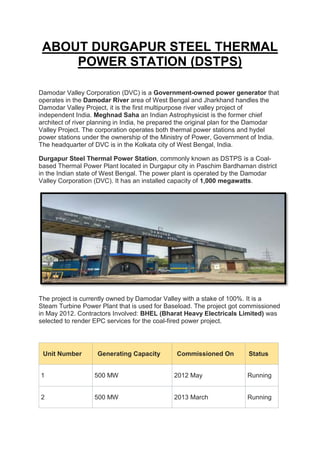
The document provides information about a thermal power plant manual prepared by undergraduate students for the Durgapur Steel Thermal Power Station in West Bengal, India. It is a coal-based thermal power plant owned by the Damodar Valley Corporation. The summary includes:
1) The manual was prepared by undergraduate students to summarize their study of how the steel thermal power plant operates, its components, and how they work based on information from engineers, employees, and surveys.
2) The power plant has two units with a total installed capacity of 1000 megawatts and is used for baseload power generation.
3) Safety is the top priority at the plant given the various hazards. Identification of hazards and risk


![WATER PACKAGE
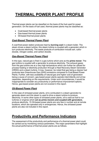
The working fluid of this power plant is water. As the name suggests Damodar
Valley Corporation (DVC), its main source is the Damodar River. From the river
through a raw water intake pump the water is pumped into huge open reservoirs.
There are two reservoirs in DVC. As per requirement water from the reservoir is sent
through a net for primary filtration, to a pump house. There are three pumps
operating in the raw water pump house.
1. PTP-DM Water Pump [Pre-Treatment Plant De-Mineralized Water Pump] (x2)
[A & B]
2. PTP-CW Pump [Pre-Treatment Plant Cooling Water Pump] (x3) [A, B, C]
3. Ash makeup pump (x2) [A & B]
No pre-treatment of water is required for the part of ash handling.
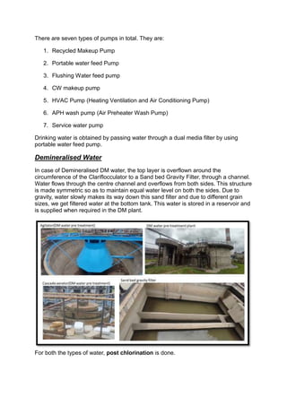
Water is first pumped up to the cascade aerator by PTP-CW Pump and PTP-DM
Water pump. In total there are 2 Cascade aerators, one for DM water plant and the
other for cooling water (e.g., service water, cooling water, portable water, flushing
water, etc…). Cascade aerator is an open head structure with a large surface area
where the inlet pipe is kept vertical and is located at the bottom centre of the
structure. Water with huge pressure energy flows in the aerator as a result the
surface area of water also increases. This water with a large surface area comes
in contact with air and the dissolved unwanted gasses are removed. The other
function is to increase the oxygen content of water. This process also removes CO2,
thus corrosive characteristics of water are also reduced. This whole process is called
aeration. Before moving to the next stage, chlorine is added to the water to kill
bacteria and it is known as pre-chlorination.](https://image.slidesharecdn.com/arghya2-231107155826-b3d21164/85/Thermal-Power-Plant-Training-Report-at-DSTPS-14-320.jpg)


![ANPARA THERMAL POWER STATION[1] sangam.pdf](https://cdn.slidesharecdn.com/ss_thumbnails/anparathermalpowerstation1sangam-251121115219-9261cde4-thumbnail.jpg?width=640&height=640&fit=bounds)


