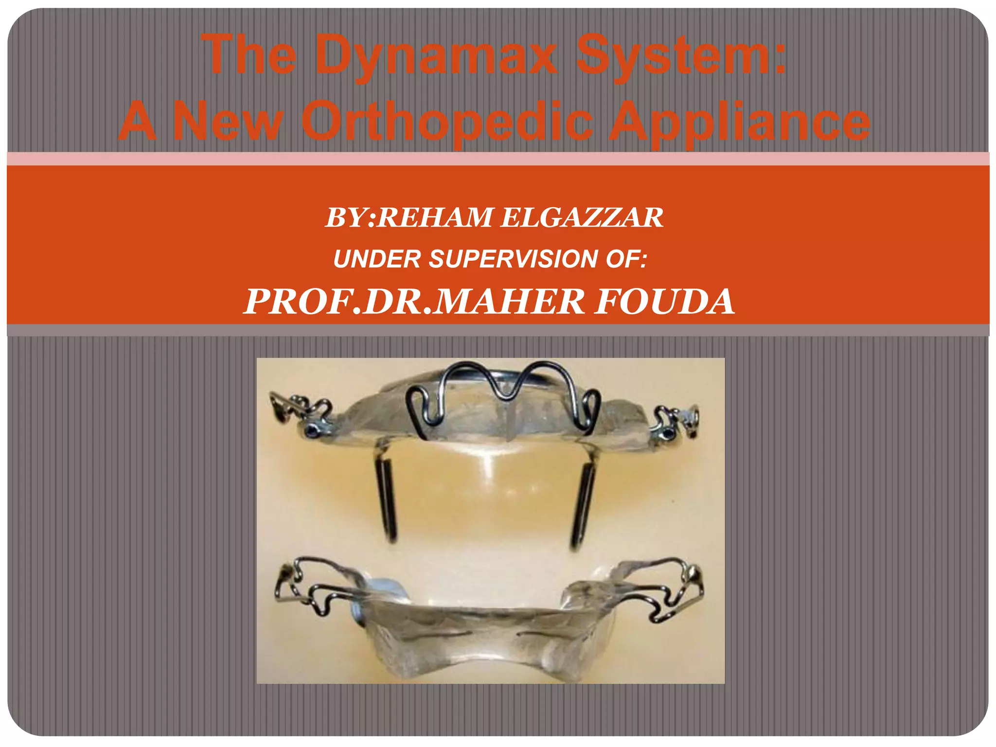
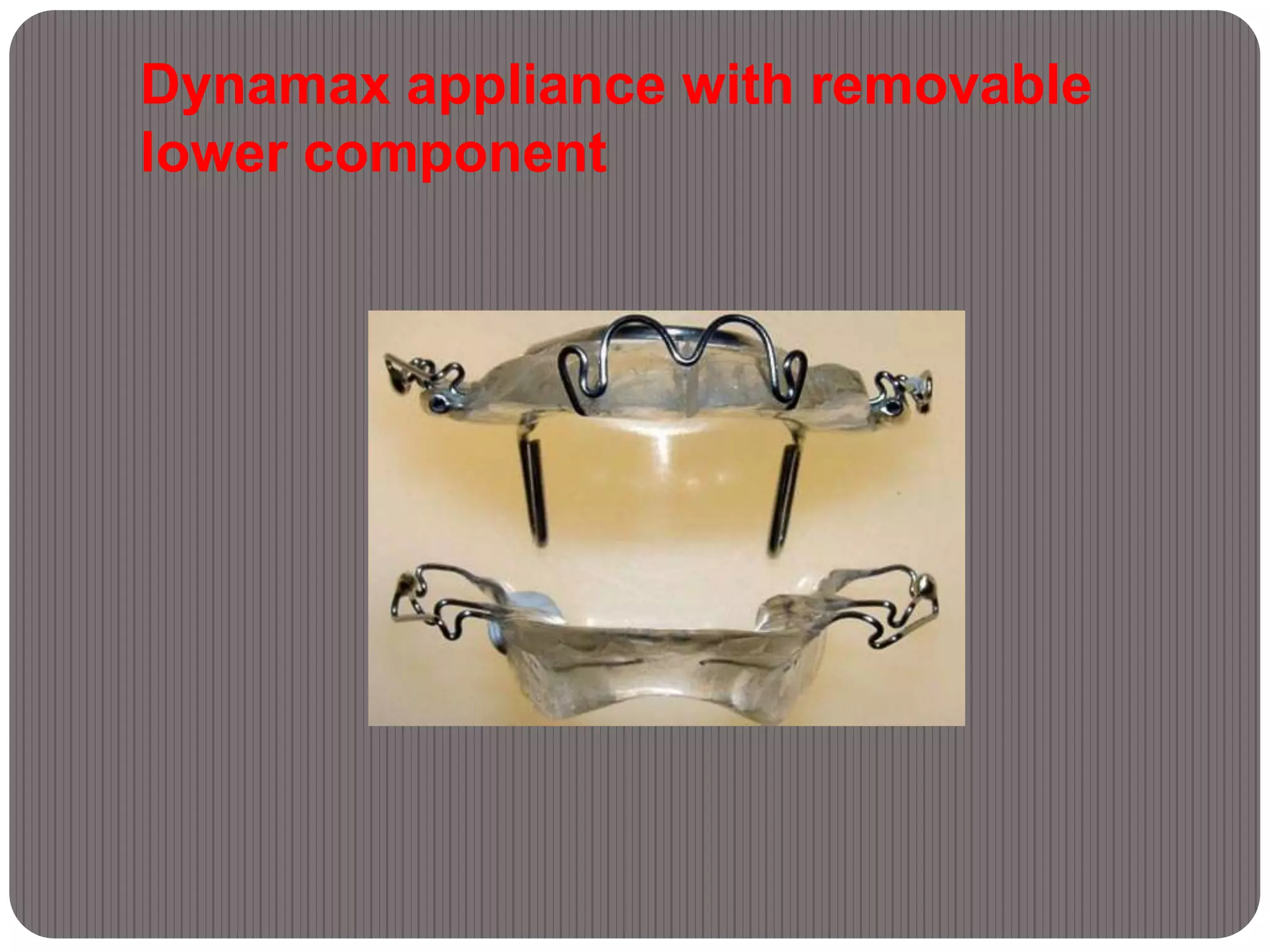
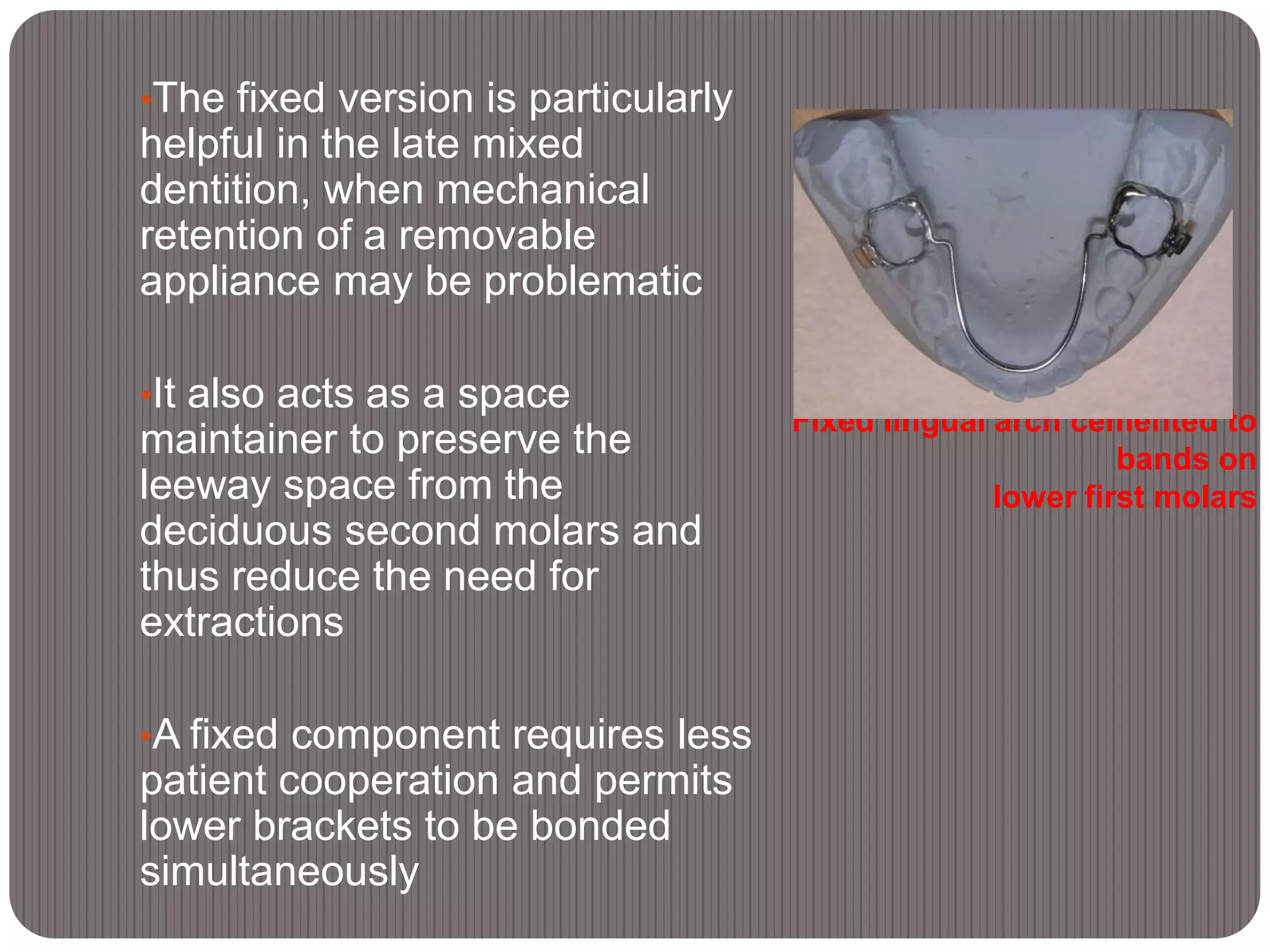
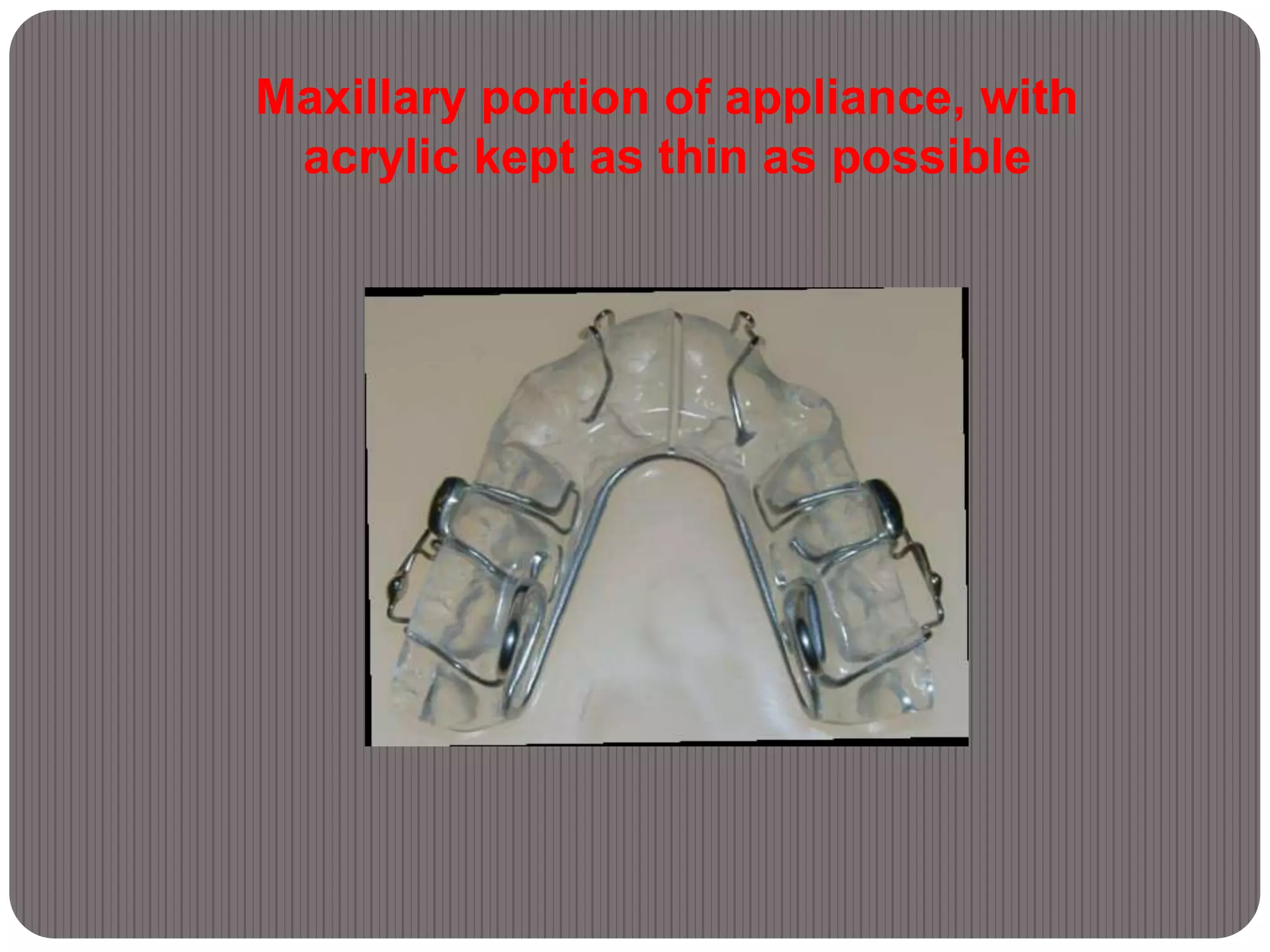
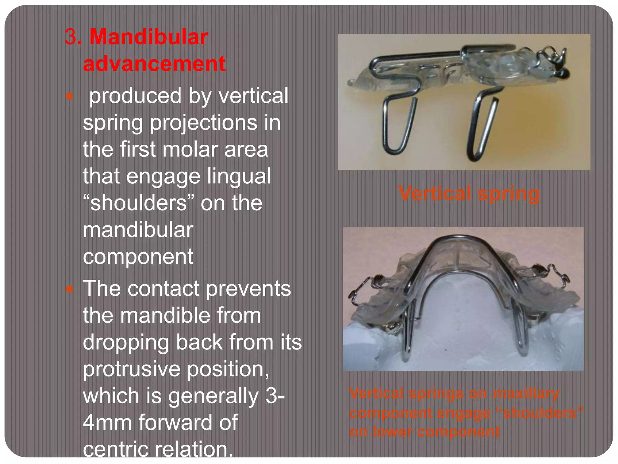
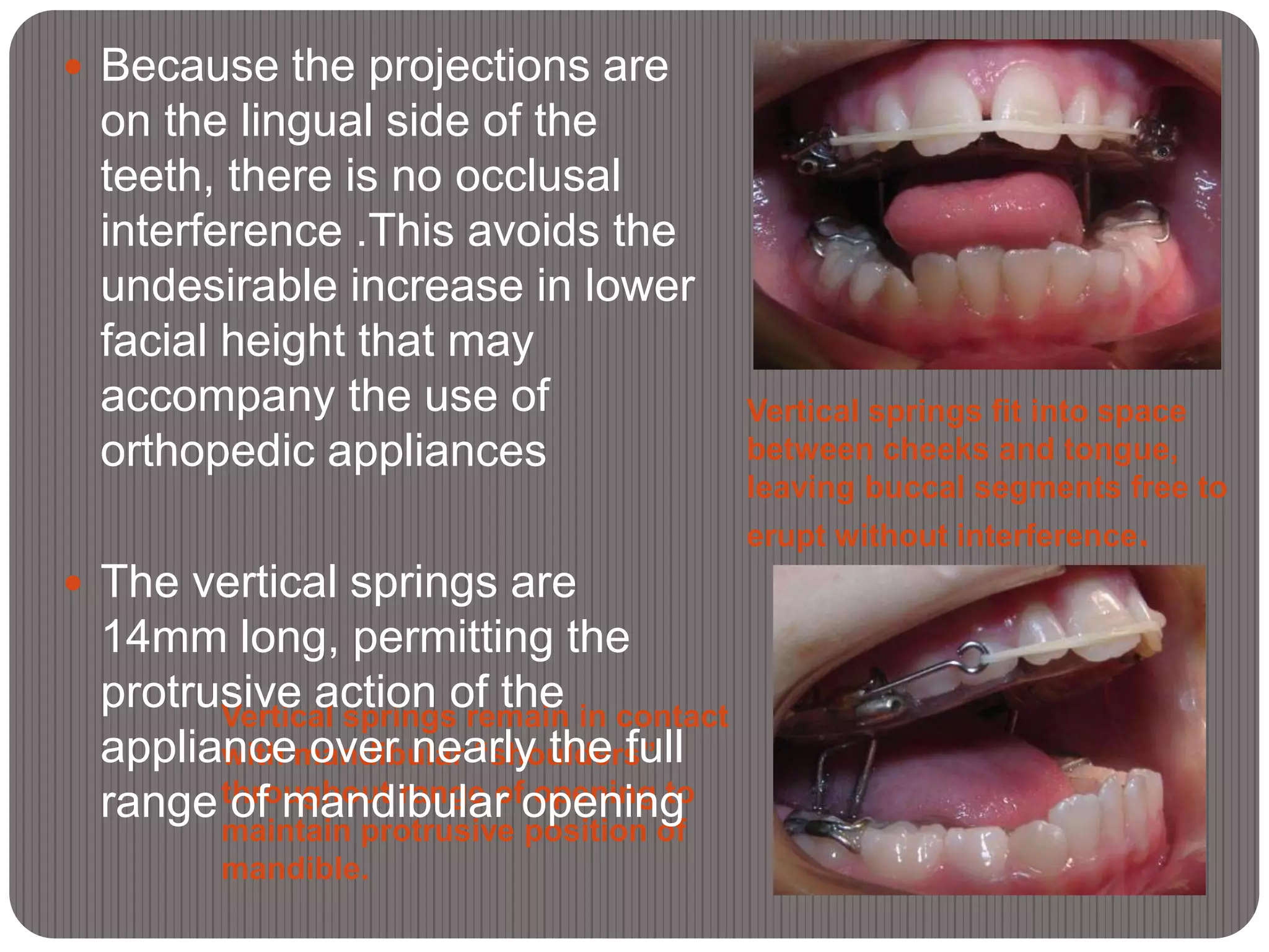
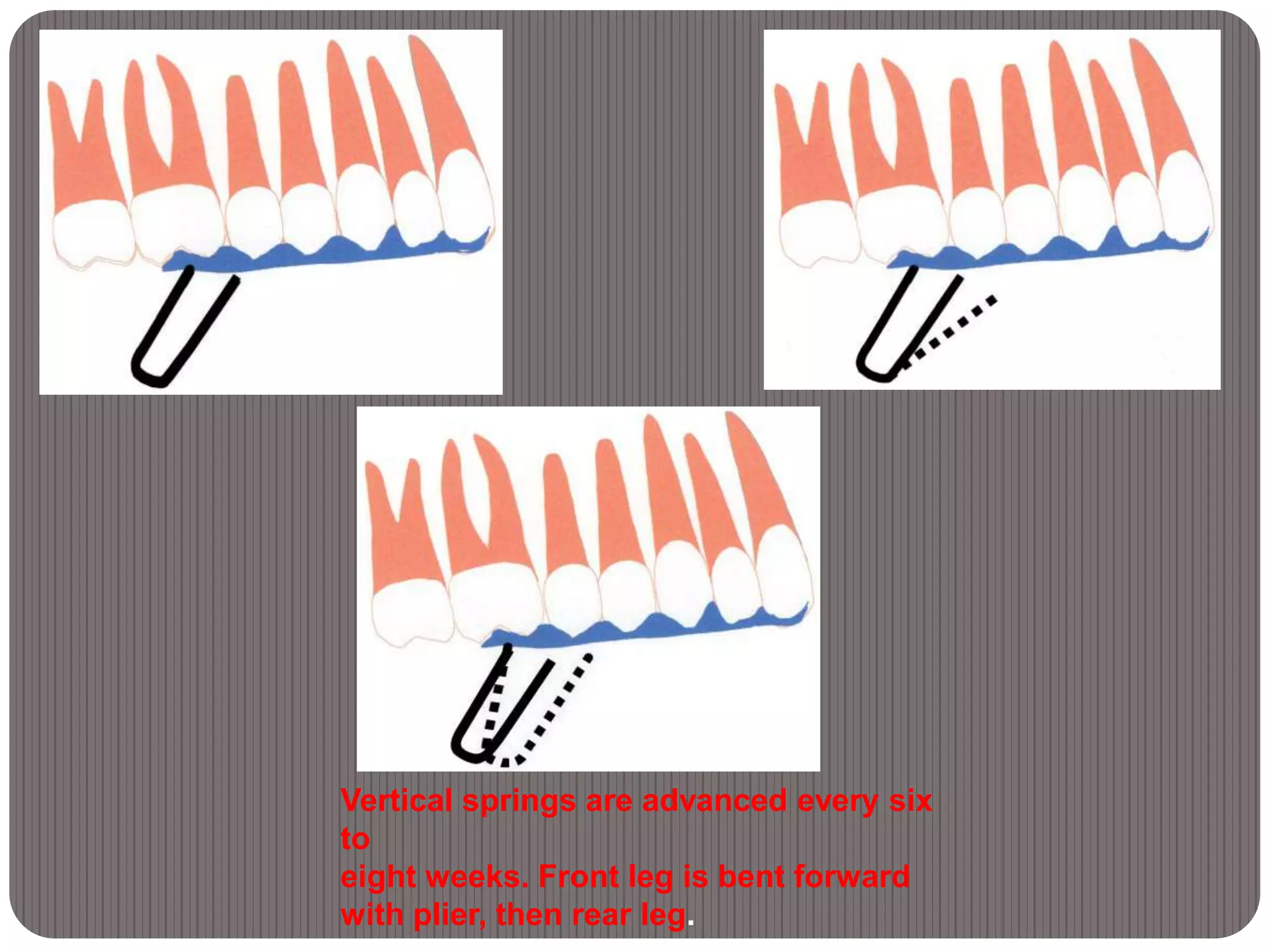
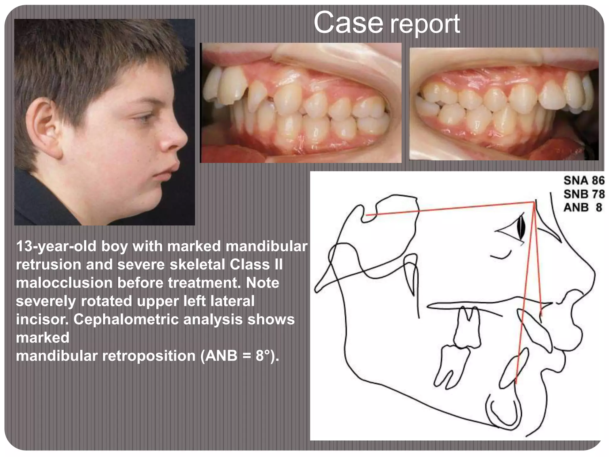
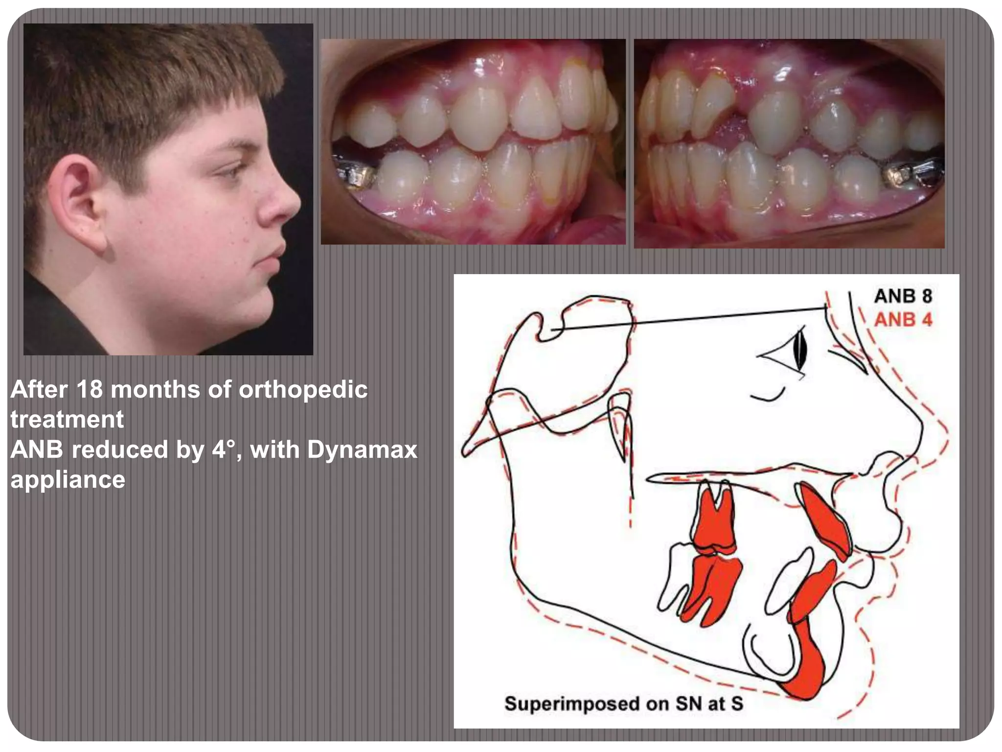
BY:REHAM ELGAZZAR
UNDER SUPERVISION OF:
PROF.DR.MAHER FOUDA
The Dynamax System:
A New Orthopedic Appliance
INTRODUCTION
 Skeletal Class II treatment requires harmonization
of the structures supporting the dentition, as well
as tooth movement, if an esthetic facial
appearance is to be achieved for the patient.
 Harmonized skeletal bases need less tooth
movement and, in particular, less incisor root
movement to produce the dental correction.
Therefore, two-phase treatment, beginning with a
first stage of orthopedic therapy, is now a useful
approach.
 Although a number of appliances are available for
orthopedic or functional therapy, many of these
are relatively inefficient or have unfavorable
dentoalveolar side effects.
 A new design for treatment of skeletal class II is
introduced which is called DYNAMAX
APPLIANCE
Appliance Design
 The Dynamax appliance has two components:
1. The upper part is removable.
2. The lower can be either removable or
fixed as a lingual arch with bands cemented
to the first molars.
Dynamax appliance with removable
lower component
Fixed lingual arch cemented to
bands on
lower first molars
•The fixed version is particularly
helpful in the late mixed
dentition, when mechanical
retention of a removable
appliance may be problematic
•It also acts as a space
maintainer to preserve the
leeway space from the
deciduous second molars and
thus reduce the need for
extractions
•A fixed component requires less
patient cooperation and permits
lower brackets to be bonded
simultaneously
Maxillary Component
1. Retention by means of Adams clasps on the
first molars.
 clasps on the deciduous second molars or
second premolars are optional
 Acrylic capping of the buccal segments and
incisors may be used for added retention, or
instead of clasps to make a simplified version
when retention is not a problem
2. Maxillary expansion, produced by a palatal
Spring.
 This is generally required to avoid the
development of
posterior crossbite as the mandible grows forward It
also provides more space in the maxillary arch.
Maxillary portion of appliance, with
acrylic kept as thin as possible
Vertical spring
Vertical springs on maxillary
component engage “shoulders”
on lower component
3. Mandibular
advancement
 produced by vertical
spring projections in
the first molar area
that engage lingual
“shoulders” on the
mandibular
component
 The contact prevents
the mandible from
dropping back from its
protrusive position,
which is generally 3-
4mm forward of
centric relation.
Vertical springs remain in contact
with mandibular “shoulders”
throughout range of opening to
maintain protrusive position of
mandible.
Vertical springs fit into space
between cheeks and tongue,
leaving buccal segments free to
erupt without interference.
 Because the projections are
on the lingual side of the
teeth, there is no occlusal
interference .This avoids the
undesirable increase in lower
facial height that may
accompany the use of
orthopedic appliances
 The vertical springs are
14mm long, permitting the
protrusive action of the
appliance over nearly the full
range of mandibular opening
4. Occlusal coverage of the upper posterior teeth
with a 1mm thickness of acrylic which has the
following effects
 Unlocks the occlusion, allowing the mandible to
develop forward without interference from the cusps
of the posterior teeth
 Distributes the extraoral forces across all the upper
teeth, reducing the pressure on individual teeth to a
comfortable level.
 Allows eruption of the posterior teeth to be controlled
and, if necessary, completely prevented by varying
the thickness of the posterior capping up to the width
of the interocclusal freeway space..
Acrylic thickness of 1mm over posterior
teeth unlocks occlusion and allows application of
heavy extraoral force to control maxillary development
Anterior torquing spring
controls angulation of maxillary
incisors and prevents tipping
5. Anterior torque control
Anterior torque control with
the torquing spring, which
lies comfortably flat
against the facial surfaces
of the incisors
 Excessive palatal tipping
of the upper incisors, by
trapping the lower incisors,
prevents full forward
development of the
mandible and
compromises the balance
of the facial profile.
Facial elastic
 When less torque control
is required,2.5mm acrylic
capping of the incisal
edges can be used
instead of the spring.
 If the incisors are
proclined to start with,
the spring and the
capping can be left off
and the proclination
corrected with a facial
elastic stretched from
canine to canine
Facebow connected to tubes in
second premolar region
Posterior high-pull headgear
attached to facebow.
Extraoral traction
 Extraoral traction with a
posterior high-pull
headgear to tubes in
the second premolar
region, if desired
 Heavy forces of as
much as1,000g per side
can control the vertical
development of the face
and, with acrylic
coverage of the
posterior teeth, can be
used without patient
discomfort.
Mandibular Component
Capping lower incisors
improves retention and controls
tipping
 The removable type
comprises
1. Retention with Adams or
Crozat clasps on the first
molars and, if necessary, on
the second
deciduous molars
 Capping the lower incisors is
helpful to improve retention
and to control tipping of
these teeth
 Where there is a deep
curve of Spee and eruption of
the posterior teeth is
required, the lower incisors
Lip bumper may be added for
soft-tissue control and
increased anchorage.
“Shoulders” in lingual acrylic of
removable lower component.
 2. An acrylic body extending
as far down the lingual of
the mandible as possible,
without
overextending and causing
trauma
 3. Acrylic “shoulders”, 3mm
deep, mesial to the first
molars .These contact the
vertical springs on the upper
appliance to set the forward
position of the mandible.
 4. A lip bumper, with the
Fixed lingual arch cemented to
bands on lower first molars,
with “shoulders” bent into wire
mesial to bands
 The fixed mandibular
appliance is similar to
a standard lingual
arch, with bands
cemented to the first
molars, but with 3mm
“shoulders” bent
mesial to the bands .
 The bands should
preferably be .010",
instead of the usual
.007", to avoid
splitting.
Appliance Construction
Prefabricated wire form
simplifies appliance
construction.
 Prefabricated wires are used for
both the vertical springs and the
expansion element, making
laboratory construction
uncomplicated
 Adjustment is simple, usually
involving only a width modification,
and different sizes are available if
needed
 Good, well-extended alginate
impressions are required, along
with a hard wax bite in centric
occlusion
 The lower impression tray should
be extended lingually with soft
wax to obtain the full depth of the
 It is important not to overextend the lower
appliance, as this will cause discomfort.
 If a fixed lingual arch is used, the molar bands
should be placed first, then transferred to the
impression and secured with sticky wax.
 The models are simply marked with centric
occlusion and
do not require mounting on an articulator. The
extent of initial forward activation is generally
4mm from centric.
 This measurement is readily transferred to the
lower model during the standardized construction
process to mark the position for the “shoulders”
on the lower appliance.
Appliance Delivery
 The upper and lower parts are held together to
confirm that the vertical springs have been
correctly adjusted for lateral width
 The fitting surfaces are checked to make sure
there are no
undercuts or irregularities to interfere with comfort..
 The lower appliance is tried in the mouth and
adjusted if necessary, or the lower lingual arch is
cemented into place
 When the upper component is inserted, the
patient should automatically close comfortably
into the protrusive position in response to the
action of the vertical springs
Bonded brackets used with
fixed lingual arch as mandibular
component.
 Maxillary expansion is
provided by pulling the two
halves of the upper appliance
2-3mm apart. Adjustment can
be parallel, with expansion of
the canines as well as the
molars, or asymmetrical, with
more posterior expansion
 Some lateral adjustment of
the vertical springs may be
required as the maxillary arch
widens
 If a headgear is to be worn, it
can also be delivered at the
first visit
 Mandibular brackets can be
bonded with a fixed lingual
arch in place, so that leveling
Progressive Advancement of the
Mandible
 Progressive advancement of the mandible is
carried
out in small increments,1,2,5,6 rather than one
large activation
 This encourages a maximum rate of growth,
keeps the musculature supporting the mandible
unstressed for patient comfort, and by applying
less force to the lower dentition at
any one time, results in less undesirable dental
movement
 A forward shift of the mandibular dentition, on the
 About 1-1.5mm of change can be anticipated
every six to eight weeks, assuming reasonable
growth and proper appliance wear.
 At each appointment, the vertical springs are
easily adjusted at the chair, using ordinary
orthodontic pliers, to maintain the forward position
of the mandible
 The anterior leg of each spring is gently moved
forward 2mm, then the posterior leg is adjusted
forward to keep the slope of the anterior leg the
same as before
 An alternative method—adding acrylic to the
.
Vertical springs are advanced every six
to
eight weeks. Front leg is bent forward
with plier, then rear leg.
Case report
13-year-old boy with marked mandibular
retrusion and severe skeletal Class II
malocclusion before treatment. Note
severely rotated upper left lateral
incisor. Cephalometric analysis shows
marked
mandibular retroposition (ANB = 8°).
After 18 months of orthopedic
treatment
ANB reduced by 4°, with Dynamax
appliance
Conclusion
 The Dynamax system can be used to correct the
skeletal Class II malocclusion efficiently and
predictably at any stage in the dental
development of a growing patient.
 Laboratory construction, appliance delivery, and
reactivation are simple and rapid procedures.
 The appliance is robust, comfortable, and
unobtrusive,
and interferes minimally with speech..
 Placing the protrosive mechanism at the sides of
the teeth avoids occlusal interference and an
unplanned increase in lower facial height
 Posterior tooth contact is maintained throughout
the orthopedic phase, allowing a well-coordinated
and integrated dentition to develop and improving
the transition to second-phase fixed appliance
treatment.
THANK YOU

The dynamax system

  • 1.
    BY:REHAM ELGAZZAR UNDER SUPERVISIONOF: PROF.DR.MAHER FOUDA The Dynamax System: A New Orthopedic Appliance
  • 2.
    INTRODUCTION  Skeletal ClassII treatment requires harmonization of the structures supporting the dentition, as well as tooth movement, if an esthetic facial appearance is to be achieved for the patient.  Harmonized skeletal bases need less tooth movement and, in particular, less incisor root movement to produce the dental correction. Therefore, two-phase treatment, beginning with a first stage of orthopedic therapy, is now a useful approach.
  • 3.
     Although anumber of appliances are available for orthopedic or functional therapy, many of these are relatively inefficient or have unfavorable dentoalveolar side effects.  A new design for treatment of skeletal class II is introduced which is called DYNAMAX APPLIANCE
  • 4.
    Appliance Design  TheDynamax appliance has two components: 1. The upper part is removable. 2. The lower can be either removable or fixed as a lingual arch with bands cemented to the first molars.
  • 5.
    Dynamax appliance withremovable lower component
  • 6.
    Fixed lingual archcemented to bands on lower first molars •The fixed version is particularly helpful in the late mixed dentition, when mechanical retention of a removable appliance may be problematic •It also acts as a space maintainer to preserve the leeway space from the deciduous second molars and thus reduce the need for extractions •A fixed component requires less patient cooperation and permits lower brackets to be bonded simultaneously
  • 7.
    Maxillary Component 1. Retentionby means of Adams clasps on the first molars.  clasps on the deciduous second molars or second premolars are optional  Acrylic capping of the buccal segments and incisors may be used for added retention, or instead of clasps to make a simplified version when retention is not a problem 2. Maxillary expansion, produced by a palatal Spring.  This is generally required to avoid the development of posterior crossbite as the mandible grows forward It also provides more space in the maxillary arch.
  • 8.
    Maxillary portion ofappliance, with acrylic kept as thin as possible
  • 9.
    Vertical spring Vertical springson maxillary component engage “shoulders” on lower component 3. Mandibular advancement  produced by vertical spring projections in the first molar area that engage lingual “shoulders” on the mandibular component  The contact prevents the mandible from dropping back from its protrusive position, which is generally 3- 4mm forward of centric relation.
  • 10.
    Vertical springs remainin contact with mandibular “shoulders” throughout range of opening to maintain protrusive position of mandible. Vertical springs fit into space between cheeks and tongue, leaving buccal segments free to erupt without interference.  Because the projections are on the lingual side of the teeth, there is no occlusal interference .This avoids the undesirable increase in lower facial height that may accompany the use of orthopedic appliances  The vertical springs are 14mm long, permitting the protrusive action of the appliance over nearly the full range of mandibular opening
  • 11.
    4. Occlusal coverageof the upper posterior teeth with a 1mm thickness of acrylic which has the following effects  Unlocks the occlusion, allowing the mandible to develop forward without interference from the cusps of the posterior teeth  Distributes the extraoral forces across all the upper teeth, reducing the pressure on individual teeth to a comfortable level.  Allows eruption of the posterior teeth to be controlled and, if necessary, completely prevented by varying the thickness of the posterior capping up to the width of the interocclusal freeway space..
  • 12.
    Acrylic thickness of1mm over posterior teeth unlocks occlusion and allows application of heavy extraoral force to control maxillary development
  • 13.
    Anterior torquing spring controlsangulation of maxillary incisors and prevents tipping 5. Anterior torque control Anterior torque control with the torquing spring, which lies comfortably flat against the facial surfaces of the incisors  Excessive palatal tipping of the upper incisors, by trapping the lower incisors, prevents full forward development of the mandible and compromises the balance of the facial profile.
  • 14.
    Facial elastic  Whenless torque control is required,2.5mm acrylic capping of the incisal edges can be used instead of the spring.  If the incisors are proclined to start with, the spring and the capping can be left off and the proclination corrected with a facial elastic stretched from canine to canine
  • 15.
    Facebow connected totubes in second premolar region Posterior high-pull headgear attached to facebow. Extraoral traction  Extraoral traction with a posterior high-pull headgear to tubes in the second premolar region, if desired  Heavy forces of as much as1,000g per side can control the vertical development of the face and, with acrylic coverage of the posterior teeth, can be used without patient discomfort.
  • 16.
    Mandibular Component Capping lowerincisors improves retention and controls tipping  The removable type comprises 1. Retention with Adams or Crozat clasps on the first molars and, if necessary, on the second deciduous molars  Capping the lower incisors is helpful to improve retention and to control tipping of these teeth  Where there is a deep curve of Spee and eruption of the posterior teeth is required, the lower incisors
  • 17.
    Lip bumper maybe added for soft-tissue control and increased anchorage. “Shoulders” in lingual acrylic of removable lower component.  2. An acrylic body extending as far down the lingual of the mandible as possible, without overextending and causing trauma  3. Acrylic “shoulders”, 3mm deep, mesial to the first molars .These contact the vertical springs on the upper appliance to set the forward position of the mandible.  4. A lip bumper, with the
  • 18.
    Fixed lingual archcemented to bands on lower first molars, with “shoulders” bent into wire mesial to bands  The fixed mandibular appliance is similar to a standard lingual arch, with bands cemented to the first molars, but with 3mm “shoulders” bent mesial to the bands .  The bands should preferably be .010", instead of the usual .007", to avoid splitting.
  • 19.
    Appliance Construction Prefabricated wireform simplifies appliance construction.  Prefabricated wires are used for both the vertical springs and the expansion element, making laboratory construction uncomplicated  Adjustment is simple, usually involving only a width modification, and different sizes are available if needed  Good, well-extended alginate impressions are required, along with a hard wax bite in centric occlusion  The lower impression tray should be extended lingually with soft wax to obtain the full depth of the
  • 20.
     It isimportant not to overextend the lower appliance, as this will cause discomfort.  If a fixed lingual arch is used, the molar bands should be placed first, then transferred to the impression and secured with sticky wax.  The models are simply marked with centric occlusion and do not require mounting on an articulator. The extent of initial forward activation is generally 4mm from centric.  This measurement is readily transferred to the lower model during the standardized construction process to mark the position for the “shoulders” on the lower appliance.
  • 21.
    Appliance Delivery  Theupper and lower parts are held together to confirm that the vertical springs have been correctly adjusted for lateral width  The fitting surfaces are checked to make sure there are no undercuts or irregularities to interfere with comfort..  The lower appliance is tried in the mouth and adjusted if necessary, or the lower lingual arch is cemented into place  When the upper component is inserted, the patient should automatically close comfortably into the protrusive position in response to the action of the vertical springs
  • 22.
    Bonded brackets usedwith fixed lingual arch as mandibular component.  Maxillary expansion is provided by pulling the two halves of the upper appliance 2-3mm apart. Adjustment can be parallel, with expansion of the canines as well as the molars, or asymmetrical, with more posterior expansion  Some lateral adjustment of the vertical springs may be required as the maxillary arch widens  If a headgear is to be worn, it can also be delivered at the first visit  Mandibular brackets can be bonded with a fixed lingual arch in place, so that leveling
  • 23.
    Progressive Advancement ofthe Mandible  Progressive advancement of the mandible is carried out in small increments,1,2,5,6 rather than one large activation  This encourages a maximum rate of growth, keeps the musculature supporting the mandible unstressed for patient comfort, and by applying less force to the lower dentition at any one time, results in less undesirable dental movement  A forward shift of the mandibular dentition, on the
  • 24.
     About 1-1.5mmof change can be anticipated every six to eight weeks, assuming reasonable growth and proper appliance wear.  At each appointment, the vertical springs are easily adjusted at the chair, using ordinary orthodontic pliers, to maintain the forward position of the mandible  The anterior leg of each spring is gently moved forward 2mm, then the posterior leg is adjusted forward to keep the slope of the anterior leg the same as before  An alternative method—adding acrylic to the .
  • 25.
    Vertical springs areadvanced every six to eight weeks. Front leg is bent forward with plier, then rear leg.
  • 26.
    Case report 13-year-old boywith marked mandibular retrusion and severe skeletal Class II malocclusion before treatment. Note severely rotated upper left lateral incisor. Cephalometric analysis shows marked mandibular retroposition (ANB = 8°).
  • 27.
    After 18 monthsof orthopedic treatment ANB reduced by 4°, with Dynamax appliance
  • 28.
    Conclusion  The Dynamaxsystem can be used to correct the skeletal Class II malocclusion efficiently and predictably at any stage in the dental development of a growing patient.  Laboratory construction, appliance delivery, and reactivation are simple and rapid procedures.  The appliance is robust, comfortable, and unobtrusive, and interferes minimally with speech..
  • 29.
     Placing theprotrosive mechanism at the sides of the teeth avoids occlusal interference and an unplanned increase in lower facial height  Posterior tooth contact is maintained throughout the orthopedic phase, allowing a well-coordinated and integrated dentition to develop and improving the transition to second-phase fixed appliance treatment.
  • 30.