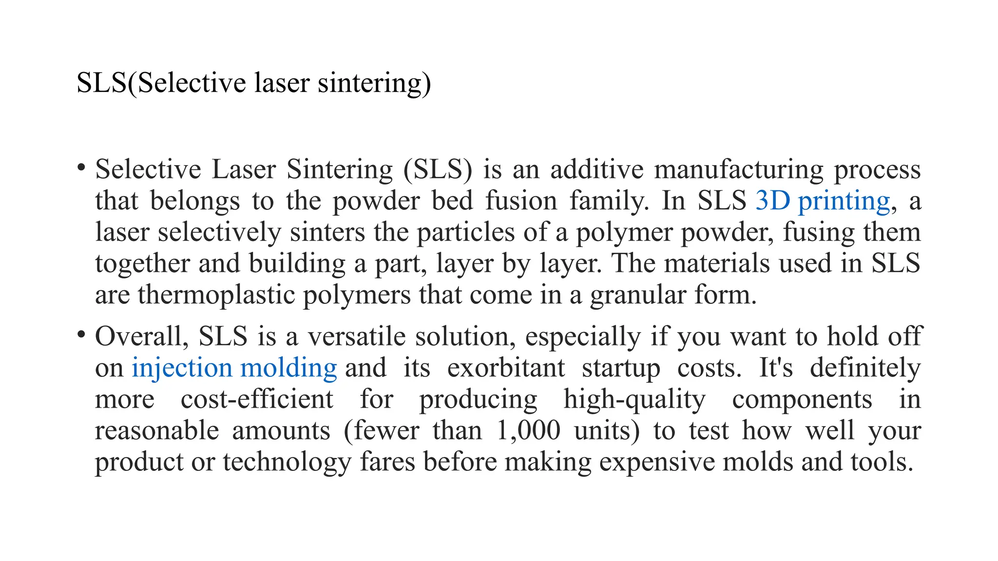
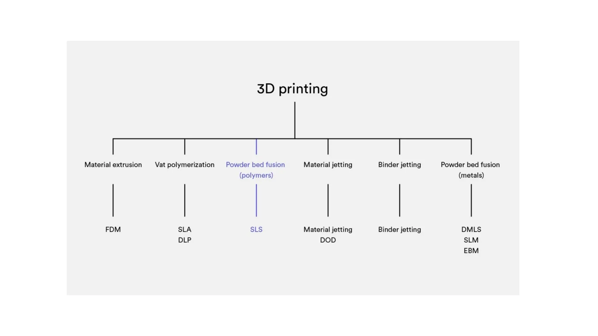
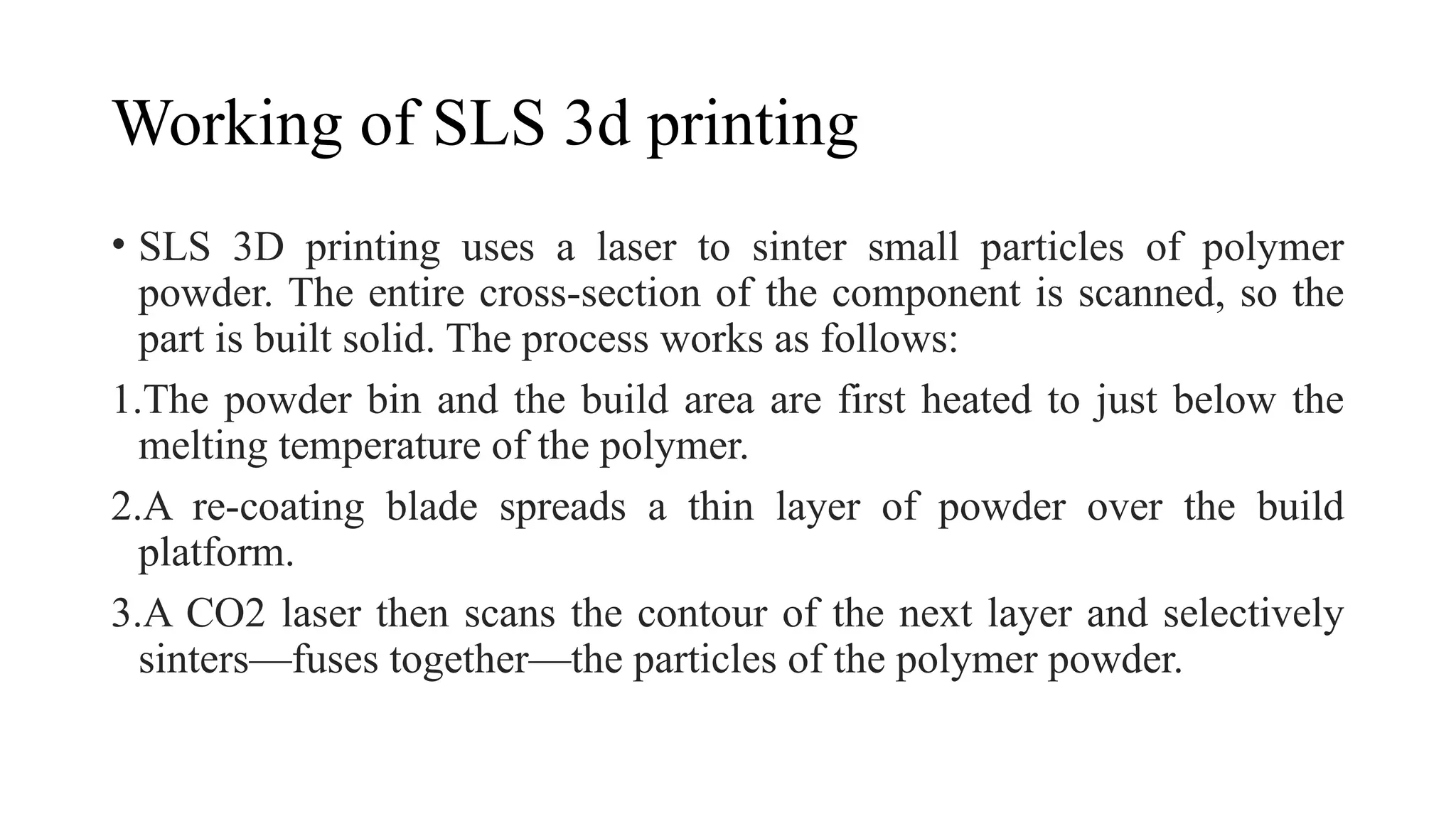
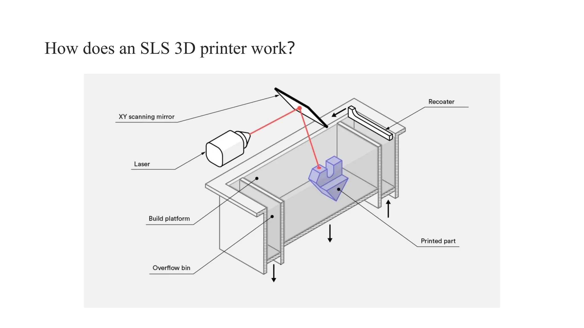
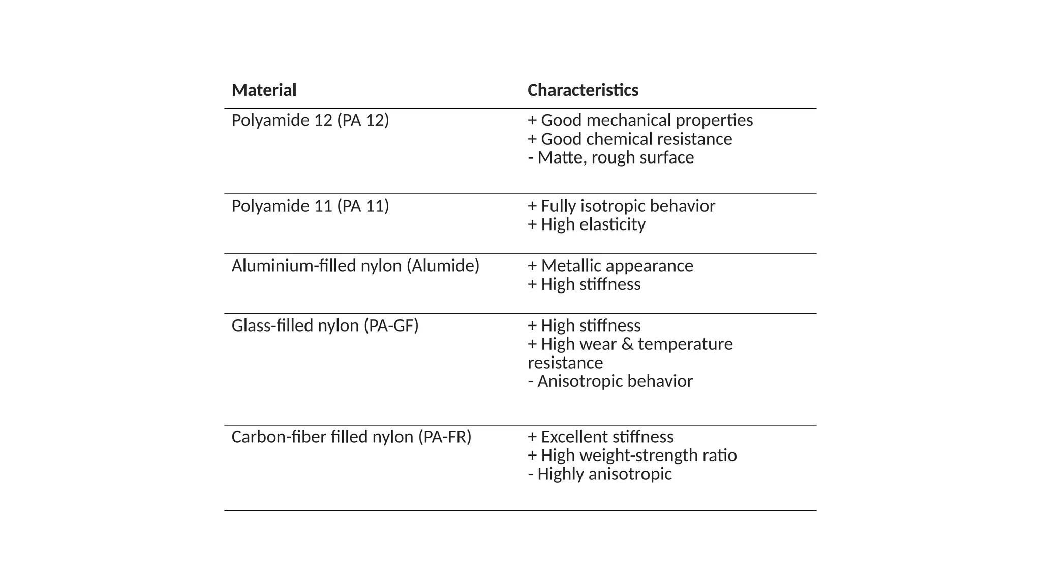
Unit 5
Powder based systems
SLS(Selective laser sintering)
• Selective Laser Sintering (SLS) is an additive manufacturing process
that belongs to the powder bed fusion family. In SLS 3D printing, a
laser selectively sinters the particles of a polymer powder, fusing them
together and building a part, layer by layer. The materials used in SLS
are thermoplastic polymers that come in a granular form.
• Overall, SLS is a versatile solution, especially if you want to hold off
on injection molding and its exorbitant startup costs. It's definitely
more cost-efficient for producing high-quality components in
reasonable amounts (fewer than 1,000 units) to test how well your
product or technology fares before making expensive molds and tools.
Working of SLS 3d printing
• SLS 3D printing uses a laser to sinter small particles of polymer
powder. The entire cross-section of the component is scanned, so the
part is built solid. The process works as follows:
1.The powder bin and the build area are first heated to just below the
melting temperature of the polymer.
2.A re-coating blade spreads a thin layer of powder over the build
platform.
3.A CO2 laser then scans the contour of the next layer and selectively
sinters—fuses together—the particles of the polymer powder.
4. When a layer is complete, the build platform moves downwards and
the blade re-coats the surface. The process then repeats until the whole
part is complete.
5. After printing, the parts are fully encapsulated in unsintered powder.
The powder bin must cool before the parts can be unpacked, which can
take a considerable amount of time—sometimes up to 12 hours.
6. The parts are then cleaned with compressed air or another blasting
media, then they are ready to use or further post-process.
SLS
• https://youtu.be/k7JBYULNQJ8
• SLS is a great solution for the rapid prototyping of functional
polymers because it offers a very high degree of design freedom and
high accuracy. And unlike FDM or SLA 3D printing techniques, it
produces parts with consistent mechanical properties. This means it
can be leveraged to produce parts that are very close to end-use part
quality, so you can rely on the technology for concept to trial models.
Can you use SLS 3D printing for low-production runs?
• Its versatility makes SLS 3D printing an ideal alternative to injection
molding for low-production runs. SLS can be used to manufacture
parts with complex shapes and geometries, and with a wide variety of
finishes and lead times.
How does an SLS 3D printer work?
• For use of an SLS 3D printer, almost all process parameters are preset
by the machine manufacturer. The default layer height used is 100–
120 microns.
• A key advantage of SLS 3D printing is that it needs no support
structures. The unsintered powder provides the part with all the
necessary support. For this reason, SLS can be used to create free-
form geometries that are impossible to manufacture with any other
method.
• Taking advantage of the whole build volume is very important when
printing with SLS, especially for small-batch productions. This is
because laser scanning occurs very rapidly, so it’s actually the re-
coating step that determines the total processing time. The machine
will have to cycle through the same number of layers regardless of the
number of parts. Bin packing may affect lead times of small orders, as
operators may wait until a bin is filled before starting a print task.
Layer adhesion
• The bond strength between layers in SLS 3D printing is excellent.
This means that SLS-printed parts have almost isotropic mechanical
properties.
• The mechanical properties of SLS specimens printed using standard
polyamide powder (PA 12 or Nylon 12)—the most commonly used
material in SLS—are shown in the next table and compared to the
properties of bulk nylon.
X-Y direction Z direction Bulk PA12
Tensile Strength 48 MPa 42 MPa 35–55 MPa
Tensile Modulus 1650 MPa 1650 MPa 1270–2600 MPa
Elongation at break 18% 4% 120–300%
SLS parts have excellent tensile strength and modulus, comparable to the bulk
material, but are more brittle—their elongation at break is much lower. This is
due to the internal porosity of the final part.
Shrinkage and warping
• SLS parts are susceptible to shrinkage and warping. As the newly sintered
layer cools, its dimensions decrease and internal stresses build up, pulling
the underlying layer upwards.
• It's important to note that 3 to 3.5% shrinkage is typical in SLS, but
machine operators take this into account during the build preparation phase
and adjust the size of the design accordingly.
• Large flat surfaces are the most likely to warp. The issue can be mitigated
somewhat by orientating the part vertically in the build platform, but the
best practice is to reduce its volume by minimizing the thickness of the flat
areas and by introducing cutouts to the design. This strategy will also
reduce the overall cost of the part, as less material is used
oversintering
• Oversintering occurs when radiant heat fuses unsintered powder
around a feature. This can result in a loss of detail in small features,
such as slots and holes. As a rule of thumb, slots wider than 0.8mm
and holes with diameters larger than 2mm can be printed in SLS
without fear of oversintering.
Powder removal
• Since SLS requires no support material, parts with hollow sections can be printed easily
and accurately.
• Hollow sections reduce the weight and cost of a part, as less material is used. Escape
holes are needed to remove the unsintered powder from the inner sections of the
component. We recommend adding at least two escape holes to your design, with a
minimum diameter of 5mm.
• If a high degree of stiffness is required, parts must be printed fully solid. An
alternative is to make a hollow design omitting the escape holes. In this way, any
tightly packed powder will be trapped in the part, increasing its mass and providing
some additional support against mechanical loads, without an effect on the build
time.
• An internal honeycomb lattice structure can be added to the hollowed interior
(similar to the infill patterns used in FDM) to further increase the stiffness of the
component. Hollowing a part this way may also reduce warping.
What are the characteristics of SLS 3D printing?
Selective Laser Sintering (SLS)
Materials Thermoplastics (usually nylon)
Dimensional accuracy ± 0.3% (lower limit of ± 0.3
mm)
Typical build size 300 x 300 x 300mm (up to 750
x 550 x 550mm)
Common layer thickness 100–120 µm
Support Not required
The main characteristics of SLA are summarized in the table below:
What are the characteristics of SLS 3D printing
What materials are used for SLS printing?
• The most widely used SLS material is Polyamide 12 (PA 12), also
known as Nylon 12. The price per kilogram of PA 12 powder is around
$50–$60. Other engineering plastics such as PA 11 and PEEKare also
available, but these are not as widely used.
• Polyamide powder can be filled with various additives to improve the
mechanical and thermal behavior of the produced SLS part. Examples
of additives include carbon fibers, glass fibers or aluminum. Materials
filled with additives are usually more brittle and can have highly
anisotropic behavior.
Material Characteristics
Polyamide 12 (PA 12) + Good mechanical properties
+ Good chemical resistance
- Matte, rough surface
Polyamide 11 (PA 11) + Fully isotropic behavior
+ High elasticity
Aluminium-filled nylon (Alumide) + Metallic appearance
+ High stiffness
Glass-filled nylon (PA-GF) + High stiffness
+ High wear & temperature
resistance
- Anisotropic behavior
Carbon-fiber filled nylon (PA-FR) + Excellent stiffness
+ High weight-strength ratio
- Highly anisotropic
What are the options for SLS post-processing?
• SLS 3D printing produces parts with a powdery, grainy surface finish
that can be easily stained. The appearance of SLS printed parts can be
improved to a very high standard using various post-processing
methods, such as media polishing, dyeing, spray painting and
lacquering. Their functionality can also be enhanced by applying a
watertight coating or metal plating
Advantages of SLS
• SLS parts have good, isotropic mechanical properties, making them
ideal for functional parts and prototypes.
• SLS requires no support, so designs with complex geometries can be
easily produced.
• The manufacturing capabilities of SLS are excellent for small to
medium batch production.
• All remaining unsintered powder is collected and can be reused.
Dis-advantages of SLS
• Only industrial SLS systems are currently widely available, so lead
times are longer than other 3D printing technologies, such as FDM
and SLA.
• SLS parts have a grainy surface finish and internal porosity that may
require post-processing if a smooth surface or water tightness is
required.
• Large flat surfaces and small holes cannot be printed accurately with
SLS, as they are susceptible to warping and oversintering.
Applications of SLS
General
• Functional Proof of Concept Models
• Design Evaluation Models (Form & Fit)
• Engineering Design Verification
• Product Performance and Testing
• Wind-Tunnel Test Models
Rapid Manufacturing
• Aerospace hardware
• Medical and healthcare
• Electronics; packaging, connectors
• Homeland security
• Military hardware
Tooling and Patterns
• Jigs, fixtures and tools
• Investment Casting Patterns
Production
• Short run end-use components
• Complex plastic parts
• Part consolidation exercises
LENS(Laser engineered net shaping)
• Laser-engineered net shaping (LENS) technology was jointly conceptualized by
Sandia National Laboratories and Pratt & Whitney and then licensed to Optomec,
Inc., during 1997 (US Patent 6046426, 2000). A schematic of this process is
shown in Fig. Unlike in SLM, which has a powder bed, the component is
manufactured using the LENS technique by supplying a powder through nozzle
injection and irradiating a laser beam with high energy density to melt and
deposit over a build base-plate in a layer-by-layer scheme. After deposition of
each layer the build platform moves down in a controlled manner. This process
repeats until an expected component is realized. Although the LENS technique
was basically developed to produce complex geometrical components, it also has
an ideal for repair and refurbishment of damaged components and structures. It
should be noted that, the LENS has few concerns such as need for
postprocessing, poor component surface finish, and distortion in the components
due to residual stresses.
Detailed explanation
• https://www.google.co.in/url?sa=t&rct=j&q=&esrc=s&source=video&
cd=&cad=rja&uact=8&ved=2ahUKEwjhm-XP2ZiEAxXv2DgGHbTyC-IQt
wJ6BAgNEAI&url=https%3A%2F%2Fwww.youtube.com%2Fwatch%3F
v%3DwF0OzXbADPQ&usg=AOvVaw0egEHgMeWpVjOUznYk49f8&opi=
89978449
EBM( Electron beam melting)
• Electron Beam Melting (EBM) is part of the powder bed fusion family. Unlike
Laser Powder Bed Fusion(LPBF), it uses, as its name suggests, an electron beam to
fuse metal particles and create, layer by layer, the desired part. Marketed by the
Swedish company Arcam in 2002, this process enables the creation of complex and
highly resistant structures. Note that Arcam was acquired by GE Additive in 2016
and is the only one to market machines based on this process as of today.
• The main difference with LPBF technology is therefore the heat source used. Here,
EBM technology uses an electron beam produced by an electron gun. The latter
extracts the electrons from a tungsten filament under vacuum and projects them in
an accelerated way on the layer of metallic powder deposited on the building plate
of the 3D printer. These electrons will then be able to selectively fuse the powder
and thus produce the part.
The Electron Beam Melting process
• Everything starts with the 3D modeling of the part you wish to create. You
can model it using CAD software, obtain it by 3D scanning or download a
model of your choice. The 3D model is then sent to a slicing software, also
called slicer, which will cut it according to the successive physical layers of
deposited material. The slicer will then send all this information directly to
the 3D printer, which can then start its manufacturing process. The metal
powder can be loaded into the tank within the machine. It will be deposited
in thin layers that will be preheated before being fused by the electron
beam. In particular, this step provides more support to the cantilever areas
of the part being 3D printed. The machine then repeats these steps as many
times as necessary to obtain the entire part.
• Once the manufacturing process is complete, the operator removes the part
from the machine and ejects the unmelted powder with a blowgun or brush.
Following this, it’s possible to remove the printing supports (if any have been
used) and to detach the part from the build plate. The post-printing steps can
include machining of surfaces in contact with other parts, polishing, etc. In
some cases, it may be necessary to heat the part in an oven for several hours to
release the stresses induced by the manufacturing process.
• Note that all manufacturing must take place under vacuum to properly operate
the electron beam. This also prevents the powder from oxidizing when heated.
At the end of the production process, a large part of the unmelted powder can
be reused almost directly. It is easy to understand the interest that this
represents for manufacturers, particularly in the aeronautics sector where it
often happens that only 20% of the purchased material is actually used to
produce the final part, the rest being removed by machining and sent for
recycling.
Materials and applications
• https://youtu.be/M_qSnjKN7f8
• As the process is based on the principle of electrical charges, the materials used must be
conductive. Without this, no interaction can occur between the electron beam and the
powder. The manufacture of polymer or ceramic parts is therefore technically impossible
with an electron beam and only metals can be used. Today, titanium and chromium-cobalt
alloys are mainly used – Arcam has restricted the range of compatible materials. In fact,
to be allowed to use or test another material, users must undertake paid training and obtain
an authorization to use the machine as they see fit.
• EBM technology is mainly used in aeronautics and medical applications, particularly for
implant design. Titanium alloys are particularly interesting because of their biocompatible
properties and mechanical properties, they can offer lightness and strength. The
technology is widely used to design turbine blades, for example, or engine parts. Electron
Beam Melting technology will create parts faster than LPBF technology, but the process is
less accurate and the finish will be of lower quality because the powder is more granular.
Laser or Electron Beam?
• The question is regularly asked by manufacturers who are interested in metal 3D printing. The answer
depends mainly on what applications you are interested in, because each process comes with benefits
and limitations.
Strengths
• Manufacturing speed. The electron beam can separate to heat the powder in several places
simultaneously, which significantly speeds up production. On the other hand, a laser must scan the
surface point by point.
• Pre-heating the power before it melts limits the deformations and thus reduces the need for
reinforcements and supports during manufacturing.
Weaknesses
• Precision. At the powder level, the electron beam is a little wider than the laser beam, which reduces
the accuracy.
• The size of the parts that can be manufactured. Arcam’s largest build volume (on the Q20 machine)
represents a diameter of 350 mm for a height of 380 mm. On the other hand, laser machines (such as
the X-Line of Concept Laser) offer manufacturing volumes at least twice as high.
Advantages
• The main advantage of EBM is the manufacturing speed it affords due
to the high energy density. Production is further sped up by the
electron beam’s capacity to heat several areas of powder
simultaneously. By contrast, a laser-based additive manufacturing
technique, such as selective laser melting (SLM) is slower as it scans
the surface one point at a time, although this does lead to smoother
and more accurate parts.
• Pre-heating the powder before melting using EBM limits deformations
and reduces the need for supports or reinforcements that have to be
removed after manufacturing.
Disadvantages
• Because electron beams are slightly wider than laser beams, EBM is
less accurate than an additive process like SLM.
• Much of the available technology limits the size of the parts that can
be created with EBM, whereas laser machines can manufacture parts
of over twice their height.
• EBM printers require skilled technicians to operate.
Materials and applications
• The materials need to be conductive in order for the electron beam to
affect them, this means that electron beams cannot be used with
ceramics or polymers. The main metals that are used for EBM are
titanium and chromium cobalt alloys.
• Applications for EBM include within the aerospace and medical
industries. This is, for example, because titanium is biocompatible and
has desirable mechanical properties. While EBM can produce parts
quickly, the lower accuracy and granular finish means it is not suitable
for all applications. However, despite the drawbacks, it used to quickly
print parts for aerospace, automotive, defence and medical purposes.

the applications of bio printing using additive manufacturing

  • 1.
  • 2.
    SLS(Selective laser sintering) •Selective Laser Sintering (SLS) is an additive manufacturing process that belongs to the powder bed fusion family. In SLS 3D printing, a laser selectively sinters the particles of a polymer powder, fusing them together and building a part, layer by layer. The materials used in SLS are thermoplastic polymers that come in a granular form. • Overall, SLS is a versatile solution, especially if you want to hold off on injection molding and its exorbitant startup costs. It's definitely more cost-efficient for producing high-quality components in reasonable amounts (fewer than 1,000 units) to test how well your product or technology fares before making expensive molds and tools.
  • 4.
    Working of SLS3d printing • SLS 3D printing uses a laser to sinter small particles of polymer powder. The entire cross-section of the component is scanned, so the part is built solid. The process works as follows: 1.The powder bin and the build area are first heated to just below the melting temperature of the polymer. 2.A re-coating blade spreads a thin layer of powder over the build platform. 3.A CO2 laser then scans the contour of the next layer and selectively sinters—fuses together—the particles of the polymer powder.
  • 5.
    4. When alayer is complete, the build platform moves downwards and the blade re-coats the surface. The process then repeats until the whole part is complete. 5. After printing, the parts are fully encapsulated in unsintered powder. The powder bin must cool before the parts can be unpacked, which can take a considerable amount of time—sometimes up to 12 hours. 6. The parts are then cleaned with compressed air or another blasting media, then they are ready to use or further post-process.
  • 6.
    SLS • https://youtu.be/k7JBYULNQJ8 • SLSis a great solution for the rapid prototyping of functional polymers because it offers a very high degree of design freedom and high accuracy. And unlike FDM or SLA 3D printing techniques, it produces parts with consistent mechanical properties. This means it can be leveraged to produce parts that are very close to end-use part quality, so you can rely on the technology for concept to trial models.
  • 7.
    Can you useSLS 3D printing for low-production runs? • Its versatility makes SLS 3D printing an ideal alternative to injection molding for low-production runs. SLS can be used to manufacture parts with complex shapes and geometries, and with a wide variety of finishes and lead times.
  • 8.
    How does anSLS 3D printer work?
  • 9.
    • For useof an SLS 3D printer, almost all process parameters are preset by the machine manufacturer. The default layer height used is 100– 120 microns. • A key advantage of SLS 3D printing is that it needs no support structures. The unsintered powder provides the part with all the necessary support. For this reason, SLS can be used to create free- form geometries that are impossible to manufacture with any other method. • Taking advantage of the whole build volume is very important when printing with SLS, especially for small-batch productions. This is because laser scanning occurs very rapidly, so it’s actually the re- coating step that determines the total processing time. The machine will have to cycle through the same number of layers regardless of the number of parts. Bin packing may affect lead times of small orders, as operators may wait until a bin is filled before starting a print task.
  • 10.
    Layer adhesion • Thebond strength between layers in SLS 3D printing is excellent. This means that SLS-printed parts have almost isotropic mechanical properties. • The mechanical properties of SLS specimens printed using standard polyamide powder (PA 12 or Nylon 12)—the most commonly used material in SLS—are shown in the next table and compared to the properties of bulk nylon.
  • 11.
    X-Y direction Zdirection Bulk PA12 Tensile Strength 48 MPa 42 MPa 35–55 MPa Tensile Modulus 1650 MPa 1650 MPa 1270–2600 MPa Elongation at break 18% 4% 120–300% SLS parts have excellent tensile strength and modulus, comparable to the bulk material, but are more brittle—their elongation at break is much lower. This is due to the internal porosity of the final part.
  • 12.
    Shrinkage and warping •SLS parts are susceptible to shrinkage and warping. As the newly sintered layer cools, its dimensions decrease and internal stresses build up, pulling the underlying layer upwards. • It's important to note that 3 to 3.5% shrinkage is typical in SLS, but machine operators take this into account during the build preparation phase and adjust the size of the design accordingly. • Large flat surfaces are the most likely to warp. The issue can be mitigated somewhat by orientating the part vertically in the build platform, but the best practice is to reduce its volume by minimizing the thickness of the flat areas and by introducing cutouts to the design. This strategy will also reduce the overall cost of the part, as less material is used
  • 13.
    oversintering • Oversintering occurswhen radiant heat fuses unsintered powder around a feature. This can result in a loss of detail in small features, such as slots and holes. As a rule of thumb, slots wider than 0.8mm and holes with diameters larger than 2mm can be printed in SLS without fear of oversintering.
  • 14.
    Powder removal • SinceSLS requires no support material, parts with hollow sections can be printed easily and accurately. • Hollow sections reduce the weight and cost of a part, as less material is used. Escape holes are needed to remove the unsintered powder from the inner sections of the component. We recommend adding at least two escape holes to your design, with a minimum diameter of 5mm. • If a high degree of stiffness is required, parts must be printed fully solid. An alternative is to make a hollow design omitting the escape holes. In this way, any tightly packed powder will be trapped in the part, increasing its mass and providing some additional support against mechanical loads, without an effect on the build time. • An internal honeycomb lattice structure can be added to the hollowed interior (similar to the infill patterns used in FDM) to further increase the stiffness of the component. Hollowing a part this way may also reduce warping.
  • 15.
    What are thecharacteristics of SLS 3D printing? Selective Laser Sintering (SLS) Materials Thermoplastics (usually nylon) Dimensional accuracy ± 0.3% (lower limit of ± 0.3 mm) Typical build size 300 x 300 x 300mm (up to 750 x 550 x 550mm) Common layer thickness 100–120 µm Support Not required The main characteristics of SLA are summarized in the table below: What are the characteristics of SLS 3D printing
  • 16.
    What materials areused for SLS printing? • The most widely used SLS material is Polyamide 12 (PA 12), also known as Nylon 12. The price per kilogram of PA 12 powder is around $50–$60. Other engineering plastics such as PA 11 and PEEKare also available, but these are not as widely used. • Polyamide powder can be filled with various additives to improve the mechanical and thermal behavior of the produced SLS part. Examples of additives include carbon fibers, glass fibers or aluminum. Materials filled with additives are usually more brittle and can have highly anisotropic behavior.
  • 17.
    Material Characteristics Polyamide 12(PA 12) + Good mechanical properties + Good chemical resistance - Matte, rough surface Polyamide 11 (PA 11) + Fully isotropic behavior + High elasticity Aluminium-filled nylon (Alumide) + Metallic appearance + High stiffness Glass-filled nylon (PA-GF) + High stiffness + High wear & temperature resistance - Anisotropic behavior Carbon-fiber filled nylon (PA-FR) + Excellent stiffness + High weight-strength ratio - Highly anisotropic
  • 18.
    What are theoptions for SLS post-processing? • SLS 3D printing produces parts with a powdery, grainy surface finish that can be easily stained. The appearance of SLS printed parts can be improved to a very high standard using various post-processing methods, such as media polishing, dyeing, spray painting and lacquering. Their functionality can also be enhanced by applying a watertight coating or metal plating
  • 19.
    Advantages of SLS •SLS parts have good, isotropic mechanical properties, making them ideal for functional parts and prototypes. • SLS requires no support, so designs with complex geometries can be easily produced. • The manufacturing capabilities of SLS are excellent for small to medium batch production. • All remaining unsintered powder is collected and can be reused.
  • 20.
    Dis-advantages of SLS •Only industrial SLS systems are currently widely available, so lead times are longer than other 3D printing technologies, such as FDM and SLA. • SLS parts have a grainy surface finish and internal porosity that may require post-processing if a smooth surface or water tightness is required. • Large flat surfaces and small holes cannot be printed accurately with SLS, as they are susceptible to warping and oversintering.
  • 21.
    Applications of SLS General •Functional Proof of Concept Models • Design Evaluation Models (Form & Fit) • Engineering Design Verification • Product Performance and Testing • Wind-Tunnel Test Models Rapid Manufacturing • Aerospace hardware • Medical and healthcare • Electronics; packaging, connectors • Homeland security • Military hardware
  • 22.
    Tooling and Patterns •Jigs, fixtures and tools • Investment Casting Patterns Production • Short run end-use components • Complex plastic parts • Part consolidation exercises
  • 23.
    LENS(Laser engineered netshaping) • Laser-engineered net shaping (LENS) technology was jointly conceptualized by Sandia National Laboratories and Pratt & Whitney and then licensed to Optomec, Inc., during 1997 (US Patent 6046426, 2000). A schematic of this process is shown in Fig. Unlike in SLM, which has a powder bed, the component is manufactured using the LENS technique by supplying a powder through nozzle injection and irradiating a laser beam with high energy density to melt and deposit over a build base-plate in a layer-by-layer scheme. After deposition of each layer the build platform moves down in a controlled manner. This process repeats until an expected component is realized. Although the LENS technique was basically developed to produce complex geometrical components, it also has an ideal for repair and refurbishment of damaged components and structures. It should be noted that, the LENS has few concerns such as need for postprocessing, poor component surface finish, and distortion in the components due to residual stresses.
  • 25.
  • 26.
    EBM( Electron beammelting) • Electron Beam Melting (EBM) is part of the powder bed fusion family. Unlike Laser Powder Bed Fusion(LPBF), it uses, as its name suggests, an electron beam to fuse metal particles and create, layer by layer, the desired part. Marketed by the Swedish company Arcam in 2002, this process enables the creation of complex and highly resistant structures. Note that Arcam was acquired by GE Additive in 2016 and is the only one to market machines based on this process as of today. • The main difference with LPBF technology is therefore the heat source used. Here, EBM technology uses an electron beam produced by an electron gun. The latter extracts the electrons from a tungsten filament under vacuum and projects them in an accelerated way on the layer of metallic powder deposited on the building plate of the 3D printer. These electrons will then be able to selectively fuse the powder and thus produce the part.
  • 27.
    The Electron BeamMelting process • Everything starts with the 3D modeling of the part you wish to create. You can model it using CAD software, obtain it by 3D scanning or download a model of your choice. The 3D model is then sent to a slicing software, also called slicer, which will cut it according to the successive physical layers of deposited material. The slicer will then send all this information directly to the 3D printer, which can then start its manufacturing process. The metal powder can be loaded into the tank within the machine. It will be deposited in thin layers that will be preheated before being fused by the electron beam. In particular, this step provides more support to the cantilever areas of the part being 3D printed. The machine then repeats these steps as many times as necessary to obtain the entire part.
  • 28.
    • Once themanufacturing process is complete, the operator removes the part from the machine and ejects the unmelted powder with a blowgun or brush. Following this, it’s possible to remove the printing supports (if any have been used) and to detach the part from the build plate. The post-printing steps can include machining of surfaces in contact with other parts, polishing, etc. In some cases, it may be necessary to heat the part in an oven for several hours to release the stresses induced by the manufacturing process. • Note that all manufacturing must take place under vacuum to properly operate the electron beam. This also prevents the powder from oxidizing when heated. At the end of the production process, a large part of the unmelted powder can be reused almost directly. It is easy to understand the interest that this represents for manufacturers, particularly in the aeronautics sector where it often happens that only 20% of the purchased material is actually used to produce the final part, the rest being removed by machining and sent for recycling.
  • 29.
    Materials and applications •https://youtu.be/M_qSnjKN7f8 • As the process is based on the principle of electrical charges, the materials used must be conductive. Without this, no interaction can occur between the electron beam and the powder. The manufacture of polymer or ceramic parts is therefore technically impossible with an electron beam and only metals can be used. Today, titanium and chromium-cobalt alloys are mainly used – Arcam has restricted the range of compatible materials. In fact, to be allowed to use or test another material, users must undertake paid training and obtain an authorization to use the machine as they see fit. • EBM technology is mainly used in aeronautics and medical applications, particularly for implant design. Titanium alloys are particularly interesting because of their biocompatible properties and mechanical properties, they can offer lightness and strength. The technology is widely used to design turbine blades, for example, or engine parts. Electron Beam Melting technology will create parts faster than LPBF technology, but the process is less accurate and the finish will be of lower quality because the powder is more granular.
  • 30.
    Laser or ElectronBeam? • The question is regularly asked by manufacturers who are interested in metal 3D printing. The answer depends mainly on what applications you are interested in, because each process comes with benefits and limitations. Strengths • Manufacturing speed. The electron beam can separate to heat the powder in several places simultaneously, which significantly speeds up production. On the other hand, a laser must scan the surface point by point. • Pre-heating the power before it melts limits the deformations and thus reduces the need for reinforcements and supports during manufacturing. Weaknesses • Precision. At the powder level, the electron beam is a little wider than the laser beam, which reduces the accuracy. • The size of the parts that can be manufactured. Arcam’s largest build volume (on the Q20 machine) represents a diameter of 350 mm for a height of 380 mm. On the other hand, laser machines (such as the X-Line of Concept Laser) offer manufacturing volumes at least twice as high.
  • 31.
    Advantages • The mainadvantage of EBM is the manufacturing speed it affords due to the high energy density. Production is further sped up by the electron beam’s capacity to heat several areas of powder simultaneously. By contrast, a laser-based additive manufacturing technique, such as selective laser melting (SLM) is slower as it scans the surface one point at a time, although this does lead to smoother and more accurate parts. • Pre-heating the powder before melting using EBM limits deformations and reduces the need for supports or reinforcements that have to be removed after manufacturing.
  • 32.
    Disadvantages • Because electronbeams are slightly wider than laser beams, EBM is less accurate than an additive process like SLM. • Much of the available technology limits the size of the parts that can be created with EBM, whereas laser machines can manufacture parts of over twice their height. • EBM printers require skilled technicians to operate.
  • 33.
    Materials and applications •The materials need to be conductive in order for the electron beam to affect them, this means that electron beams cannot be used with ceramics or polymers. The main metals that are used for EBM are titanium and chromium cobalt alloys. • Applications for EBM include within the aerospace and medical industries. This is, for example, because titanium is biocompatible and has desirable mechanical properties. While EBM can produce parts quickly, the lower accuracy and granular finish means it is not suitable for all applications. However, despite the drawbacks, it used to quickly print parts for aerospace, automotive, defence and medical purposes.