This document provides an agenda and overview for a 2016 Meter School on test switches and accessories. It discusses test switch specifications, configurations, materials, and safety considerations. The key points are:
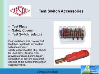
- Test switches allow inserting instruments into current transformer circuits safely to test meters, without opening the live secondary circuit.
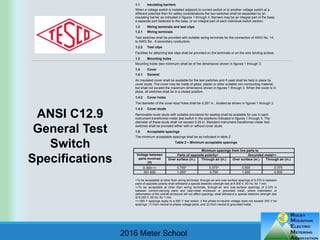
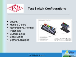
- Specifications cover ratings, materials, barriers between switches, terminals, and minimum spacings. Configurations vary layout, handle colors, and potentials.
- Accessories include test plugs, safety covers, and isolators to allow testing while maintaining safety.
- Proper use and safety procedures are important as open current transformer circuits can generate high voltages, creating electrical and insulation breakdown hazards.