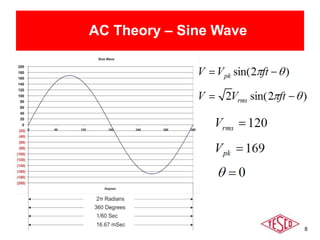
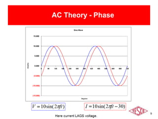
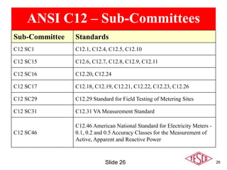
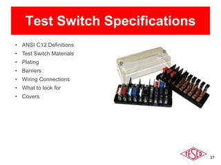
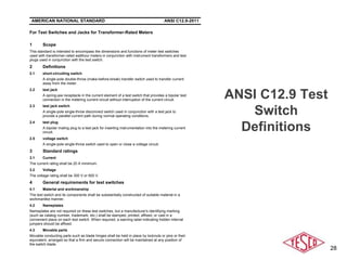
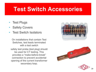
1
10/02/2012 Slide 1
Learning the Language
(Meter Testing 101)
Prepared by Tom Lawton, TESCO
For Mid-South Electric Metering Association Meter School
Monday, May 6, 2019
3:00 p.m., Group 1
2
Our Goal Today
• To give you enough background to be able to
understand the basic concepts being introduced
or to refresh you on the basic concepts about to
be introduced and in both cases give you some
level of background to help better understand
each of them.
3
Learning the Language
Over the next three days you will have a series of
Metering 101 presentations. These will include
classes on;
– Basic Electricity
– Form Numbers
– Wiring Diagrams
– AC Circuits
– Self Contained Metering
– Demand Metering
– Transformer Rated Metering
4
Basic Electricity
Direct Current (DC) – an electric current
that flows in one direction.(IEEE100)
Alternating Current (AC) – an electric
current that reverses direction at regularly
recurring intervals of time. (IEEE100)
5
War of the Currents
Thomas Edison George Westinghouse Nikola Tesla
6
AC Theory - History
• By 1900 AC power systems had won the
battle for power distribution.
– Transformers allowed more efficient
distribution of power over large areas.
– AC motors were cheaper and easier to build.
– AC electric generators were easier to build.
7
AC Circuits
• An AC circuit has three general
characteristics
• Value
• Frequency
• Phase
• In the US, the household value is 120 Volts
with other common voltages being 208, 240,
277 and 480 Volts. The frequency is 60 Hertz
(cycles per second).
8
AC Theory – Sine Wave
9
AC Theory - Phase
Sine Wave
(15.000)
(10.000)
(5.000)
0.000
5.000
10.000
15.000
0 60 120 180 240 300 360 420 480 540 600 660 720
Degrees
Amplitude
10
• Active Power is defined as P = VA
• Power is a rate, i.e. Energy per unit time.
• The Watt is the unit for Power
– 1 Watt = 1000 Joules/sec
• Since the voltage and current at every point in
time for an AC signal is different, we have to
distinguish between instantaneous power and
average power.
• Generally when we say “power” we mean
average power.
Slide 10
AC Theory – Active Power
11
AC Theory - Energy
• Energy is power integrated over a period of time.
• The units of Energy are:
– Watt-Hour (abbreviated Wh)
– Kilowatt-Hour (abbreviated kWh)
• A Wh is the total energy consumed when a load
draws one Watt for one hour.
Slide 11
12
Harmonics
Curse of the Modern World
• Every thing discussed so far was based on
“Linear” loads.
– For linear loads the current is always a simple
sine wave. Everything we have discussed is
true.
• For nearly a century after AC power was in
use ALL loads were linear.
• Today, many loads are NON-LINEAR.
Slide 12
13
Harmonic Load Waveforms
Slide 13
14
Active vs. Apparent Power
Apparent Power - S
• The apparent power is the power supplied to the
electric circuit - typical from a power supplier to
the grid - to cover the real and reactive power
consumption in the loads. Measured in VA.
Active Power - P
• Active - or real or true - power do the actual work
in the load. Active power is measured in watts
(W) and is the power consumed by electrical
resistance. Measured in Watts
Slide 14
15
AC Theory – Phasors
Slide 15
CURRENTVOLTAGE
A
B
C
Va 0°
I a 0°
Vb 120°
I b 120°
Vc 240°
I c 240°
THE VECTOR
DIAGRAM
An easier way
to view AC
data
16
Self Contained Metering
• Typically found in residential
metering
• Meters are capable of handling
the direct incoming amperage
• Meter is connected directly to
the load being measured
• Meter is part of the circuit
• When the meter is removed
from the socket, power to the
customer is interrupted
17
Transformer Rated Metering
• Meter measures scaled down
representation of the load.
• Scaling is accomplished by the use
of external current transformers
(CTs) and sometimes voltage
transformers or PTs).
• The meter is NOT part of the circuit
• When the meter is removed from
the socket, power to the customer
is not effected.
18
Pre-Wired Transformer Rated Enclosures
• Cover Types
• Wiring
• Sockets
19
The Basic Components
20
Typical Connections
Typical Connections for Common
Transformer (Instrument)
Rated Meter Forms
21
ANSI
• American National Standard Institute, Inc.
• Not a government agency
• Standards do not have force of Law
• All compliance is voluntary
• ANSI doesn’t actually generate any standards
• Each standard is controlled by an industry
organization as the “secretariat”
• For C12 NEMA (National Electrical Manufacturer’s
Association) is the secretariat
• Paul Orr has been the NEMA’s secretary assigned to
C12 for over ten years providing continuity to the
process
Slide 21
22
• American National Standard Institute, Inc.
• NEMA organizes committees to propose and
review standards
• Standards are republished approximately every 5
years
• Standards codify consensus approaches in
common practice
• Generally, they do not break new ground or deal
in controversial issues
• This is changing. Can’t avoid issues any longer.
Slide 22
ANSI
23
ANSI C12
• C12 Main Committee
• General makeup has expanded slightly over last
few years
• 34 voting members with representation from three
groups:
• 12 - Manufacturers: Meter, Socket, Test Equipment, etc.
• 13 - Users: Utilities
• 9 - General Interest: PUC, UL, IEEE, Consultants, etc.
• Meets twice a year in conjunction with EEI/AEIC
Meter conference.
Slide 23
24
• C12 Main Committee
• Has final approval for all activities on any C12 family
standard
• Establishes Subcommittees (SC) and Working
Groups (WG) to address various standards and
issues
• Sub committees and Working Groups also meet twice
a year in conjunction with EEI Transmission,
Distribution and Metering Conference and also hold
regular or ad hoc conference calls throughout the
year as members put together drafts and other
technical material for consideration at the next face to
face meeting.
Slide 24
ANSI
25
• C12 Subcommittees
• Various subcommittees have been organized to
review specific standards
• This is where the work is really done
• Each operates slightly differently
• Each meets on a schedule of its own choosing
• Most meet at EEI Biannual Transmission,
Distribution and Metering Meetings
• Communication WG meets more often and longer
• Various subgroups meet frequently by
teleconference
Slide 25
ANSI
26
ANSI C12 – Sub-Committees
Sub-Committee Standards
C12 SC1 C12.1, C12.4, C12.5, C12.10
C12 SC15 C12.6, C12.7, C12.8, C12.9, C12.11
C12 SC16 C12.20, C12.24
C12 SC17 C12.18, C12.19, C12.21, C12.22, C12.23, C12.26
C12 SC29 C12.29 Standard for Field Testing of Metering Sites
C12 SC31 C12.31 VA Measurement Standard
C12 SC46
C12.46 American National Standard for Electricity Meters -
0.1, 0.2 and 0.5 Accuracy Classes for the Measurement of
Active, Apparent and Reactive Power
Slide 26
27
Test Switch Specifications
• ANSI C12 Definitions
• Test Switch Materials
• Plating
• Barriers
• Wiring Connections
• What to look for
• Covers
28
For Test Switches and Jacks for Transformer-Rated Meters
1 Scope
This standard is intended to encompass the dimensions and functions of meter test switches
used with transformer-rated watthour meters in conjunction with instrument transformers and test
plugs used in conjunction with the test switch.
2 Definitions
2.1 short-circuiting switch
A single-pole double-throw (make-before-break) transfer switch used to transfer current
away from the meter.
2.2 test jack
A spring-jaw receptacle in the current element of a test switch that provides a bipolar test
connection in the metering current circuit without interruption of the current circuit.
2.3 test jack switch
A single-pole single-throw disconnect switch used in conjunction with a test jack to
provide a parallel current path during normal operating conditions.
2.4 test plug
A bipolar mating plug to a test jack for inserting instrumentation into the metering current
circuit.
2.5 voltage switch
A single-pole single-throw switch used to open or close a voltage circuit.
3 Standard ratings
3.1 Current
The current rating shall be 20 A minimum.
3.2 Voltage
The voltage rating shall be 300 V or 600 V.
4 General requirements for test switches
4.1 Material and workmanship
The test switch and its components shall be substantially constructed of suitable material in a
workmanlike manner.
4.2 Nameplates
Nameplates are not required on these test switches, but a manufacturer's identifying marking
(such as catalog number, trademark, etc.) shall be stamped, printed, affixed, or cast in a
convenient place on each test switch. When required, a warning label indicating hidden internal
jumpers should be affixed.
4.3 Movable parts
Movable conducting parts such as blade hinges shall be held in place by locknuts or pins or their
equivalent, arranged so that a firm and secure connection will be maintained at any position of
the switch blade.
AMERICAN NATIONAL STANDARD ANSI C12.9-2011
ANSI C12.9 Test
Switch
Definitions
29
Test Switch Accessories
• Test Plugs
• Safety Covers
• Test Switch Isolators
On installations that contain Test
Switches, test leads terminated
with a test switch
safety test probe (test plug) should
be used for CT testing. This
provides a “make-before-break”
connection to prevent accidental
opening of the current transformer
secondary loop.
30
ANSI C12.9
Test Jack
Specifications
4.6 Provision for test plugs
Each double-pole short-circuiting current switch shall incorporate a test jack which is designed to
permit the insertion of a test plug. The test-jack switch can be either in the left-hand or the right-
hand position. In order to assure proper mating with the test plug the test jack shall conform to
Figure 4.
D
A
A
C
W
S
X
SECTION A-A
.
.
Y
DETAIL C
SCALE 2:1
Maximum deflection
of switch blades with
probe inserted
Figure 4 – Test switch typical cross section
Table 1 – Test switch dimensions
TEST SWITCH DIMENSIONS
DIMENSION MINIMUM PREFERRED MAXIMUM
S 0.900 1.200 1.250
W 0.125 0.140 0.175
X 0.430 0.500 0.550
D 1.280 1.350 N/A
Y 0.188
31
ANSI C12.9
Test Plug
Specifications
1 General requirements for test plugs
1.1 Materials and workmanship
The test plug shall be constructed with an insulated handle providing an anti-slip gripping area
and a barrier to help prevent the user’s gloved hand from slipping into contact with the test switch.
B
B
L
M
..
.
Ymax /2
R1
SECTION B-B
SCALE 2 : 1
Insertion
Guide
Standard
Wmin
Alternate #1
R
G
T
P
.
Figure 6 – Typical test plug
Notes:
(1) When the insertion guide takes the form of Section B-B Alternate #1, then for a switch
with a slot width Wmin, the switch Jaws shall not be separated by more than Ymax =
0.188” when inserted.
(2) If a positive stop is provided on the probe blade to limit insertion depth of the probe to M
by bottoming out against S of the switch, then L may exceed Lmax provided M < Dmin –
Smax = 0.030”.
Table 3 – Test plug dimensions
TEST PLUG DIMENSIONS
DIMENSION MINIMUM PREFERRED MAXIMUM
L 1.100 1.200 1.260
M 0 0.140 0.175
R 0.090 0.110 0.120
R1 n/a n/a 0.156
T 0.100 0.130 0.156
G 0.040 0.125 0.175
ALERT TO USERS: Prior to adoption of this standard there are known instances of probes and
switches where interferences exist which may not allow all probes and switches to mate or which
may lead to probes shorting to undesired conductors.
32
Ratio of Primary Current to Secondary Current
PHASE A
SOURCE LOAD
400A
400A
400A
5A5A
Calculate Ratio
Fundamentals of Polyphase Field Meter
Testing and Site Verification
33
Current Transformers (CTs)
34
Fundamentals of Polyphase Field Meter
Testing and Site Verification
Functionality with Burden Present on the Secondary Loop
0.3% @ B0.1, B0.2, B0.5
0.0000
1.0000
2.0000
3.0000
4.0000
5.0000
6.0000
0 2 4 6 8
Initial Reading = 5Amps
0.3% x 5A = 0.015A
5A – 0.015 = 4.985A
Burden Reading
0 5.0000
0.1 4.9999
0.2 4.9950
0.5 4.9900
1 4.9800
2 4.9500
4 4.0000
8 0.8000
35
Three Phase Power
Blondel’s Theorem
The theory of polyphase watthour metering was first set forth on a scientific
basis in 1893 by Andre E. Blondel, engineer and mathematician. His theorem
applies to the measurement of real power in a polyphase system of any
number of wires. The theorem is as follows:
- If energy is supplied to any system of conductors
through N wires, the total power in the system is given
by the algebraic sum of the readings of N wattmeters, so
arranged that each of the N wires contains one current
coil, the corresponding voltage coil being connected
between that wire and some common point. If this
common point is on one of the N wires, the
measurement may be made by the use of N-1
wattmeters.
36
Blondel’s Theorem
Condition % V % I Phase A Phase B
non-
Blondel
Imb Imb V φvan I φian V φvbn I φibn
% Err
All balanced 0 0 120 0 100 0 120 180 100 180 0.00%
Unbalanced voltages PF=1 18% 0% 108 0 100 0 132 180 100 180 0.00%
Unbalanced current PF=1 0% 18% 120 0 90 0 120 180 110 180 0.00%
Unbalanced V&I PF=1 5% 18% 117 0 90 0 123 180 110 180 -0.25%
Unbalanced V&I PF=1 8% 18% 110 0 90 0 120 180 110 180 -0.43%
Unbalanced V&I PF=1 8% 50% 110 0 50 0 120 180 100 180 -1.43%
Unbalanced V&I PF=1 18% 40% 108 0 75 0 132 180 125 180 -2.44%
Unbalanced voltages
PF≠1 PFa = PFb
18% 0% 108 0 100 30 132 180 100 210 0.00%
Unbalanced current
PF≠1 PFa = PFb
0% 18% 120 0 90 30 120 180 110 210 0.00%
Unbalanced V&I
PF≠1 PFa = PFb
18% 18% 108 0 90 30 132 180 110 210 -0.99%
Unbalanced V&I
PF≠1 PFa = PFb
18% 40% 108 0 75 30 132 180 125 210 -2.44%
Unbalanced voltages
PF≠1 PFa ≠ PFb
18% 0% 108 0 100 60 132 180 100 210 -2.61%
Unbalanced current
PF≠1 PFa ≠ PFb
0% 18% 120 0 90 60 120 180 110 210 0.00%
Unbalanced V&I
PF≠1 PFa ≠ PFb
18% 18% 108 0 90 60 132 180 110 210 -3.46%
Unbalanced V&I
PF≠1 PFa ≠ PFb
18% 40% 108 0 75 60 132 180 125 210 -4.63%
Power Measurements Handbook
37
Questions?
Tom Lawton
TESCO – The Eastern Specialty Company
Bristol, PA
215-785-2338
This presentation can also be found under Meter
Conferences and Schools on the TESCO website:
www.tescometering.com

Learning the Language (Meter Testing 101)

  • 1.
    1 10/02/2012 Slide 1 Learningthe Language (Meter Testing 101) Prepared by Tom Lawton, TESCO For Mid-South Electric Metering Association Meter School Monday, May 6, 2019 3:00 p.m., Group 1
  • 2.
    2 Our Goal Today •To give you enough background to be able to understand the basic concepts being introduced or to refresh you on the basic concepts about to be introduced and in both cases give you some level of background to help better understand each of them.
  • 3.
    3 Learning the Language Overthe next three days you will have a series of Metering 101 presentations. These will include classes on; – Basic Electricity – Form Numbers – Wiring Diagrams – AC Circuits – Self Contained Metering – Demand Metering – Transformer Rated Metering
  • 4.
    4 Basic Electricity Direct Current(DC) – an electric current that flows in one direction.(IEEE100) Alternating Current (AC) – an electric current that reverses direction at regularly recurring intervals of time. (IEEE100)
  • 5.
    5 War of theCurrents Thomas Edison George Westinghouse Nikola Tesla
  • 6.
    6 AC Theory -History • By 1900 AC power systems had won the battle for power distribution. – Transformers allowed more efficient distribution of power over large areas. – AC motors were cheaper and easier to build. – AC electric generators were easier to build.
  • 7.
    7 AC Circuits • AnAC circuit has three general characteristics • Value • Frequency • Phase • In the US, the household value is 120 Volts with other common voltages being 208, 240, 277 and 480 Volts. The frequency is 60 Hertz (cycles per second).
  • 8.
    8 AC Theory –Sine Wave
  • 9.
    9 AC Theory -Phase Sine Wave (15.000) (10.000) (5.000) 0.000 5.000 10.000 15.000 0 60 120 180 240 300 360 420 480 540 600 660 720 Degrees Amplitude
  • 10.
    10 • Active Poweris defined as P = VA • Power is a rate, i.e. Energy per unit time. • The Watt is the unit for Power – 1 Watt = 1000 Joules/sec • Since the voltage and current at every point in time for an AC signal is different, we have to distinguish between instantaneous power and average power. • Generally when we say “power” we mean average power. Slide 10 AC Theory – Active Power
  • 11.
    11 AC Theory -Energy • Energy is power integrated over a period of time. • The units of Energy are: – Watt-Hour (abbreviated Wh) – Kilowatt-Hour (abbreviated kWh) • A Wh is the total energy consumed when a load draws one Watt for one hour. Slide 11
  • 12.
    12 Harmonics Curse of theModern World • Every thing discussed so far was based on “Linear” loads. – For linear loads the current is always a simple sine wave. Everything we have discussed is true. • For nearly a century after AC power was in use ALL loads were linear. • Today, many loads are NON-LINEAR. Slide 12
  • 13.
  • 14.
    14 Active vs. ApparentPower Apparent Power - S • The apparent power is the power supplied to the electric circuit - typical from a power supplier to the grid - to cover the real and reactive power consumption in the loads. Measured in VA. Active Power - P • Active - or real or true - power do the actual work in the load. Active power is measured in watts (W) and is the power consumed by electrical resistance. Measured in Watts Slide 14
  • 15.
    15 AC Theory –Phasors Slide 15 CURRENTVOLTAGE A B C Va 0° I a 0° Vb 120° I b 120° Vc 240° I c 240° THE VECTOR DIAGRAM An easier way to view AC data
  • 16.
    16 Self Contained Metering •Typically found in residential metering • Meters are capable of handling the direct incoming amperage • Meter is connected directly to the load being measured • Meter is part of the circuit • When the meter is removed from the socket, power to the customer is interrupted
  • 17.
    17 Transformer Rated Metering •Meter measures scaled down representation of the load. • Scaling is accomplished by the use of external current transformers (CTs) and sometimes voltage transformers or PTs). • The meter is NOT part of the circuit • When the meter is removed from the socket, power to the customer is not effected.
  • 18.
    18 Pre-Wired Transformer RatedEnclosures • Cover Types • Wiring • Sockets
  • 19.
  • 20.
    20 Typical Connections Typical Connectionsfor Common Transformer (Instrument) Rated Meter Forms
  • 21.
    21 ANSI • American NationalStandard Institute, Inc. • Not a government agency • Standards do not have force of Law • All compliance is voluntary • ANSI doesn’t actually generate any standards • Each standard is controlled by an industry organization as the “secretariat” • For C12 NEMA (National Electrical Manufacturer’s Association) is the secretariat • Paul Orr has been the NEMA’s secretary assigned to C12 for over ten years providing continuity to the process Slide 21
  • 22.
    22 • American NationalStandard Institute, Inc. • NEMA organizes committees to propose and review standards • Standards are republished approximately every 5 years • Standards codify consensus approaches in common practice • Generally, they do not break new ground or deal in controversial issues • This is changing. Can’t avoid issues any longer. Slide 22 ANSI
  • 23.
    23 ANSI C12 • C12Main Committee • General makeup has expanded slightly over last few years • 34 voting members with representation from three groups: • 12 - Manufacturers: Meter, Socket, Test Equipment, etc. • 13 - Users: Utilities • 9 - General Interest: PUC, UL, IEEE, Consultants, etc. • Meets twice a year in conjunction with EEI/AEIC Meter conference. Slide 23
  • 24.
    24 • C12 MainCommittee • Has final approval for all activities on any C12 family standard • Establishes Subcommittees (SC) and Working Groups (WG) to address various standards and issues • Sub committees and Working Groups also meet twice a year in conjunction with EEI Transmission, Distribution and Metering Conference and also hold regular or ad hoc conference calls throughout the year as members put together drafts and other technical material for consideration at the next face to face meeting. Slide 24 ANSI
  • 25.
    25 • C12 Subcommittees •Various subcommittees have been organized to review specific standards • This is where the work is really done • Each operates slightly differently • Each meets on a schedule of its own choosing • Most meet at EEI Biannual Transmission, Distribution and Metering Meetings • Communication WG meets more often and longer • Various subgroups meet frequently by teleconference Slide 25 ANSI
  • 26.
    26 ANSI C12 –Sub-Committees Sub-Committee Standards C12 SC1 C12.1, C12.4, C12.5, C12.10 C12 SC15 C12.6, C12.7, C12.8, C12.9, C12.11 C12 SC16 C12.20, C12.24 C12 SC17 C12.18, C12.19, C12.21, C12.22, C12.23, C12.26 C12 SC29 C12.29 Standard for Field Testing of Metering Sites C12 SC31 C12.31 VA Measurement Standard C12 SC46 C12.46 American National Standard for Electricity Meters - 0.1, 0.2 and 0.5 Accuracy Classes for the Measurement of Active, Apparent and Reactive Power Slide 26
  • 27.
    27 Test Switch Specifications •ANSI C12 Definitions • Test Switch Materials • Plating • Barriers • Wiring Connections • What to look for • Covers
  • 28.
    28 For Test Switchesand Jacks for Transformer-Rated Meters 1 Scope This standard is intended to encompass the dimensions and functions of meter test switches used with transformer-rated watthour meters in conjunction with instrument transformers and test plugs used in conjunction with the test switch. 2 Definitions 2.1 short-circuiting switch A single-pole double-throw (make-before-break) transfer switch used to transfer current away from the meter. 2.2 test jack A spring-jaw receptacle in the current element of a test switch that provides a bipolar test connection in the metering current circuit without interruption of the current circuit. 2.3 test jack switch A single-pole single-throw disconnect switch used in conjunction with a test jack to provide a parallel current path during normal operating conditions. 2.4 test plug A bipolar mating plug to a test jack for inserting instrumentation into the metering current circuit. 2.5 voltage switch A single-pole single-throw switch used to open or close a voltage circuit. 3 Standard ratings 3.1 Current The current rating shall be 20 A minimum. 3.2 Voltage The voltage rating shall be 300 V or 600 V. 4 General requirements for test switches 4.1 Material and workmanship The test switch and its components shall be substantially constructed of suitable material in a workmanlike manner. 4.2 Nameplates Nameplates are not required on these test switches, but a manufacturer's identifying marking (such as catalog number, trademark, etc.) shall be stamped, printed, affixed, or cast in a convenient place on each test switch. When required, a warning label indicating hidden internal jumpers should be affixed. 4.3 Movable parts Movable conducting parts such as blade hinges shall be held in place by locknuts or pins or their equivalent, arranged so that a firm and secure connection will be maintained at any position of the switch blade. AMERICAN NATIONAL STANDARD ANSI C12.9-2011 ANSI C12.9 Test Switch Definitions
  • 29.
    29 Test Switch Accessories •Test Plugs • Safety Covers • Test Switch Isolators On installations that contain Test Switches, test leads terminated with a test switch safety test probe (test plug) should be used for CT testing. This provides a “make-before-break” connection to prevent accidental opening of the current transformer secondary loop.
  • 30.
    30 ANSI C12.9 Test Jack Specifications 4.6Provision for test plugs Each double-pole short-circuiting current switch shall incorporate a test jack which is designed to permit the insertion of a test plug. The test-jack switch can be either in the left-hand or the right- hand position. In order to assure proper mating with the test plug the test jack shall conform to Figure 4. D A A C W S X SECTION A-A . . Y DETAIL C SCALE 2:1 Maximum deflection of switch blades with probe inserted Figure 4 – Test switch typical cross section Table 1 – Test switch dimensions TEST SWITCH DIMENSIONS DIMENSION MINIMUM PREFERRED MAXIMUM S 0.900 1.200 1.250 W 0.125 0.140 0.175 X 0.430 0.500 0.550 D 1.280 1.350 N/A Y 0.188
  • 31.
    31 ANSI C12.9 Test Plug Specifications 1General requirements for test plugs 1.1 Materials and workmanship The test plug shall be constructed with an insulated handle providing an anti-slip gripping area and a barrier to help prevent the user’s gloved hand from slipping into contact with the test switch. B B L M .. . Ymax /2 R1 SECTION B-B SCALE 2 : 1 Insertion Guide Standard Wmin Alternate #1 R G T P . Figure 6 – Typical test plug Notes: (1) When the insertion guide takes the form of Section B-B Alternate #1, then for a switch with a slot width Wmin, the switch Jaws shall not be separated by more than Ymax = 0.188” when inserted. (2) If a positive stop is provided on the probe blade to limit insertion depth of the probe to M by bottoming out against S of the switch, then L may exceed Lmax provided M < Dmin – Smax = 0.030”. Table 3 – Test plug dimensions TEST PLUG DIMENSIONS DIMENSION MINIMUM PREFERRED MAXIMUM L 1.100 1.200 1.260 M 0 0.140 0.175 R 0.090 0.110 0.120 R1 n/a n/a 0.156 T 0.100 0.130 0.156 G 0.040 0.125 0.175 ALERT TO USERS: Prior to adoption of this standard there are known instances of probes and switches where interferences exist which may not allow all probes and switches to mate or which may lead to probes shorting to undesired conductors.
  • 32.
    32 Ratio of PrimaryCurrent to Secondary Current PHASE A SOURCE LOAD 400A 400A 400A 5A5A Calculate Ratio Fundamentals of Polyphase Field Meter Testing and Site Verification
  • 33.
  • 34.
    34 Fundamentals of PolyphaseField Meter Testing and Site Verification Functionality with Burden Present on the Secondary Loop 0.3% @ B0.1, B0.2, B0.5 0.0000 1.0000 2.0000 3.0000 4.0000 5.0000 6.0000 0 2 4 6 8 Initial Reading = 5Amps 0.3% x 5A = 0.015A 5A – 0.015 = 4.985A Burden Reading 0 5.0000 0.1 4.9999 0.2 4.9950 0.5 4.9900 1 4.9800 2 4.9500 4 4.0000 8 0.8000
  • 35.
    35 Three Phase Power Blondel’sTheorem The theory of polyphase watthour metering was first set forth on a scientific basis in 1893 by Andre E. Blondel, engineer and mathematician. His theorem applies to the measurement of real power in a polyphase system of any number of wires. The theorem is as follows: - If energy is supplied to any system of conductors through N wires, the total power in the system is given by the algebraic sum of the readings of N wattmeters, so arranged that each of the N wires contains one current coil, the corresponding voltage coil being connected between that wire and some common point. If this common point is on one of the N wires, the measurement may be made by the use of N-1 wattmeters.
  • 36.
    36 Blondel’s Theorem Condition %V % I Phase A Phase B non- Blondel Imb Imb V φvan I φian V φvbn I φibn % Err All balanced 0 0 120 0 100 0 120 180 100 180 0.00% Unbalanced voltages PF=1 18% 0% 108 0 100 0 132 180 100 180 0.00% Unbalanced current PF=1 0% 18% 120 0 90 0 120 180 110 180 0.00% Unbalanced V&I PF=1 5% 18% 117 0 90 0 123 180 110 180 -0.25% Unbalanced V&I PF=1 8% 18% 110 0 90 0 120 180 110 180 -0.43% Unbalanced V&I PF=1 8% 50% 110 0 50 0 120 180 100 180 -1.43% Unbalanced V&I PF=1 18% 40% 108 0 75 0 132 180 125 180 -2.44% Unbalanced voltages PF≠1 PFa = PFb 18% 0% 108 0 100 30 132 180 100 210 0.00% Unbalanced current PF≠1 PFa = PFb 0% 18% 120 0 90 30 120 180 110 210 0.00% Unbalanced V&I PF≠1 PFa = PFb 18% 18% 108 0 90 30 132 180 110 210 -0.99% Unbalanced V&I PF≠1 PFa = PFb 18% 40% 108 0 75 30 132 180 125 210 -2.44% Unbalanced voltages PF≠1 PFa ≠ PFb 18% 0% 108 0 100 60 132 180 100 210 -2.61% Unbalanced current PF≠1 PFa ≠ PFb 0% 18% 120 0 90 60 120 180 110 210 0.00% Unbalanced V&I PF≠1 PFa ≠ PFb 18% 18% 108 0 90 60 132 180 110 210 -3.46% Unbalanced V&I PF≠1 PFa ≠ PFb 18% 40% 108 0 75 60 132 180 125 210 -4.63% Power Measurements Handbook
  • 37.
    37 Questions? Tom Lawton TESCO –The Eastern Specialty Company Bristol, PA 215-785-2338 This presentation can also be found under Meter Conferences and Schools on the TESCO website: www.tescometering.com