SlideShare a Scribd company logo
1 of 7
Download to read offline
16950


                             ELECTRICAL ACCEPTANCE TESTS
General

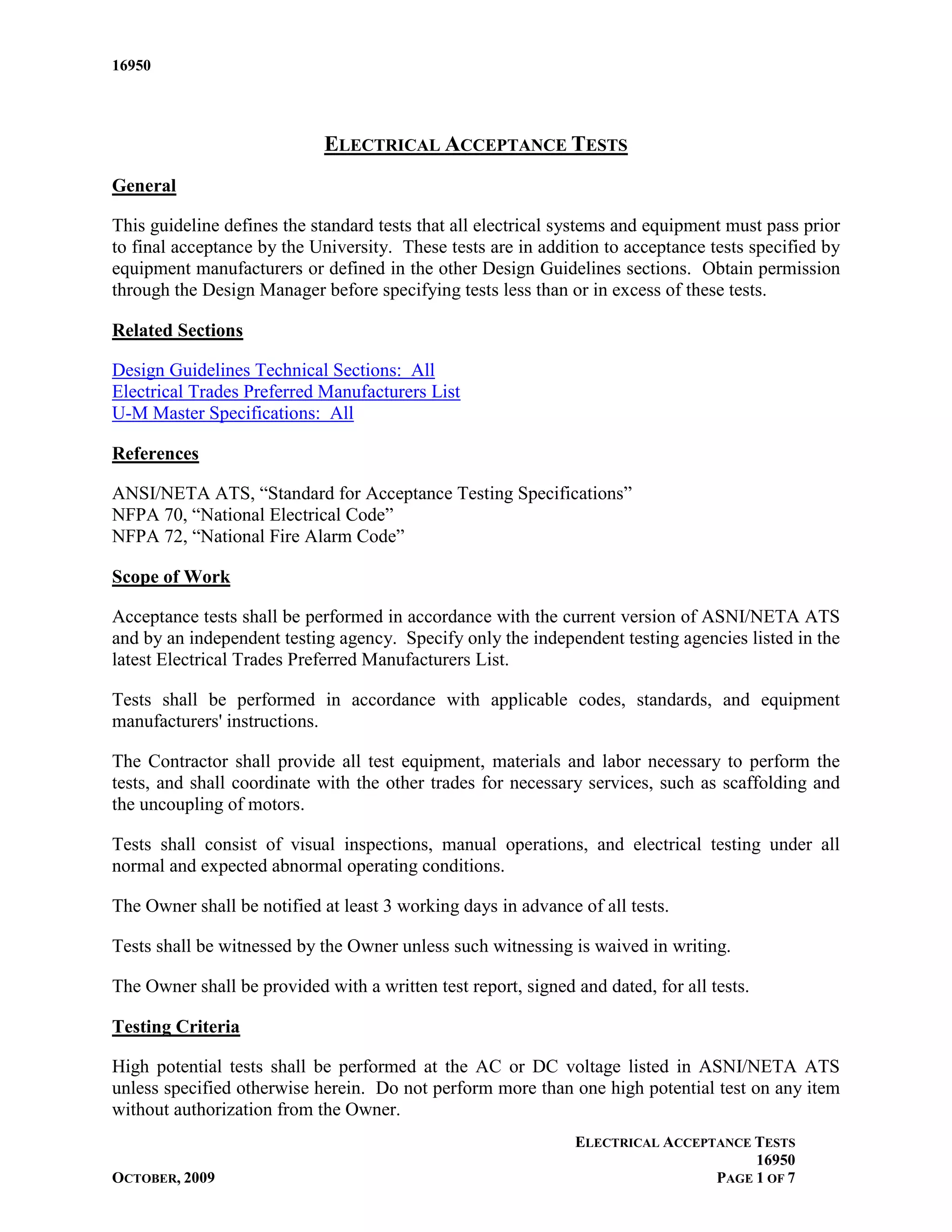
This guideline defines the standard tests that all electrical systems and equipment must pass prior
to final acceptance by the University. These tests are in addition to acceptance tests specified by
equipment manufacturers or defined in the other Design Guidelines sections. Obtain permission
through the Design Manager before specifying tests less than or in excess of these tests.

Related Sections

Design Guidelines Technical Sections: All
Electrical Trades Preferred Manufacturers List
U-M Master Specifications: All

References

ANSI/NETA ATS, “Standard for Acceptance Testing Specifications”
NFPA 70, “National Electrical Code”
NFPA 72, “National Fire Alarm Code”

Scope of Work

Acceptance tests shall be performed in accordance with the current version of ASNI/NETA ATS
and by an independent testing agency. Specify only the independent testing agencies listed in the
latest Electrical Trades Preferred Manufacturers List.

Tests shall be performed in accordance with applicable codes, standards, and equipment
manufacturers' instructions.

The Contractor shall provide all test equipment, materials and labor necessary to perform the
tests, and shall coordinate with the other trades for necessary services, such as scaffolding and
the uncoupling of motors.

Tests shall consist of visual inspections, manual operations, and electrical testing under all
normal and expected abnormal operating conditions.

The Owner shall be notified at least 3 working days in advance of all tests.

Tests shall be witnessed by the Owner unless such witnessing is waived in writing.

The Owner shall be provided with a written test report, signed and dated, for all tests.

Testing Criteria

High potential tests shall be performed at the AC or DC voltage listed in ASNI/NETA ATS
unless specified otherwise herein. Do not perform more than one high potential test on any item
without authorization from the Owner.
                                                               ELECTRICAL ACCEPTANCE TESTS
                                                                                     16950
OCTOBER, 2009                                                                   PAGE 1 OF 7
16950


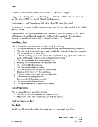
Dielectric absorption tests shall be performed with a 2,500 volt DC megger.

Megger tests shall be performed at a DC voltage of 1,000 volts for 600 volt rated equipment, and
at a DC voltage of 500 volts for 120-300 volt rated equipment.

Continuity checks shall be performed with a low voltage DC meter, light or bell.

The resistance to ground shall be measured using either the three point method or the fall-of-
potential method.

Test instruments shall be calibrated to national standards to insure the accuracy of tests. These
calibration reports shall be made available to the Owner when requested. Depending upon
frequency of use, the instruments shall be calibrated at least every 12 months.

Visual Inspections

Prior to manual operation and electrical testing, verify the following:
    • The equipment complies with the contract documents and the shop drawing submittals.
    • The equipment is completely and properly installed according to the contract documents
        and the manufacturer’s instructions.
    • Adequate working space exists around the equipment to fully open doors and access
        panels, and to access all components that require maintenance.
    • The equipment is free from damage and defects.
    • Shipping blocks and restraints have been removed.
    • The equipment has been aligned.
    • The equipment has been lubricated.
    • The ventilation louvers are open and unobstructed.
    • Electrical connections have been tightened.
    • Voltages, phases, and rotation have been identified.
    • Terminations have been identified.
    • Equipment labels have been installed.
    • The equipment has been calibrated.
    • The equipment is ready to be electrically tested.

Manual Operations

Prior to electrical testing, verify the following:
    • Mechanical components operate smoothly and freely.
    • Mechanical stops, limit switches, etc., are properly adjusted.

Electrical Acceptance Tests

Duct Banks

A stiff bristled brush shall be pulled through each duct to clean out dirt and debris.


                                                                ELECTRICAL ACCEPTANCE TESTS
                                                                                      16950
OCTOBER, 2009                                                                    PAGE 2 OF 7
16950


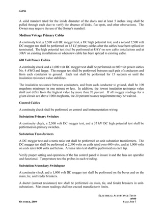
A solid mandrel rated for the inside diameter of the ducts and at least 5 inches long shall be
pulled through each duct to verify the absence of kinks, flat spots, and other obstructions. The
Owner may require the use of the Owner's mandrel.

Medium Voltage Primary Cables

A continuity test, a 2,500 volt DC megger test, a DC high potential test, and a second 2,500 volt
DC megger test shall be performed on 15 kV primary cables after the cables have been spliced or
terminated. The high potential test shall be performed at 45kV on new cable installations and at
30kV on existing installations or when new cable has been spliced to existing cable.

600 Volt Power Cables

A continuity check and a 1,000 volt DC megger test shall be performed on 600 volt power cables
No. 4 AWG and larger. The megger test shall be performed between each pair of conductors and
from each conductor to ground. Each test shall be performed for 15 seconds or until the
insulation resistance value stabilizes.

The insulation resistance between conductors, and from each conductor to ground, shall be 100
megohms minimum in one minute or less. In addition, the lowest insulation resistance value
shall not differ from the highest value by more than 20 percent. If all megger readings for a
given circuit are above 1000-meghoms, the 20 percent balance requirement may be waived.

Control Cables

A continuity check shall be performed on control and instrumentation wiring.

Substation Primary Switches

A continuity check, a 2,500 volt DC megger test, and a 37 kV DC high potential test shall be
performed on primary switches.

Substation Transformers

A DC megger test and a turns ratio test shall be performed on unit substation transformers. The
DC megger test shall be performed at 2,500 volts on coils rated over 600 volts, and at 1,000 volts
on coils rated 600 volts and below. A turns ratio test shall be performed on each tap.

Verify proper setting and operation of the fan control panel to insure it and the fans are operable
and functional. Temperature test the probes in each winding.

Substation Secondary Switchgear

A continuity check and a 1,000 volt DC megger test shall be performed on the buses and on the
main, tie, and feeder breakers.

A ducter (contact resistance) test shall be performed on main, tie, and feeder breakers in unit-
substations. Maximum readings shall not exceed manufacturer limits.

                                                              ELECTRICAL ACCEPTANCE TESTS
                                                                                    16950
OCTOBER, 2009                                                                  PAGE 3 OF 7
16950


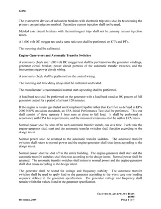
The overcurrent devices of substation breakers with electronic trip units shall be tested using the
primary current injection method. Secondary current injection shall not be used.

Molded case circuit breakers with thermal/magnet trips shall not be primary current injection
tested.

A 1,000 volt DC megger test and a turns ratio test shall be performed on CT's and PT's.

The metering shall be calibrated.

Engine-Generators and Automatic Transfer Switches

A continuity check and 1,000 volt DC megger test shall be performed on the generator windings,
generator circuit breaker, power circuit portions of the automatic transfer switches, and the
interconnecting power circuit wiring.

A continuity check shall be performed on the control wiring.

The metering and time delay relays shall be calibrated and tested.

The manufacturer’s recommended normal start-up testing shall be performed.

A load bank test shall be performed on the generator with a load bank rated at 100 percent of full
generator output for a period of at least 120 minutes.

If the engine is natural gas fueled and Compliant Capable rather than Certified as defined in EPA
2009 NSPS emissions standards, an EPA Initial Performance Test shall be performed. This test
shall consist of three separate 1 hour runs at close to full load. It shall be performed in
accordance with EPA test requirements, and the measured emissions shall be within EPA limits.

Normal power shall be shut off to each automatic transfer switch, one at a time. Each time the
engine-generator shall start and the automatic transfer switches shall function according to the
design intent.

Normal power shall be returned to the automatic transfer switches. The automatic transfer
switches shall return to normal power and the engine-generator shall shut down according to the
design intent.

Normal power shall be shut off to the entire building. The engine-generator shall start and the
automatic transfer switches shall function according to the design intent. Normal power shall be
returned. The automatic transfer switches shall return to normal power and the engine-generator
shall shut down according to the design intent.

The generator shall be tested for voltage and frequency stability. The automatic transfer
switches shall be used to apply load to the generator according to the worst case step loading
sequence defined in the generator specification. The generator voltage and frequency shall
remain within the values listed in the generator specification.


                                                               ELECTRICAL ACCEPTANCE TESTS
                                                                                     16950
OCTOBER, 2009                                                                   PAGE 4 OF 7
16950


The ATS maintenance bypass switches shall be inspected for proper labeling and tested for
proper operation in all modes.

The generator and automatic transfer switch controls, gauges, status indicators, and alarms,
including remote annunciators and devices in the Fire Command Center, shall be tested for
proper operation.

Alarm outputs to the fire alarm and BAS systems shall be verified.

Transformers, Reactors, Switchboards, Panelboards, and Motor Control Equipment

A continuity check and a 1,000 volt DC megger test shall be performed on distribution and
isolation transformers, and on line reactors.

A 1,000 volt DC megger test shall be performed on buses, motor starters, circuit breakers, and
disconnect switches. This test may be combined with the power cable megger test by testing the
devices and terminated cables together.

A continuity check shall be performed on motor control circuits and control panel internal
wiring.

An operational test shall be performed on the motor controls.

Motor heater sizes shall be checked for proper size.

Motors

A 1,000 volt megger test shall be performed on 460 volt motors. A 500 volt megger test shall be
performed on 200 volt and 120 volt motors.

Motors shall be “bumped” to verify proper direction of rotation.

Motors shall be run to verify proper ampere draw and to verify vibration and heating are within
required limits.

The Electrical Contractor shall assist the Temperature Control Contractor and the Mechanical
Contractor and insure proper operation of safeties, interlocks and motor controls.

Capacitors

Capacitors shall be inspected for proper fuses before testing. A 1,000 volt DC megger test shall
be performed on 460 volt capacitors, and a 500 volt megger test shall be performed on 200/240
volt capacitors. After each megger test, proper discharge shall be checked.


                                                                ELECTRICAL ACCEPTANCE TESTS
                                                                                      16950
OCTOBER, 2009                                                                    PAGE 5 OF 7
16950


Grounding

The resistance to ground of each ground rod in a ground mat shall be measured before
connection to the other ground rods. The resistance shall not exceed 10 ohms. If the reading
exceeds 10 ohms, add one extension and drive it another 10 feet. Further testing of that rod is
not needed.

The resistance to ground of the total ground system shall be measured with all connections
completed. The resistance shall not exceed 2 ohms for switching stations or utility (DTE) feed
point services; and shall not exceed 5 ohms for building service substations.

Ground rods for manholes and light poles need not be tested.

A continuity check shall be performed from equipment ground bus bars and ground lugs to the
ground system.

Lighting Fixtures

Lighting fixtures shall be checked for proper assembly, proper louvers or lenses, proper lamps,
proper ballasts, straight row alignment, proper aiming, and the absence of light leaks.

Battery-backed emergency lighting fixtures shall be checked for continuous operation for a
minimum of 90 minutes.

Lighting Circuits

Lighting circuits shall be checked for proper switching, for proper circuiting according to the
design documents, and for circuiting that matches the lighting panel schedules.

Lighting Controls and Dimming Systems

Lighting controls and dimming systems shall be tested to verify that they have the specified
features and programmability, and that all controls are properly labeled.

Lighting controls and dimming systems shall be tested to verify that the control sequences noted
in the contract documents and manufacturer’s instructions are present and operable, that control
and dimming are smooth and free of flicker, and that fading is properly timed.

Lighting controls and dimming systems shall be tested to verify that the emergency lights
function upon a loss of normal power.

Fire Alarm Systems

Fire alarm systems shall be tested in accordance with NFPA 72.

Controls that interface with the fire alarm system shall be tested in cooperation with the
Temperature Controls Contractor to insure proper operation of interfaced mechanical devices.


                                                               ELECTRICAL ACCEPTANCE TESTS
                                                                                     16950
OCTOBER, 2009                                                                   PAGE 6 OF 7
16950


Alarm, supervisory, and trouble outputs to the MOSCAD and BAS systems shall be tested to
insure that the signals are received by Public Safety or at Plant Operations.

Special Systems

Security systems, card access control systems, sound reinforcement systems, and other special
systems shall be tested in accordance with test plans submitted by their manufacturers and
approved by the Owner. These test plans shall verify compliance with specifications and proper
operation including all inputs, outputs, alarms, and accessories under all modes of operation.

Heat Tracing Cables and Mats

A continuity check, a 500 volt DC megger test, and an operational test shall be performed on
heat tracing circuits prior to insulation of the pipe or tank. Verify proper current draw and
heating of the heat tracing.

The 500 volt DC megger test shall be repeated after the insulation is completely installed.

An operational test shall be performed on the controls and alarms.


                                                              ELECTRICAL ACCEPTANCE TESTS
                                                                                    16950
OCTOBER, 2009                                                                  PAGE 7 OF 7

More Related Content

What's hot

Emc standards
Emc standardsEmc standards
Emc standardskandira
 
Selective Coordination
Selective CoordinationSelective Coordination
Selective Coordinationmichaeljmack
 
INSPECTION AND TEST PROCEDURES FOR SWITCHGEAR AND SWITCHBOARD
INSPECTION AND TEST PROCEDURES FOR SWITCHGEAR AND SWITCHBOARDINSPECTION AND TEST PROCEDURES FOR SWITCHGEAR AND SWITCHBOARD
INSPECTION AND TEST PROCEDURES FOR SWITCHGEAR AND SWITCHBOARDhussein ibrahim
 
A Comparison of Contemporary Electrical Distribution Equipment Standards
A Comparison of Contemporary Electrical Distribution Equipment StandardsA Comparison of Contemporary Electrical Distribution Equipment Standards
A Comparison of Contemporary Electrical Distribution Equipment Standardsmichaeljmack
 
Selective Coordination "The Rest of the Story"
Selective Coordination "The Rest of the Story"Selective Coordination "The Rest of the Story"
Selective Coordination "The Rest of the Story"michaeljmack
 
Siemens MV GIS Switchgear
Siemens MV GIS SwitchgearSiemens MV GIS Switchgear
Siemens MV GIS Switchgearmichaeljmack
 
Product catalogue KharkovEnergoPribor ltd.
Product catalogue KharkovEnergoPribor ltd.Product catalogue KharkovEnergoPribor ltd.
Product catalogue KharkovEnergoPribor ltd.KEP Power Testing Ltd.
 
Design and Development of 5MW Solar PV Grid Connected Power Plant using PVsyst
Design and Development of 5MW Solar PV Grid Connected Power Plant using PVsystDesign and Development of 5MW Solar PV Grid Connected Power Plant using PVsyst
Design and Development of 5MW Solar PV Grid Connected Power Plant using PVsystIRJET Journal
 
Power transformer testing and commissioning guidelines r
Power transformer testing and commissioning guidelines rPower transformer testing and commissioning guidelines r
Power transformer testing and commissioning guidelines rAshish Patel
 
Power transformer maintenance
Power transformer maintenancePower transformer maintenance
Power transformer maintenanceLucian Lazar
 
A2.34+transformer+maintenance+tutorial
A2.34+transformer+maintenance+tutorialA2.34+transformer+maintenance+tutorial
A2.34+transformer+maintenance+tutorialJack Duff
 

What's hot (20)

IEEE Blue Book
IEEE Blue BookIEEE Blue Book
IEEE Blue Book
 
Emc standards
Emc standardsEmc standards
Emc standards
 
Selective Coordination
Selective CoordinationSelective Coordination
Selective Coordination
 
EIT_Presentation
EIT_PresentationEIT_Presentation
EIT_Presentation
 
INSPECTION AND TEST PROCEDURES FOR SWITCHGEAR AND SWITCHBOARD
INSPECTION AND TEST PROCEDURES FOR SWITCHGEAR AND SWITCHBOARDINSPECTION AND TEST PROCEDURES FOR SWITCHGEAR AND SWITCHBOARD
INSPECTION AND TEST PROCEDURES FOR SWITCHGEAR AND SWITCHBOARD
 
Acs712
Acs712Acs712
Acs712
 
A Comparison of Contemporary Electrical Distribution Equipment Standards
A Comparison of Contemporary Electrical Distribution Equipment StandardsA Comparison of Contemporary Electrical Distribution Equipment Standards
A Comparison of Contemporary Electrical Distribution Equipment Standards
 
Selective Coordination "The Rest of the Story"
Selective Coordination "The Rest of the Story"Selective Coordination "The Rest of the Story"
Selective Coordination "The Rest of the Story"
 
Siemens MV GIS Switchgear
Siemens MV GIS SwitchgearSiemens MV GIS Switchgear
Siemens MV GIS Switchgear
 
Product catalogue KharkovEnergoPribor ltd.
Product catalogue KharkovEnergoPribor ltd.Product catalogue KharkovEnergoPribor ltd.
Product catalogue KharkovEnergoPribor ltd.
 
Design and Development of 5MW Solar PV Grid Connected Power Plant using PVsyst
Design and Development of 5MW Solar PV Grid Connected Power Plant using PVsystDesign and Development of 5MW Solar PV Grid Connected Power Plant using PVsyst
Design and Development of 5MW Solar PV Grid Connected Power Plant using PVsyst
 
Power transformer testing and commissioning guidelines r
Power transformer testing and commissioning guidelines rPower transformer testing and commissioning guidelines r
Power transformer testing and commissioning guidelines r
 
Thông số bộ đổi nguồn Mean Well, Catalogue Bộ đổi nguồn Mean Well, Meanwell
Thông số bộ đổi nguồn Mean Well, Catalogue Bộ đổi nguồn Mean Well, MeanwellThông số bộ đổi nguồn Mean Well, Catalogue Bộ đổi nguồn Mean Well, Meanwell
Thông số bộ đổi nguồn Mean Well, Catalogue Bộ đổi nguồn Mean Well, Meanwell
 
Transformers
TransformersTransformers
Transformers
 
Power transformer maintenance
Power transformer maintenancePower transformer maintenance
Power transformer maintenance
 
A2.34+transformer+maintenance+tutorial
A2.34+transformer+maintenance+tutorialA2.34+transformer+maintenance+tutorial
A2.34+transformer+maintenance+tutorial
 
Pragati pt cataloge
Pragati pt catalogePragati pt cataloge
Pragati pt cataloge
 
EV Charging Stations
EV Charging StationsEV Charging Stations
EV Charging Stations
 
EIT_Presentation
EIT_PresentationEIT_Presentation
EIT_Presentation
 
EIT_Presentation
EIT_PresentationEIT_Presentation
EIT_Presentation
 

Similar to 16950

Isolator and bushing
Isolator and bushingIsolator and bushing
Isolator and bushingNovia Putri
 
AC Circuit Breakers Routine Tests according to IEC 62271-100
AC Circuit Breakers Routine Tests according to IEC 62271-100AC Circuit Breakers Routine Tests according to IEC 62271-100
AC Circuit Breakers Routine Tests according to IEC 62271-100Ali Sepehri
 
AC High voltage Air Break Disconnector Switch Routine Test According to IEC 6...
AC High voltage Air Break Disconnector Switch Routine Test According to IEC 6...AC High voltage Air Break Disconnector Switch Routine Test According to IEC 6...
AC High voltage Air Break Disconnector Switch Routine Test According to IEC 6...Ali Sepehri
 
INSTALLATION OF 500MVA TRANSFORMER AT PGCIL
INSTALLATION OF 500MVA TRANSFORMER AT PGCIL INSTALLATION OF 500MVA TRANSFORMER AT PGCIL
INSTALLATION OF 500MVA TRANSFORMER AT PGCIL Rahul Akinapelli
 
13-Webinar-Transformer-Maintenance-Testing-Fundamentals-06-26-18.pdf
13-Webinar-Transformer-Maintenance-Testing-Fundamentals-06-26-18.pdf13-Webinar-Transformer-Maintenance-Testing-Fundamentals-06-26-18.pdf
13-Webinar-Transformer-Maintenance-Testing-Fundamentals-06-26-18.pdfvikram desai
 
Testing of circuit breakers
Testing of circuit breakersTesting of circuit breakers
Testing of circuit breakersKabilesh K
 
Testing of c.b.(hk & hr) nihal
Testing of c.b.(hk & hr) nihalTesting of c.b.(hk & hr) nihal
Testing of c.b.(hk & hr) nihalNihal Shiroya
 
'docslide.us_hv-testing.ppt
'docslide.us_hv-testing.ppt'docslide.us_hv-testing.ppt
'docslide.us_hv-testing.pptThien Phan Bản
 
Sona Electric Power Engineering and Testing Centre
Sona Electric Power Engineering and Testing CentreSona Electric Power Engineering and Testing Centre
Sona Electric Power Engineering and Testing CentreSona College of Technology
 
Relay testing.............................
Relay testing.............................Relay testing.............................
Relay testing.............................hiiarindam
 
Presentation OutDoorSwithGear(AIS) .pptx
Presentation OutDoorSwithGear(AIS) .pptxPresentation OutDoorSwithGear(AIS) .pptx
Presentation OutDoorSwithGear(AIS) .pptxRAJKIRANR3
 
REPORT -VALLUR THERMAL POWER PLANT
REPORT -VALLUR THERMAL POWER PLANTREPORT -VALLUR THERMAL POWER PLANT
REPORT -VALLUR THERMAL POWER PLANTRAJPRASAD RS
 
switchgearpresentation-151030171028-lva1-app6892.pptx
switchgearpresentation-151030171028-lva1-app6892.pptxswitchgearpresentation-151030171028-lva1-app6892.pptx
switchgearpresentation-151030171028-lva1-app6892.pptxDrNiveditaSingh3
 
Surge diverter
Surge diverterSurge diverter
Surge divertersarunkutti
 
Switchgear presentation
Switchgear presentationSwitchgear presentation
Switchgear presentationNadir Baloch
 
High Voltage Gas Insulated Substation (GIS) Routine Tests According to IEEE C...
High Voltage Gas Insulated Substation (GIS) Routine Tests According to IEEE C...High Voltage Gas Insulated Substation (GIS) Routine Tests According to IEEE C...
High Voltage Gas Insulated Substation (GIS) Routine Tests According to IEEE C...Ali Sepehri
 

Similar to 16950 (20)

Isolator and bushing
Isolator and bushingIsolator and bushing
Isolator and bushing
 
AC Circuit Breakers Routine Tests according to IEC 62271-100
AC Circuit Breakers Routine Tests according to IEC 62271-100AC Circuit Breakers Routine Tests according to IEC 62271-100
AC Circuit Breakers Routine Tests according to IEC 62271-100
 
AC High voltage Air Break Disconnector Switch Routine Test According to IEC 6...
AC High voltage Air Break Disconnector Switch Routine Test According to IEC 6...AC High voltage Air Break Disconnector Switch Routine Test According to IEC 6...
AC High voltage Air Break Disconnector Switch Routine Test According to IEC 6...
 
INSTALLATION OF 500MVA TRANSFORMER AT PGCIL
INSTALLATION OF 500MVA TRANSFORMER AT PGCIL INSTALLATION OF 500MVA TRANSFORMER AT PGCIL
INSTALLATION OF 500MVA TRANSFORMER AT PGCIL
 
13-Webinar-Transformer-Maintenance-Testing-Fundamentals-06-26-18.pdf
13-Webinar-Transformer-Maintenance-Testing-Fundamentals-06-26-18.pdf13-Webinar-Transformer-Maintenance-Testing-Fundamentals-06-26-18.pdf
13-Webinar-Transformer-Maintenance-Testing-Fundamentals-06-26-18.pdf
 
Testing of circuit breakers
Testing of circuit breakersTesting of circuit breakers
Testing of circuit breakers
 
Testing of c.b.(hk & hr) nihal
Testing of c.b.(hk & hr) nihalTesting of c.b.(hk & hr) nihal
Testing of c.b.(hk & hr) nihal
 
'docslide.us_hv-testing.ppt
'docslide.us_hv-testing.ppt'docslide.us_hv-testing.ppt
'docslide.us_hv-testing.ppt
 
Sona Electric Power Engineering and Testing Centre
Sona Electric Power Engineering and Testing CentreSona Electric Power Engineering and Testing Centre
Sona Electric Power Engineering and Testing Centre
 
ET 5 LESSON 2 TEST EQUIPMENT.pptx
ET 5 LESSON 2 TEST EQUIPMENT.pptxET 5 LESSON 2 TEST EQUIPMENT.pptx
ET 5 LESSON 2 TEST EQUIPMENT.pptx
 
Relay testing.............................
Relay testing.............................Relay testing.............................
Relay testing.............................
 
Fundamentals of Field Testing Meters
Fundamentals of Field Testing MetersFundamentals of Field Testing Meters
Fundamentals of Field Testing Meters
 
Module 6part1
Module 6part1Module 6part1
Module 6part1
 
Testing of cb
Testing of cbTesting of cb
Testing of cb
 
Presentation OutDoorSwithGear(AIS) .pptx
Presentation OutDoorSwithGear(AIS) .pptxPresentation OutDoorSwithGear(AIS) .pptx
Presentation OutDoorSwithGear(AIS) .pptx
 
REPORT -VALLUR THERMAL POWER PLANT
REPORT -VALLUR THERMAL POWER PLANTREPORT -VALLUR THERMAL POWER PLANT
REPORT -VALLUR THERMAL POWER PLANT
 
switchgearpresentation-151030171028-lva1-app6892.pptx
switchgearpresentation-151030171028-lva1-app6892.pptxswitchgearpresentation-151030171028-lva1-app6892.pptx
switchgearpresentation-151030171028-lva1-app6892.pptx
 
Surge diverter
Surge diverterSurge diverter
Surge diverter
 
Switchgear presentation
Switchgear presentationSwitchgear presentation
Switchgear presentation
 
High Voltage Gas Insulated Substation (GIS) Routine Tests According to IEEE C...
High Voltage Gas Insulated Substation (GIS) Routine Tests According to IEEE C...High Voltage Gas Insulated Substation (GIS) Routine Tests According to IEEE C...
High Voltage Gas Insulated Substation (GIS) Routine Tests According to IEEE C...
 

16950

  • 1. 16950 ELECTRICAL ACCEPTANCE TESTS General This guideline defines the standard tests that all electrical systems and equipment must pass prior to final acceptance by the University. These tests are in addition to acceptance tests specified by equipment manufacturers or defined in the other Design Guidelines sections. Obtain permission through the Design Manager before specifying tests less than or in excess of these tests. Related Sections Design Guidelines Technical Sections: All Electrical Trades Preferred Manufacturers List U-M Master Specifications: All References ANSI/NETA ATS, “Standard for Acceptance Testing Specifications” NFPA 70, “National Electrical Code” NFPA 72, “National Fire Alarm Code” Scope of Work Acceptance tests shall be performed in accordance with the current version of ASNI/NETA ATS and by an independent testing agency. Specify only the independent testing agencies listed in the latest Electrical Trades Preferred Manufacturers List. Tests shall be performed in accordance with applicable codes, standards, and equipment manufacturers' instructions. The Contractor shall provide all test equipment, materials and labor necessary to perform the tests, and shall coordinate with the other trades for necessary services, such as scaffolding and the uncoupling of motors. Tests shall consist of visual inspections, manual operations, and electrical testing under all normal and expected abnormal operating conditions. The Owner shall be notified at least 3 working days in advance of all tests. Tests shall be witnessed by the Owner unless such witnessing is waived in writing. The Owner shall be provided with a written test report, signed and dated, for all tests. Testing Criteria High potential tests shall be performed at the AC or DC voltage listed in ASNI/NETA ATS unless specified otherwise herein. Do not perform more than one high potential test on any item without authorization from the Owner. ELECTRICAL ACCEPTANCE TESTS 16950 OCTOBER, 2009 PAGE 1 OF 7
  • 2. 16950 Dielectric absorption tests shall be performed with a 2,500 volt DC megger. Megger tests shall be performed at a DC voltage of 1,000 volts for 600 volt rated equipment, and at a DC voltage of 500 volts for 120-300 volt rated equipment. Continuity checks shall be performed with a low voltage DC meter, light or bell. The resistance to ground shall be measured using either the three point method or the fall-of- potential method. Test instruments shall be calibrated to national standards to insure the accuracy of tests. These calibration reports shall be made available to the Owner when requested. Depending upon frequency of use, the instruments shall be calibrated at least every 12 months. Visual Inspections Prior to manual operation and electrical testing, verify the following: • The equipment complies with the contract documents and the shop drawing submittals. • The equipment is completely and properly installed according to the contract documents and the manufacturer’s instructions. • Adequate working space exists around the equipment to fully open doors and access panels, and to access all components that require maintenance. • The equipment is free from damage and defects. • Shipping blocks and restraints have been removed. • The equipment has been aligned. • The equipment has been lubricated. • The ventilation louvers are open and unobstructed. • Electrical connections have been tightened. • Voltages, phases, and rotation have been identified. • Terminations have been identified. • Equipment labels have been installed. • The equipment has been calibrated. • The equipment is ready to be electrically tested. Manual Operations Prior to electrical testing, verify the following: • Mechanical components operate smoothly and freely. • Mechanical stops, limit switches, etc., are properly adjusted. Electrical Acceptance Tests Duct Banks A stiff bristled brush shall be pulled through each duct to clean out dirt and debris. ELECTRICAL ACCEPTANCE TESTS 16950 OCTOBER, 2009 PAGE 2 OF 7
  • 3. 16950 A solid mandrel rated for the inside diameter of the ducts and at least 5 inches long shall be pulled through each duct to verify the absence of kinks, flat spots, and other obstructions. The Owner may require the use of the Owner's mandrel. Medium Voltage Primary Cables A continuity test, a 2,500 volt DC megger test, a DC high potential test, and a second 2,500 volt DC megger test shall be performed on 15 kV primary cables after the cables have been spliced or terminated. The high potential test shall be performed at 45kV on new cable installations and at 30kV on existing installations or when new cable has been spliced to existing cable. 600 Volt Power Cables A continuity check and a 1,000 volt DC megger test shall be performed on 600 volt power cables No. 4 AWG and larger. The megger test shall be performed between each pair of conductors and from each conductor to ground. Each test shall be performed for 15 seconds or until the insulation resistance value stabilizes. The insulation resistance between conductors, and from each conductor to ground, shall be 100 megohms minimum in one minute or less. In addition, the lowest insulation resistance value shall not differ from the highest value by more than 20 percent. If all megger readings for a given circuit are above 1000-meghoms, the 20 percent balance requirement may be waived. Control Cables A continuity check shall be performed on control and instrumentation wiring. Substation Primary Switches A continuity check, a 2,500 volt DC megger test, and a 37 kV DC high potential test shall be performed on primary switches. Substation Transformers A DC megger test and a turns ratio test shall be performed on unit substation transformers. The DC megger test shall be performed at 2,500 volts on coils rated over 600 volts, and at 1,000 volts on coils rated 600 volts and below. A turns ratio test shall be performed on each tap. Verify proper setting and operation of the fan control panel to insure it and the fans are operable and functional. Temperature test the probes in each winding. Substation Secondary Switchgear A continuity check and a 1,000 volt DC megger test shall be performed on the buses and on the main, tie, and feeder breakers. A ducter (contact resistance) test shall be performed on main, tie, and feeder breakers in unit- substations. Maximum readings shall not exceed manufacturer limits. ELECTRICAL ACCEPTANCE TESTS 16950 OCTOBER, 2009 PAGE 3 OF 7
  • 4. 16950 The overcurrent devices of substation breakers with electronic trip units shall be tested using the primary current injection method. Secondary current injection shall not be used. Molded case circuit breakers with thermal/magnet trips shall not be primary current injection tested. A 1,000 volt DC megger test and a turns ratio test shall be performed on CT's and PT's. The metering shall be calibrated. Engine-Generators and Automatic Transfer Switches A continuity check and 1,000 volt DC megger test shall be performed on the generator windings, generator circuit breaker, power circuit portions of the automatic transfer switches, and the interconnecting power circuit wiring. A continuity check shall be performed on the control wiring. The metering and time delay relays shall be calibrated and tested. The manufacturer’s recommended normal start-up testing shall be performed. A load bank test shall be performed on the generator with a load bank rated at 100 percent of full generator output for a period of at least 120 minutes. If the engine is natural gas fueled and Compliant Capable rather than Certified as defined in EPA 2009 NSPS emissions standards, an EPA Initial Performance Test shall be performed. This test shall consist of three separate 1 hour runs at close to full load. It shall be performed in accordance with EPA test requirements, and the measured emissions shall be within EPA limits. Normal power shall be shut off to each automatic transfer switch, one at a time. Each time the engine-generator shall start and the automatic transfer switches shall function according to the design intent. Normal power shall be returned to the automatic transfer switches. The automatic transfer switches shall return to normal power and the engine-generator shall shut down according to the design intent. Normal power shall be shut off to the entire building. The engine-generator shall start and the automatic transfer switches shall function according to the design intent. Normal power shall be returned. The automatic transfer switches shall return to normal power and the engine-generator shall shut down according to the design intent. The generator shall be tested for voltage and frequency stability. The automatic transfer switches shall be used to apply load to the generator according to the worst case step loading sequence defined in the generator specification. The generator voltage and frequency shall remain within the values listed in the generator specification. ELECTRICAL ACCEPTANCE TESTS 16950 OCTOBER, 2009 PAGE 4 OF 7
  • 5. 16950 The ATS maintenance bypass switches shall be inspected for proper labeling and tested for proper operation in all modes. The generator and automatic transfer switch controls, gauges, status indicators, and alarms, including remote annunciators and devices in the Fire Command Center, shall be tested for proper operation. Alarm outputs to the fire alarm and BAS systems shall be verified. Transformers, Reactors, Switchboards, Panelboards, and Motor Control Equipment A continuity check and a 1,000 volt DC megger test shall be performed on distribution and isolation transformers, and on line reactors. A 1,000 volt DC megger test shall be performed on buses, motor starters, circuit breakers, and disconnect switches. This test may be combined with the power cable megger test by testing the devices and terminated cables together. A continuity check shall be performed on motor control circuits and control panel internal wiring. An operational test shall be performed on the motor controls. Motor heater sizes shall be checked for proper size. Motors A 1,000 volt megger test shall be performed on 460 volt motors. A 500 volt megger test shall be performed on 200 volt and 120 volt motors. Motors shall be “bumped” to verify proper direction of rotation. Motors shall be run to verify proper ampere draw and to verify vibration and heating are within required limits. The Electrical Contractor shall assist the Temperature Control Contractor and the Mechanical Contractor and insure proper operation of safeties, interlocks and motor controls. Capacitors Capacitors shall be inspected for proper fuses before testing. A 1,000 volt DC megger test shall be performed on 460 volt capacitors, and a 500 volt megger test shall be performed on 200/240 volt capacitors. After each megger test, proper discharge shall be checked. ELECTRICAL ACCEPTANCE TESTS 16950 OCTOBER, 2009 PAGE 5 OF 7
  • 6. 16950 Grounding The resistance to ground of each ground rod in a ground mat shall be measured before connection to the other ground rods. The resistance shall not exceed 10 ohms. If the reading exceeds 10 ohms, add one extension and drive it another 10 feet. Further testing of that rod is not needed. The resistance to ground of the total ground system shall be measured with all connections completed. The resistance shall not exceed 2 ohms for switching stations or utility (DTE) feed point services; and shall not exceed 5 ohms for building service substations. Ground rods for manholes and light poles need not be tested. A continuity check shall be performed from equipment ground bus bars and ground lugs to the ground system. Lighting Fixtures Lighting fixtures shall be checked for proper assembly, proper louvers or lenses, proper lamps, proper ballasts, straight row alignment, proper aiming, and the absence of light leaks. Battery-backed emergency lighting fixtures shall be checked for continuous operation for a minimum of 90 minutes. Lighting Circuits Lighting circuits shall be checked for proper switching, for proper circuiting according to the design documents, and for circuiting that matches the lighting panel schedules. Lighting Controls and Dimming Systems Lighting controls and dimming systems shall be tested to verify that they have the specified features and programmability, and that all controls are properly labeled. Lighting controls and dimming systems shall be tested to verify that the control sequences noted in the contract documents and manufacturer’s instructions are present and operable, that control and dimming are smooth and free of flicker, and that fading is properly timed. Lighting controls and dimming systems shall be tested to verify that the emergency lights function upon a loss of normal power. Fire Alarm Systems Fire alarm systems shall be tested in accordance with NFPA 72. Controls that interface with the fire alarm system shall be tested in cooperation with the Temperature Controls Contractor to insure proper operation of interfaced mechanical devices. ELECTRICAL ACCEPTANCE TESTS 16950 OCTOBER, 2009 PAGE 6 OF 7
  • 7. 16950 Alarm, supervisory, and trouble outputs to the MOSCAD and BAS systems shall be tested to insure that the signals are received by Public Safety or at Plant Operations. Special Systems Security systems, card access control systems, sound reinforcement systems, and other special systems shall be tested in accordance with test plans submitted by their manufacturers and approved by the Owner. These test plans shall verify compliance with specifications and proper operation including all inputs, outputs, alarms, and accessories under all modes of operation. Heat Tracing Cables and Mats A continuity check, a 500 volt DC megger test, and an operational test shall be performed on heat tracing circuits prior to insulation of the pipe or tank. Verify proper current draw and heating of the heat tracing. The 500 volt DC megger test shall be repeated after the insulation is completely installed. An operational test shall be performed on the controls and alarms. ELECTRICAL ACCEPTANCE TESTS 16950 OCTOBER, 2009 PAGE 7 OF 7