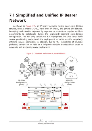
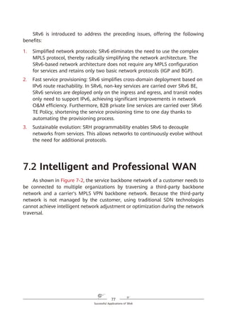
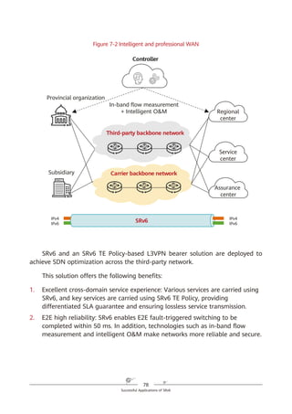
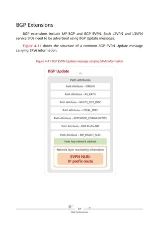
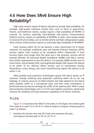
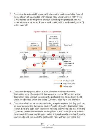
This document provides a comprehensive overview of Segment Routing over IPv6 (SRv6), detailing its technical advantages, implementation, and relevance in modern networking. It outlines the challenges faced by traditional IP/MPLS networks and explains how SRv6 offers simplified network protocols and enhanced flexibility, making it suitable for 5G and cloud services. The book aims to educate network professionals and managers on the implications and applications of SRv6 in the evolving landscape of IP networking.


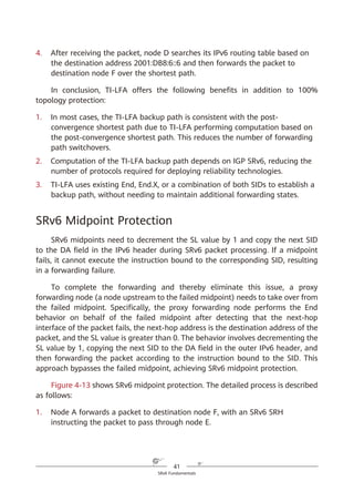
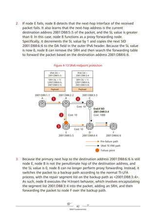
![23
SRv6 Fundamentals
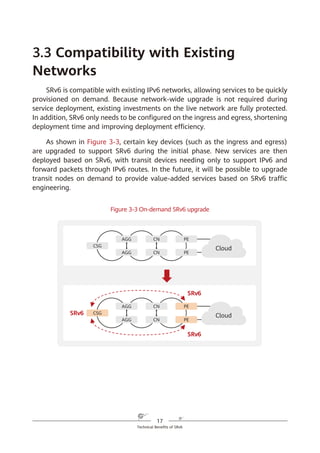
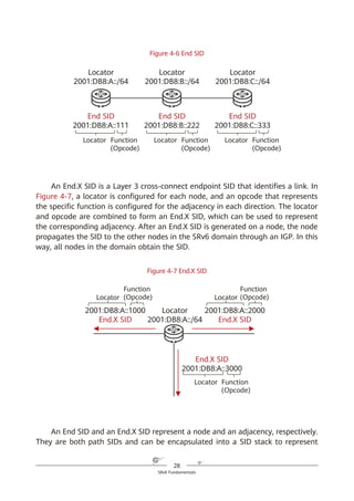
of IPv6. With SRv6, services can reach the destination as long as the corresponding
routes are reachable, and they can easily span ASs thanks to the AS spanning
capability of routes. This simplifies network deployment and facilitates network
expansion.
4.2 How Is IPv6 Extended to Support
SRv6?
IPv6 SRH
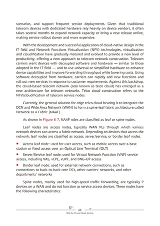
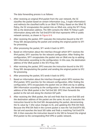
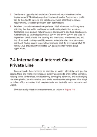
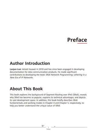
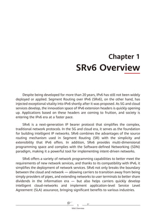
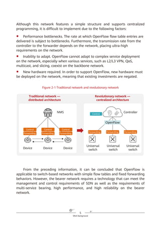
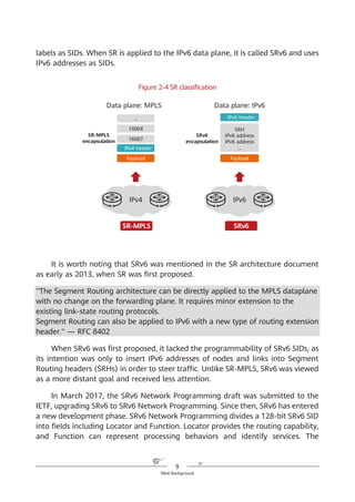
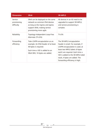
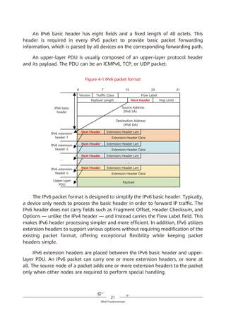
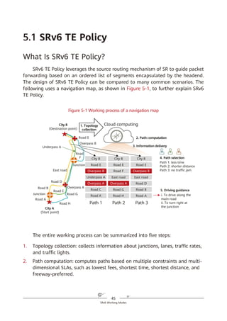
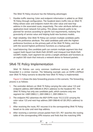
To implement SR based on the IPv6 forwarding plane, a new type of IPv6 RH
called Segment Routing Header (SRH) is defined. The SRH, which the ingress adds
to each IPv6 packet, stores IPv6 path constraint information (segment lists) to
specify an IPv6 explicit path. Transit nodes forward the packets according to the
path information contained in the SRH. Figure 4-2 shows the SRH format.
Figure 4-2 SRH format
Segment list
Next Header Hdr Ext Len Routing Type
Segment List [0] (128-bit IPv6 address)
Segments Left
Last Entry Flags Tag
…
Segment List [n] (128-bit IPv6 address)
Optional TLV objects (variable)
IPv6 Basic Header Segment Routing Header Payload
0 7 15 23 31
IPv6 SRH](https://image.slidesharecdn.com/ipv6srv6-240704021558-4ea0e87c/85/Technology-Tutorial-The-Basics-Of-IPv6-SRv6-29-320.jpg)
![24
SRv6 Fundamentals
The key information in the IPv6 SRH is as follows:
1. Routing Type: If the value of this field is 4, the packet header is an SRH.
2. Segment List (Segment List [0], Segment List [1], Segment List [2], ...,
Segment List [n]): This field indicates network path information.
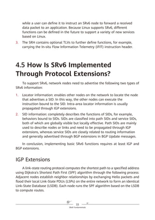
3. Segments Left (SL): This field is a pointer that indicates the currently active
segment.
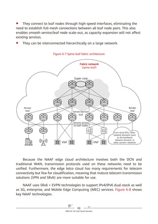
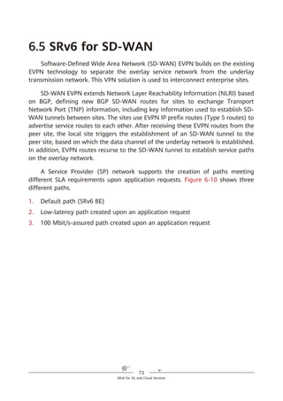
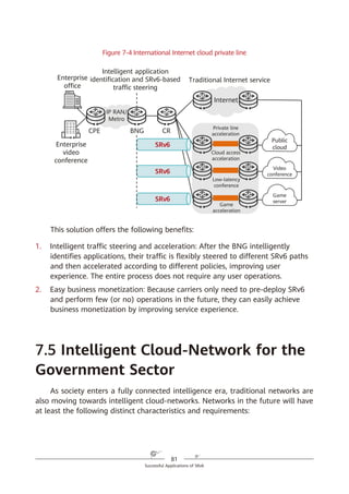
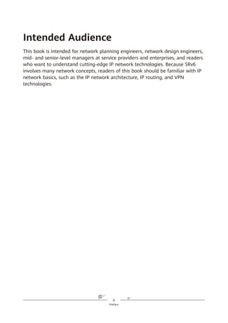
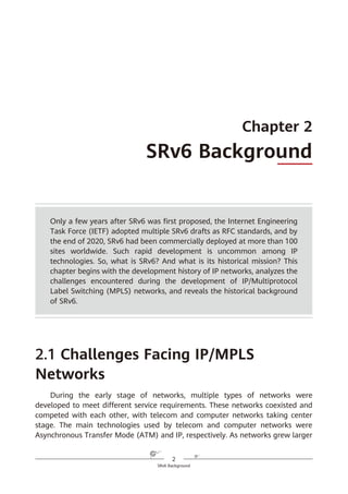
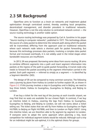
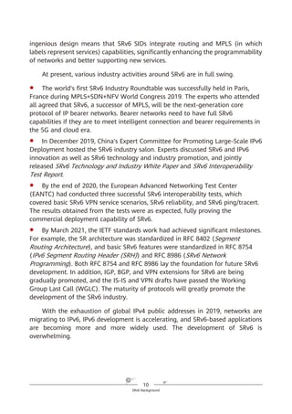
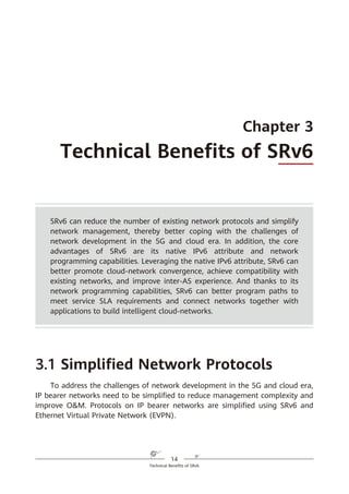
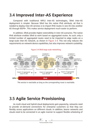
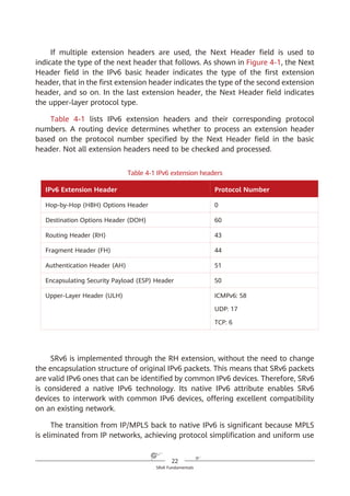
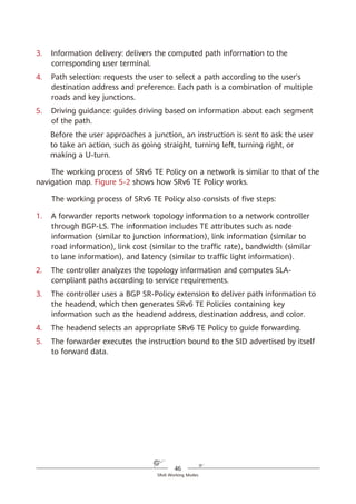
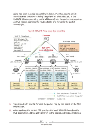
To make it easier to explain data forwarding, the SRH can be expressed using
an abstract format shown in Figure 4-3. The SIDs in (a) are listed in forward
order and identified using < >, whereas those in (b) are listed in reverse order
and identified using ( ). The reverse order more closely represents actual SRv6
packet encapsulation.
Figure 4-3 Abstract SRH
SRv6 SRH Processing
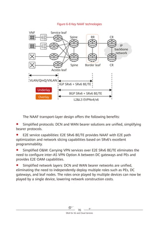
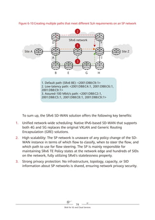
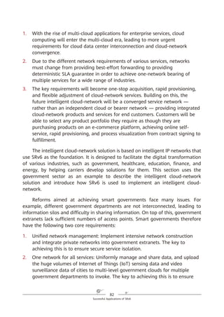
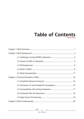
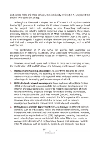
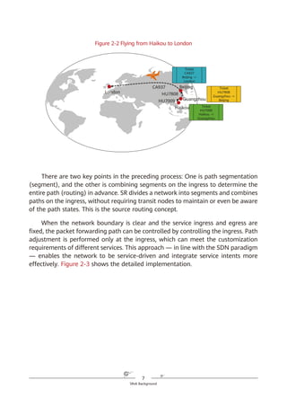
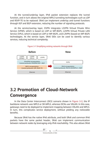
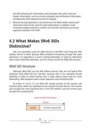
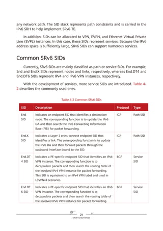
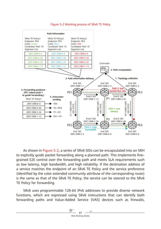
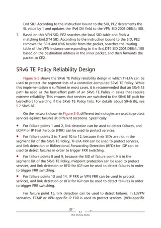
In an SRv6 SRH, the SL pointer and segment list information are used together
to determine the IPv6 Destination Address (DA) in the packet header. The value
of the SL pointer ranges from 0 (minimum) to the number of SIDs in the SRH
minus 1 (maximum). As shown in Figure 4-4, each time a packet passes through
an SRv6 node, the value of the SL field is decremented by 1 and the IPv6 DA is
updated to the SID that the pointer currently points to.
IPv6 SA = Local IPv6 address
IPv6 DA = Segment List [0]
(a)
SRH (SL = n)
<Segment List [0] = SID [0],
Segment List [1] = SID [1],
…,
Segment List [n – 1] = SID [n – 1],
Segment List [n] = SID [n]>
Payload
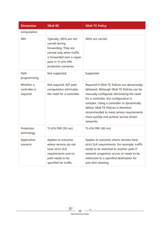
IPv6 SA = Local IPv6 address
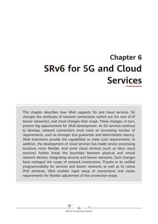
IPv6 DA = SID [0]
SRH (SL = n)
(SID [n],
SID [n – 1],
…,
SID [1],
SID [0])
Payload
(b)](https://image.slidesharecdn.com/ipv6srv6-240704021558-4ea0e87c/85/Technology-Tutorial-The-Basics-Of-IPv6-SRv6-30-320.jpg)
![25
SRv6 Fundamentals
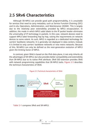
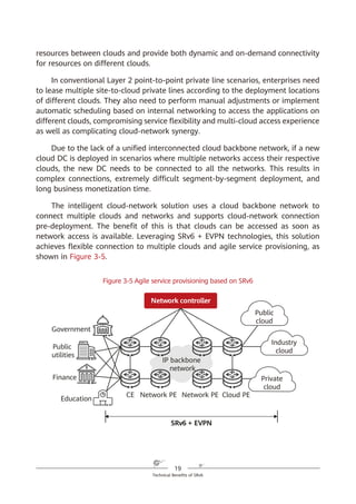
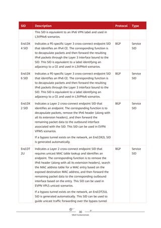
If the SL value is n, the IPv6 DA value is equal to the Segment List [n] value.
If the SL value is n – 1, the IPv6 DA value is equal to the Segment List [n –
1] value.
...
If the SL value is 1, the IPv6 DA value is equal to the Segment List [1] value.
If the SL value is 0, the IPv6 DA value is equal to the Segment List [0] value.
If a node does not support SRv6, it searches the IPv6 routing table based on
the longest match rule for packet forwarding instead of performing the preceding
actions.
Figure 4-4 SRH processing
According to the above description, a node operates the SRv6 SRH from the
bottom up, which is different from what the node does in SR-MPLS scenarios.
Another difference between SRv6 and SR-MPLS is that a node does not pop
segments in the SRv6 SRH after processing them. This is mainly due to the
following three reasons:
1. The initial design of the IPv6 RH was not closely related to MPLS, causing
the unavailability of the pop option at the time.
2. In contrast to MPLS labels that are independently placed on the top of
packets and can therefore be directly removed, SRv6 segments are placed in
Network
SRv6 source node SID [0] SID [1] SID [n – 1] SID [n]
…
IPv6 DA =
SID [0]
SRH (SL = n)
(SID [n]
SID [n – 1],
...,
SID [1],
SID [0])
IPv6 DA =
SID [1]
SRH (SL = n – 1)
(SID [n]
SID [n – 1],
...,
SID [1],
SID [0])
IPv6 DA =
SID [n – 1]
SRH (SL = 1)
(SID [n]
SID [n – 1],
...,
SID [1],
SID [0])
IPv6 DA =
SID [n]
SRH (SL = 0)
(SID [n]
SID [n – 1],
...,
SID [1],
SID [0])](https://image.slidesharecdn.com/ipv6srv6-240704021558-4ea0e87c/85/Technology-Tutorial-The-Basics-Of-IPv6-SRv6-31-320.jpg)
![32
SRv6 Fundamentals
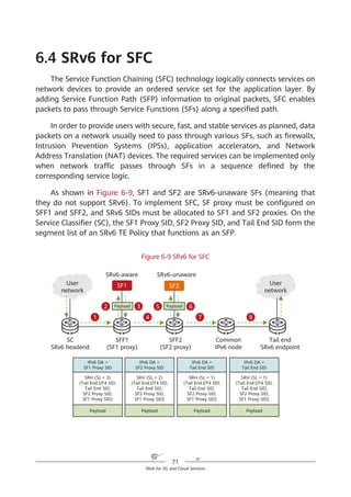
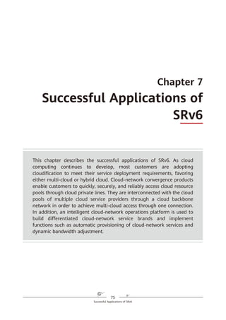
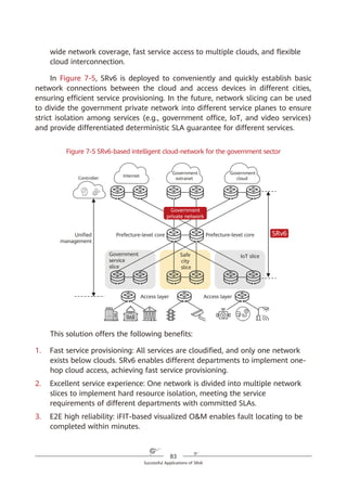
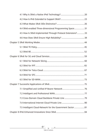
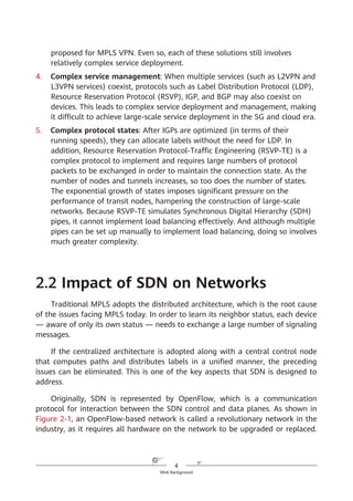
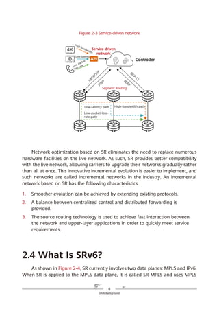
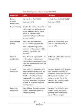
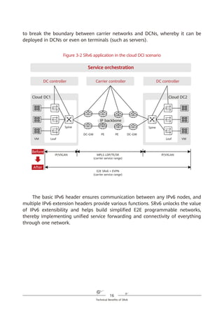
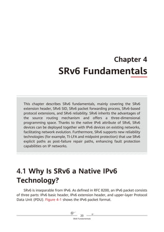
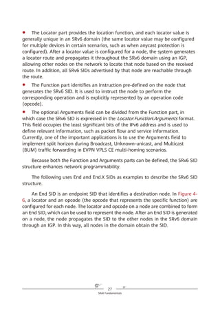
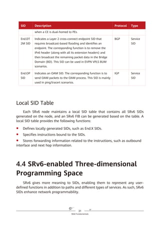
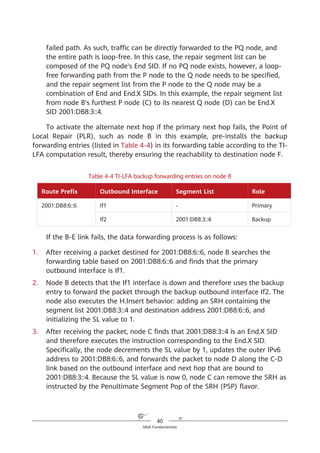
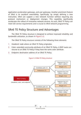
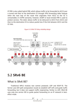
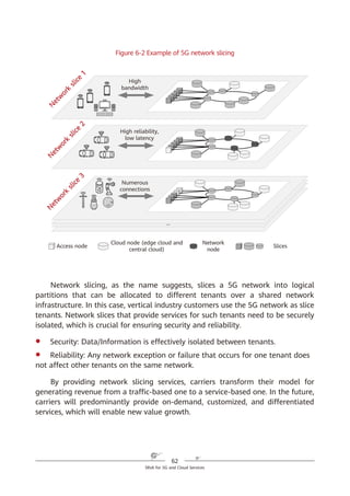
SRv6 supports a three-dimensional programming space, as shown in Figure
4-8.
1. SRv6 SIDs can be flexibly combined for path programming. After a service
requirement is raised, the controller responds to the requirement and
defines a forwarding path accordingly. This approach complies with the SDN
paradigm. For example, company A needs to provision services for company
B within a month, requiring a large amount of data to be exchanged.
Bandwidth must therefore be guaranteed immediately. To achieve this,
company A needs to purchase corresponding services from a carrier for one
month. Traditionally, service provisioning usually takes months to complete
because multiple departments need to work together, meaning that
company A will fail to meet the deadline. In contrast, SRv6 path
programming enables the carrier's controller to quickly respond to the
company's requirement, compute SLA-compliant service paths, and quickly
complete service provisioning. Furthermore, the carrier can quickly tear
down relevant connections to release network resources after the one-
month period expires.
Figure 4-8 SRv6-enabled three-dimensional programming space
2. The Function and Arguments fields can be defined. Device vendors can
define the Function field at present, although users will also be able to
define it in the future. For example, a device vendor can define this field to
instruct an SRv6 egress to forward a received data packet to a VPN instance,
2. The SID structure and function can be defined.
Locator Function Arguments
Length X Length Y Length Z
Used for routing to the
node that needs to
implement the function
Represents any
instruction bound
to the local node
Optional and used
to further define
the function
Flexible length allocation: X + Y + Z = 128
Destination SRH L2/L3 Payload
Source
Segment List [0]
Segment List [1]
…
Segment List [n]
Optional TLV
1. SIDs can be
flexibly combined.
3. The function can
be further defined.
SRv6 packet](https://image.slidesharecdn.com/ipv6srv6-240704021558-4ea0e87c/85/Technology-Tutorial-The-Basics-Of-IPv6-SRv6-38-320.jpg)
![53
SRv6 Working Modes
As shown in Figure 5-6, SRv6 BE packets are not encapsulated with SRHs,
which are used to represent path constraints. Because the format and forwarding
behavior of SRv6 BE packets are the same as those of common IPv6 packets —
meaning that common IPv6 devices can also process SRv6 BE packets — SRv6 is
compatible with such devices.
Figure 5-6 SRv6 BE packet encapsulation format
SRv6 BE packet encapsulation differs from common IPv6 packet encapsulation
in that the destination address of a common IPv6 packet is a host or subnet,
whereas that of an SRv6 BE packet is a service SID. The service SID can direct
packet forwarding along the shortest path to the parent node where the SID is
generated. After receiving a packet, the parent node executes the instruction
corresponding to the service SID.
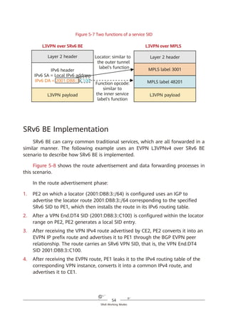
In L3VPN over MPLS scenarios, two MPLS labels are generally used: the outer
label directs packets to a specified PE, while the inner label functions as a service
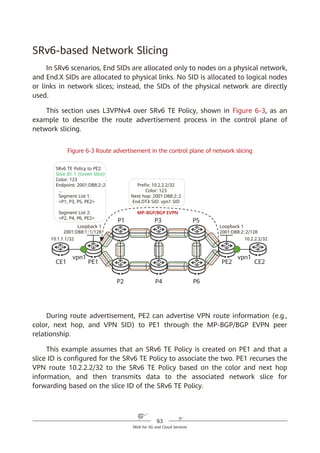
label to identify a VPN instance on the PE. In L3VPN over SRv6 BE scenarios,
however, only one SRv6 service SID is needed to implement the functions of both
MPLS labels. Take Figure 5-7 as an example, in which the service SID is
2001:DB8:3::C100 (locator: 2001:DB8:3::/64; function opcode: ::C100). The locator
2001:DB8:3::/64 is routable and can direct packets to the corresponding PE. The
function opcode ::C100 is a local function configured on the PE to identify services,
such as a VPN instance. The combination of the locator and function opcode parts
reflects that routing and MPLS (in which labels represent services) capabilities are
both integrated into SRv6 SIDs.
SRH (SL = n)
(SID [n]; SID [n – 1];
…
SID [1]; SID [0])
IPv6 Payload
IPv6 header
IPv6 SA = Local IPv6 address
IPv6 DA = SID [n]
Common SRv6 Packet Encapsulation
IPv6 Payload
IPv6 header
IPv6 SA = Local IPv6 address
IPv6 DA = Service SID
SRv6 BE Packet Encapsulation
(Without SRHs, Consistent with
Common IPv6 Packets)](https://image.slidesharecdn.com/ipv6srv6-240704021558-4ea0e87c/85/Technology-Tutorial-The-Basics-Of-IPv6-SRv6-59-320.jpg)
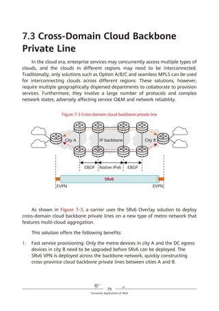
![67
SRv6 for 5G and Cloud Services
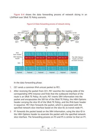
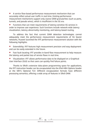
Figure 6-6 SRv6 iFIT encapsulation
All IPv6 forwarding nodes can process the iFIT instruction if it is encapsulated
into the HBH Options header, but only SRv6 nodes can process it if it is
encapsulated into the SRH. In SRv6 BE or SRv6 TE Policy loose path scenarios
where the packet forwarding path is not fixed, encapsulating the iFIT instruction
into the HBH Options header helps O&M personnel to know how packets are
forwarded hop by hop and facilitates fault demarcation when a fault occurs on
the network.
6.3 SRv6 for Telco Cloud
Telecom networks constructed in a traditional manner tightly integrate
software and hardware, using dedicated hardware devices purchased from device
vendors to provide telecom services. Such devices include Mobility Management
Entities (MMEs), Serving Gateways (SGWs), and Provisioning Gateways (PGWs)
for mobile data services and Broadband Network Gateways (BNGs) for fixed
services. But as telecom services (including emerging services like 5G) rapidly
develop, telecom networks need to respond quickly, adapt to diversified service
Arguments
Z
Locator Function
X Y
IPv6 SA IPv6 DA
Segment [0]
Segment [1]
…
Segment [n]
Optional TLV
SRH
IPv6 Header Format
IPv6 Header
HBH Options Header
Destination Options Header
Routing Header
Other Header
Upper-Layer Header
IPv6 Header Format
1
2
3
iFIT instruction header
encapsulation into the HBH
Options header
iFIT instruction header
encapsulation into the
Optional TLV of the SRH
Optional TLV
(App ID, user ID, App Req.)
App ID, user ID,
App Req.](https://image.slidesharecdn.com/ipv6srv6-240704021558-4ea0e87c/85/Technology-Tutorial-The-Basics-Of-IPv6-SRv6-73-320.jpg)