Downloaded 1,024 times
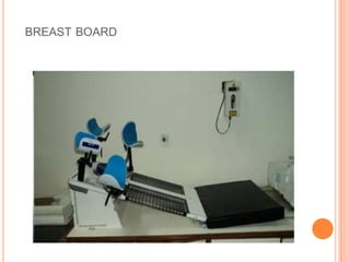
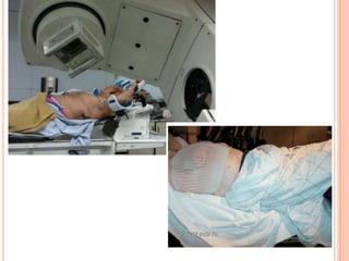
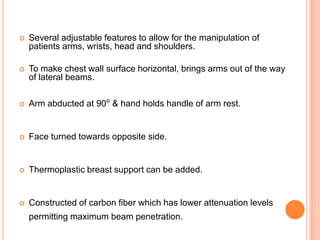
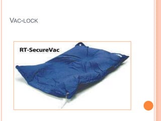
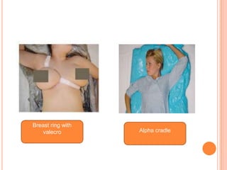

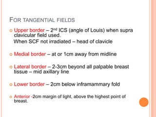
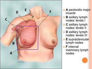
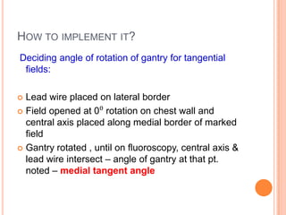
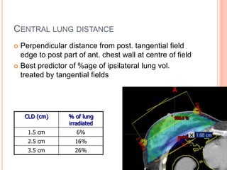
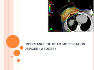
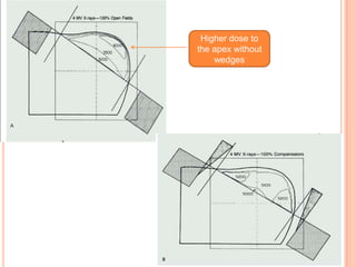


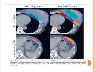
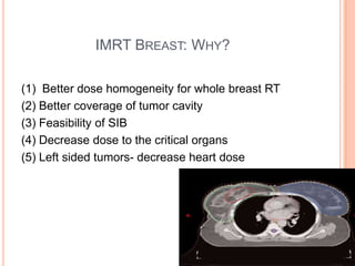
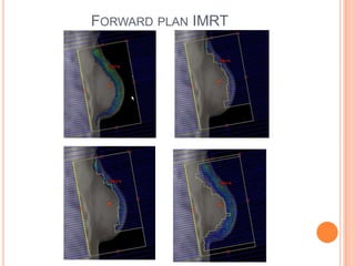
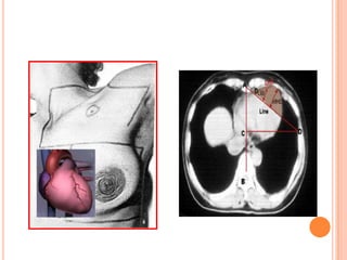


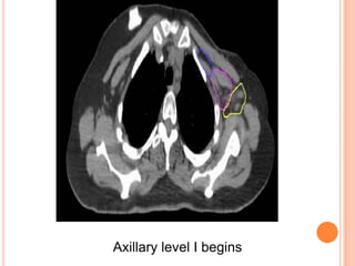
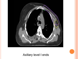
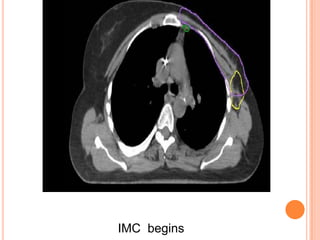
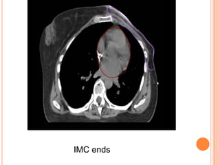


This document discusses technical issues in breast radiotherapy. It covers immobilization methods like breast boards and vac-locks to position patients. It describes how to determine field borders and angles for tangential fields. It also discusses treatment of regional lymph nodes like supraclavicular and internal mammary nodes. Techniques for breast conservation therapy like electron boosts and interstitial brachytherapy are covered. Guidelines for contouring regions like the breast and lymph nodes on CT scans are provided. The role of newer techniques like IMRT in breast radiotherapy is also summarized.


