Lathe machine
•Download as PPTX, PDF•
0 likes•1,568 views

See the classification of late, basic parts, lathe accessories, lathe operations

Recommended
More Related Content
What's hot
What's hot (20)
Similar to Lathe machine
Similar to Lathe machine (20)
Recently uploaded
Recently uploaded (20)
Lathe machine
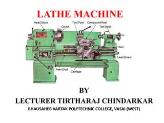
- 1. LATHE MACHINE BY LECTURER TIRTHARAJ CHINDARKAR BHAUSAHEB VARTAK POLYTECHNIC COLLEGE, VASAI (WEST)
- 2. DEFINITION • LATHE machine is a machine tool that is used to remove metals from a work piece to give a desired shape and size. • To cut the material properly the tool should be harder than the material of the work piece.
- 3. Q.1) State and explain the major factors considered for selection of cutting speed in lathe machine? • The type of material • Tool life and tool material • The dimensions of cutting tool • Surface finish required • The depth of cut • Rigidity of machine and work setup
- 4. Q.2) How lathe machines are Classified? 1. Speed lathe 2. Engine lathe 3. Bench lathe 4. Tool room lathe 5. Capstan and turret lathe 6. Special Purpose: a) Wheel lathe b) Gap bed lathe c) T- lathe d) Duplicating lathe 7. Automatic lathe 8.CNC lathe
- 5. SPECIFICATION OF CENTER LATHE A- Max. distance between centers B- Height of centers over bed C- Max. swing over carriage D- Max. swing over Bed E- Length of bed • Width of bed, headstock motor horse power, height of the lathe machine, overall dimensions of machine
- 6. Q.3) Basics Parts of Centre lathe and their Functions
- 7. • CENTRE LATHE: It is also called Engine lathe because the first of this type of lathe was driven steam engine. It has Two canters between which job is held and rotated. BASIC PARTS OF CENTRE LATHE: 1)Bed 2)Headstock 3)Tailstock 4)Carriage 5) Feed mechanism 6)Screw cutting mechanism 7) Main drive
- 8. THE BED: a) The lathe bed forms the base of the machine. b) It is the foundation of the machine and it holds all other parts of the lathe in their correct relative positions. C) Headstock and Tailstock located end of the bed. HEAD STOCK: a) The headstock is secured permanently on the inner ways at the left hand end of the lathe bed b) Its provides means of rotating the work at multiple speeds
- 9. TAIL STOCK a) Tail stock is located on the inner ways at the right hand end of the bed. b) It supports the other end of the work when it is being machined between centers. c) It hold a tool for performing operations such as drilling, reaming. Tapping, etc. CARRIAGE It serve to support , move and control the cutting tool. i)Saddle ii)cross-slide iii) Compound slide iv)Tool- post v)Apron
- 10. FEED MECHANISM a) The movement of the tool relative to the termed as “Feed”. b) When the tool moves parallel to the lathe axis, the movement is termed as longitudinal feed and is effected by movement of the carriage. c) When the tool moves at right angle to the lathe axis with the help of a cross slide the movement is termed as cross feed.
- 11. SCREW CUTTING MECHANISM The lead screw and the half nut mechanism are used to produce Screw thread MAIN DRIVE The primary motion is obtained by an electric motor that drives the spindle through a cone pulley system or through an all geared drive
- 12. LATHE ACCESSORIES • DEFINATION: Accessories of the a machine, are the devices which are used on the machine for the purpose of holding and supporting the work piece and tool. In other word, the accessories supports the machining operations. Some Important accessories (I) Chucks (II)Mandrels (III)Rests (IV)Face plates (V)Centers (VI)Angle plates
- 13. CHUCKS Chucks hold and rotates the job with the help of its adjustable Jaws. It is basically screwed or threaded to the headstock spindle. Types of CHUCKS: a) Three Jaw chuck or universal chuck b) Four Jaw independent chuck c) Magnetic chuck
- 14. A) THREE JAW CHUCK OR UNIVERSAL CHUCK • It is used to hold round and hexagonal work • Made in common size Approx. 100 to 400 mm in diameter • The movement of Three Jaws take place at the time • It is also known as Self Centered Jaw chuck
- 15. B) FOUR JAW CHUCK • The arrangement of four jaws independent chuck, which has four jaws, located at an angle of 90° to each other. • Each jaw made of tough steel has three inner and one outer gripping surface
- 16. C) MAGNETIC CHUCK • The chuck is used for holding a very thin work piece made of magnetic material which cannot be held in an ordinarily chuck • The holding power of the chuck is obtained by the magnetic flux radiating either from the electromagnets or from the permanent magnets introduced within the chuck.
- 17. MANDRELS Lathe mandrels are devices used to hold for job machining on lathes. It has 600 centers on both sides and it holds and locate a part from its center hole Mandrels are used for turning of bushes, gear blanks, pulleys etc.
- 18. RESTS Rests are the devices used to support lengthy or long work piece which are held between the centers to prevent the bending of job The job may bend during turning because of its weight And cutting forces. Two types of rests are commonly used : I) Steady test II) Follower test
- 19. FACE PLATE • It is round disk which has a threads inside the bore to fit on to the nose of the spindle. • It is specially used for those jobs which are heavy, too large and or uneven in shape.
- 21. ANGLE PLATE • An angle plate is a precision L-shaped piece which both faces are machined 900 to each other with greater accuracy. • It is made up of cast iron or Hardened steel. • It has slots and holes cuts on its both faces used for clamping the work by means of bolts and clamps
- 22. LATHE OPERATIONS Q.1) STATE THE VARIOUS OPERATIONS PERFORMED ON THE LATHE. EXPLAIN ANY TWO IN BRIEF. 1) Turning :- a)Straight b)Step c) Taper 2) Facing 3) Thread cutting 4) Knurling 5) Drilling 6) Boring 7) Parting off 8) Grooving 9) Chamfering
- 23. 1] TURNING • A machining process in which a single-point tool material from the surface of a rotating work piece a) Straight Turning b)Step turning
- 24. C) Taper Turning: • Taper turning as a machining operation is the gradual reduction in diameter from one part of a cylindrical work piece to another part.
- 25. Taper Turning Methods • In lathe, the taper can be turned by any one of the following methods i)Swiveling of the compound rest ii) Setting over the tailstock center iii)By using broad nose form tool iv)By a taper turning attachment
- 26. i)Swiveling of the compound rest tan α = (D-d)/2L Where D and d are large And small dia. & L is length ii) Setting over the Tailstock Center sin α = BC/AB
- 27. iii)Broad nose form tool iv)Taper Turning Attachment
- 28. 2] FACING 3] THREAD CUTTING 4] KNURLING 5] DRILLING
- 29. 6] BORING 7] PARTING OFF 8] GROOVING 9] CHAMFERING
- 30. DIFFERENCE BETWEEN ORTHOGONAL AND OBLIQUE CUTTING SR NO. ORTHOGOANAL CUTTING OBLIQUE CUTTING 1 Tool cutting edge make 90° with path of movement of tool Tool cutting edge makes angle other than 90° with tool line of action 2 2-dimensional cutting 3-dimensional 3 Tool life shorter longer tool life 4 Analysis is simple Analysis is complex 5 Two mutually perpendicular cutting forces act on the work piece Two mutually perpendicular cutting forces act on the work piece 6 More heat generated for the same amount of work Less heat generated for the same amount of work 7 Limited application Wide application 8 It removes less metal during its life It removes more metal in the same life of orthogonal cutting tools