Downloaded 132 times

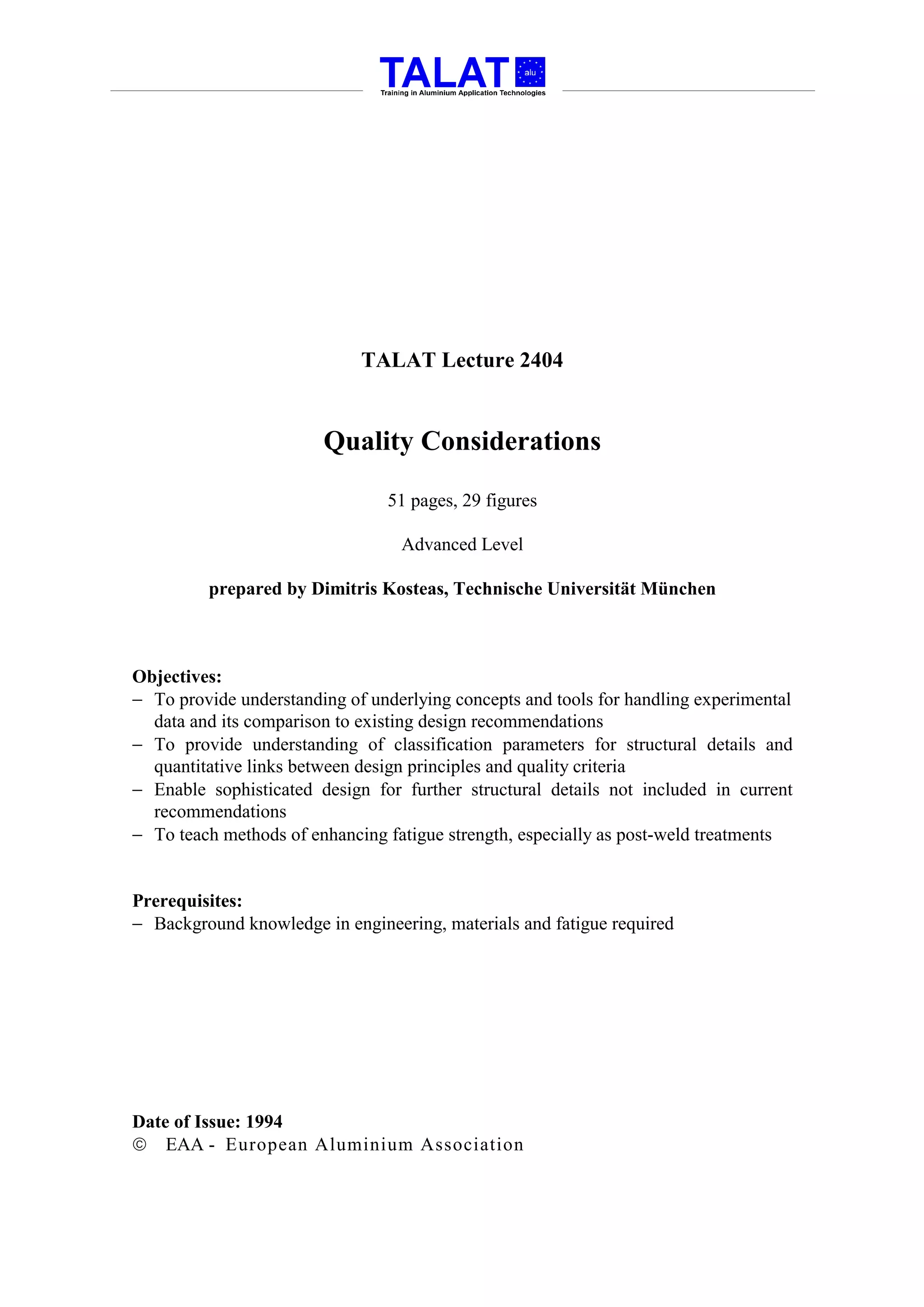
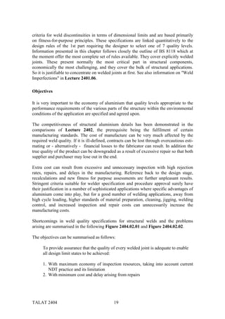
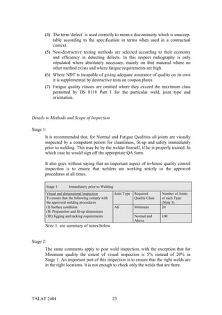
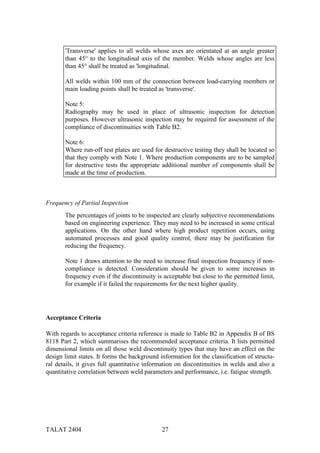
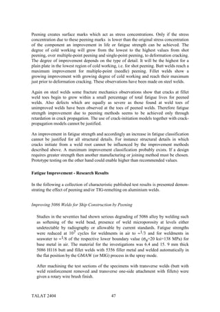
![Fatigue Test Data Format
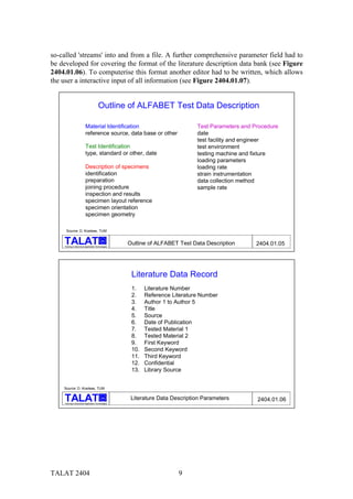
Material Identification Test Parameters and Procedures Test Results and Analysis
reference source, date no. of specimens
data base or other test facility and engineer rate of loading
test environment loading parameters
Test identification testing machine and fixture loading statistical data
type, standard or other, date loading parameters mechanical parameters
loading rate physical parameters
Description of specimens strain instrumentation strength or/and strain
identification
data collection method nominal, average
preparation
sample rate standard deviation, coefficient
joining procedure
failure location
inspection and results
failure mode
specimen layout reference
test validation, data quality
specimen orientation
raw test data source
specimen geometry
remarks, if any, such as
significant deviation
from standard
Source: D. Kosteas, TUM
alu
Training in Aluminium Application Technologies
Fatigue Test Data Format 2404.01.02
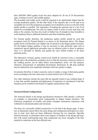
As will be seen in the following, several of these suggestions have already been taken
into account and have been incorporated in the format of the Aluminium Data Bank.
Early Developments
First decisive steps in the computerisation of fatigue test results in the form of a data
bank for aluminium can be traced back to initial work by Munse followed by efforts by
Sanders around 1970 who started the Welding Research Council Aluminium Data Bank
at Iowa State University [1]. Data were initially stored on punched cards.
Regressional analysis software was developed in the late sixties by Kosteas at the Uni-
versity of Karlsruhe [2] and applied thereafter on consecutive comprehensive
evaluations on aluminium fatigue test data. A cooperation was initiated in the early
eighties under the Committee on Aluminum Fatigue Data Exchange and Evaluation
(CAFDEE) [3] resulting since 1985 in a simultaneous installation and operation of the
Aluminium Data Bank at the Iowa State University and the Technical University of Mu-
nich.
One of the primary tasks of the last years has been the user-oriented adaptation of avail-
able aluminium test data and software for its evaluation, whereby the former main frame
computer operation has been abandoned in favour of the now broadly available personal
computers.
The logical extension and applicability in engineering design led to the concept of a ma-
nagement system for such material, technological, manufacturing, quality control and
TALAT 2404 5](https://image.slidesharecdn.com/talat-lecture-2404-quality-considerations1391/85/TALAT-Lecture-2404-Quality-Considerations-5-320.jpg)
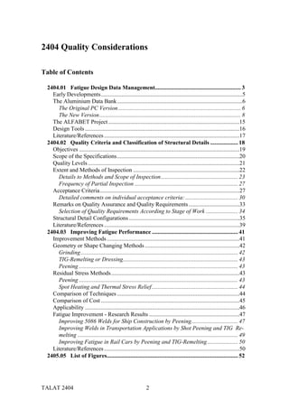
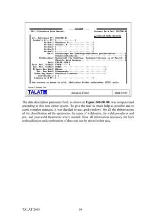
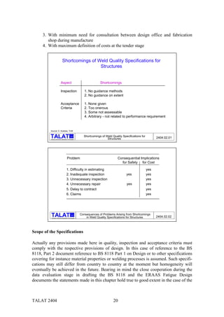
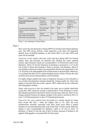
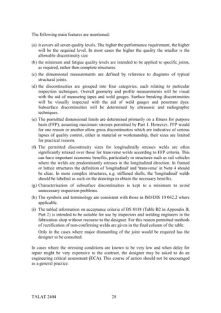
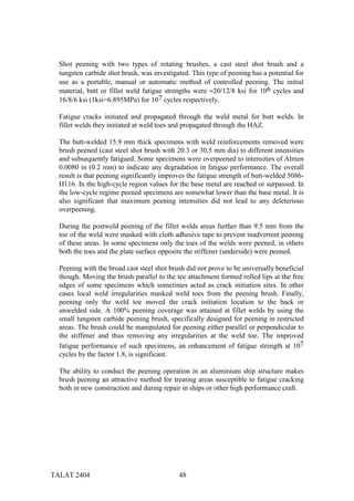
![reliability information and processes as needed during the design procedure of alumini-
um constructions, Figure 2404.01.03.
ALFABET
Expert System
Aluminium Data Bank
Fatigue of
Aluminium Structures
Design Assessment Production
Reliability Literature
Fitness-for-Purpose Expert Knowledge
Interface
to the
User
Source: D. Kosteas, TUM
alu
Training in Aluminium Application Technologies
Data Management- ALFABET Expert System 2404.01.03
The first task is complete by now and consists of what is understood as the Aluminium
Data Bank (ALDABA). The bank is itself a part of the second more comprehensive task,
the Aluminium Fatigue Behaviour Evaluation Task (ALFABET) Project. These two are
described in more detail in the following chapters.
The Aluminium Data Bank
The Original PC Version
In the first stage of the data bank, from 1987 to 1989, the use of commercially available
software was favoured since development and employment had to be performed in par-
allel. Extensive analyses, significant to drafting the ECCS European Recommendations
for fatigue design in aluminium, were carried out [4]. This work was invaluable in test-
ing procedures and providing decisions for future applications.
The data bank management was based on the dBase III+ software package. A positive
fact was the rather powerful structured query language (SQL) for data retrieval and sel-
ection. However concerning the user menu, graphics, colours or hardware programming
we were confronted by serious handicaps. In order to circumvent licence problems with
directly applicable programmes, i.e. *.EXE or *.COM files, dBase programme run-
TALAT 2404 6](https://image.slidesharecdn.com/talat-lecture-2404-quality-considerations1391/85/TALAT-Lecture-2404-Quality-Considerations-6-320.jpg)
![versions were constructed by means of the compiler system "Clipper". Available data
was stored in three parts:
(a) the literature data bank,
(b)the detail and data description data bank, and
(c) the fatigue test data points themselves and their mathematical processing.
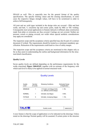
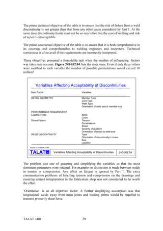
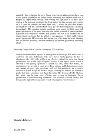
Parts (a) and (b) were written in dBase III+, whereby the rather complex statistical for-
mulas of part (c) were executed in Pascal - all parts integrated to one programme by
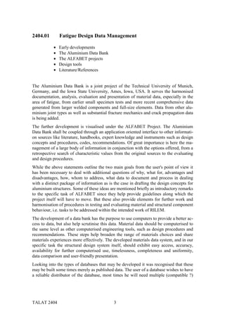
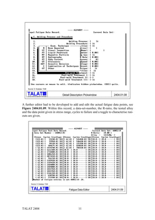
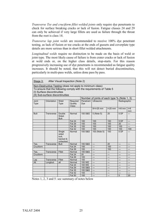
means of "Clipper". Part (b) is essential to the user since it allows data set selection and
detail classification. A comprehensive parameter field has been covered by the format of
the detail description data bank, see Figure 2404.01.04.
A. General D. Welding Process and Procedure E. Base Material
1. Data Set No. 1. Welding Process 1. Alloy Designation (4 Letter AA Designation)
2. Literature No. 2. Welding Procedure 2. Temper or Heat Treatment
3. Page No., Table No., etc. 3. Welding Position 3. Product Name or National Designation
4. Test Year (19__) 4. Filler Material (4 Letter AA) 4. Fabricator
5. Confidential (Y/N) 5. Filler Material (Product Name) 5. Product Form
6. Last Check (dd/mm/yy) 6. Welding Wire Diameter (mm) 6. Chemical Composition
7. Remarks 7. Shielding Gas 7. Tested Yield Strength (MPa)
8. Shielding Gas Flow Rate (l/min) 8. Yield Point Off-Set (%)
B. Joint Description 9. No. of Passes 9. Tested Ultimate Strength (MPa)
1. Basic Weld Type 10. Welding Speed (cm/min) 10. Ultimate Strain (%)
2. Edge Preparation 11. Welding Current (Ampere)
3. Weld Geometry 12. Welding Voltage (Volts) F. Test Conditions
Joint Dimensions 13. Non-destructive Examination 1. Test Machine
4. R (mm) Technique 2. Mode of Loading
5. F (mm) 14. Discontinuities 3. Orientation of Weld and Load
6. p (degrees) 15. Pre-Weld Treatment 4. Environmental Conditions
7. H (mm) 16. Post-weld Treatment I 5. Type of Loading
8. D (mm) (Notch Shape Modification Methods) 6. Temperature (°C)
17. Post-weld Treatment II 7. Frequency (Hz)
C. Specimen Description
(Mechanical Treatments) 8. Failure Criteria
1. Specimen Description
18. Post-weld Treatment III 9. Basis of Recorded Stress or Strain
2. Thickness (mm)
(Thermal Methods) 10. R-Ratio
3. Width (mm)
4. Tested Yield Strength (MPa) 11. Number of Stress Levels
5. Yield Point Off-Set (%) 12. Number of Data Points
6. Tested Ultimate Strength (MPa)
7. Ultimate Strain (%)
8. Gage Length (mm)
Source: D. Kosteas, TUM
alu
Test Data Description Parameters 2404.01.04
Training in Aluminium Application Technologies
The data bank primarily covered fatigue test data of various alloys in structural enginee-
ring applications (alloy groups 5xxx, 6xxx and 7xxx), base material and numerous wel-
ded joint types. The original CAFDEE data bank included approx. 15000 data points on
small specimens, which have now been to a large extend re-checked and validated.
Though interesting in many ways these older data on small specimens presented pro-
blems regarding the capability to lead to reliable conclusions [5]. There were serious
gaps in the documentation, even of geometrical or welding and, at times, testing para-
meters. Beyond this, small specimen data will not reflect actual component behaviour in
service. These facts have been widely acknowledged and led to decisions about 10 years
ago in the area of aluminium constructions for experimental research in fatigue and
eventually for evaluating carefully performed observations mainly on large components.
TALAT 2404 7](https://image.slidesharecdn.com/talat-lecture-2404-quality-considerations1391/85/TALAT-Lecture-2404-Quality-Considerations-7-320.jpg)
![In the course of these comprehensive fatigue test series at the Technical University of
Munich between 1982 and 1990 a nucleus of approx. 1,000 extensively documented and
published data points on large structural components, beams, have been generated. Fur-
ther fatigue tests performed by industry on components and made available during the
recent recommendations drafting process [6] will hopefully become publicly available in
the near future. These, together with recent work performed by Fisher and Menzemer,
will increase the contingent to more than 2,500 data points. It should also be mentioned
that in the course of the last years' evaluation almost another 20,000 data points on small
specimens provided by industry [6] served in drafting the European Recommendations
[7, 8].
The New Version
A user-friendly data bank, allowing ready access to information and compatibility to all
other steps in the structural design procedures, should enable a simple, logical and relia-
ble dialogue with the user. This led to a menu-driven programme with controls against
unintended input errors.
Consequently the decision was made in 1989 to choose the latest Turbo-Pascal version
5.5 as the new programming language (this being at that time the only language allow-
ing object-oriented-programming). Another advantage for the user was reached by using
the much more rapid and reliable BIOS system to control input/output functions and
thus avoiding any harmonisation problems with other programmes.
A basic feature in this new version is the main menu, guiding the user through the whole
programme. An object-oriented window and menu management system had to be de-
veloped with simple mouse- or key-driven selection of programme functions. In a dialo-
gue with the user, further information may have to be supplied and its plausibility
checked immediately. Common compilers on the market did not offer such language ca-
pacities, so that all tools were written in assembler language, guaranteeing maximum
control of the hardware combined with maximum of operation speed.
In the last two years the statistical/regression data part of the bank, as well as the data in-
formation and data set description parts of the system was finished for mouse-supported
operation. The main menu appears on the screen, when typing "ALF.EXE", which out-
lines the capacities of the programme. The division into three main parts is established
through the menu points 'Literature Data', 'Data Description' and 'Fatigue Test Data' (see
Figure 2404.01.05).
Programming languages are planned to be flexible and open for each area, so normally
these languages provide no special features for screen or file handling. Pascal, as such a
programming code, offers no special routines for generating menus or other features. All
had to be developed and tested in first place. The aim was to give the whole system a
unique and simple outlook and operating capacity. Turbo-Pascal allows only a very
simple file handling, so further new tools had to be developed for writing and reading
TALAT 2404 8](https://image.slidesharecdn.com/talat-lecture-2404-quality-considerations1391/85/TALAT-Lecture-2404-Quality-Considerations-8-320.jpg)
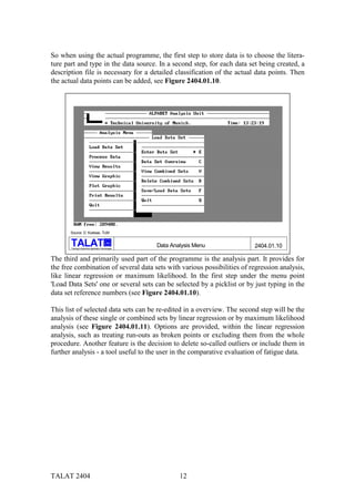
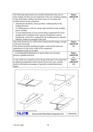
![− further component test data in currently performed fatigue tests in Europe and
USA,
− data as given in Japanese literature,
− validation of component test data as outlined in [9],
− comprehensive fracture mechanics properties data for aluminium alloys
currently being recorded at the TUM, and
− extensive crack propagation test data generated by Jaccard [10] or Graf and
Kosteas [11,12] at the TUM in the early eighties for base material, weld metal
and HAZ material of different aluminium alloys and weldments under
variation of stress ratio and plate thickness.
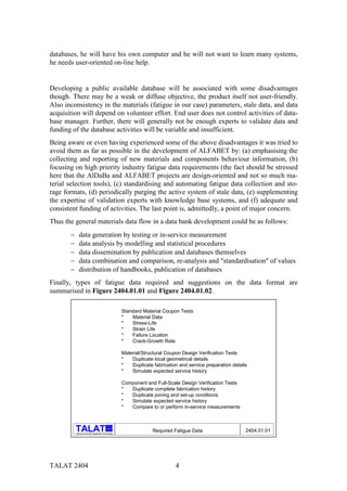
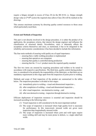
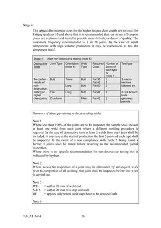
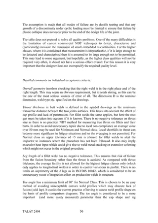
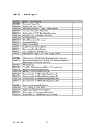
A. Rough goal definition Expert System for static and fatigue design formulation of application
B. Initial Information Accumulation 1. Literature survey and compilation
(largely unstructured in this place) 2. Information from practice
3. Definitions
4. Documentation of standard recommendations etc.
cross section references to other documents
design and manufacturing rules
5. quality criteria
Fitness for Purpose, NDT, Detail Classification
6. Available software
Drafting Software
C. Knowledge Presentation Accumulated documentation material to be structured, ordered and presented
in an abstract and universal format
D. Main Information Accumulation Application oriented, enhanced documentation
E. Pilot or Prototype study Performed for a number of case-studies
Check ES format, alter, amend, re-check (Iteration)
F. Detailed Study ES integration in actual working format
G. System Development ES adaptation after D
H. Check and Validation Phase Actual design cases compared to ES solution
I. Installation and Acceptance Phase Efficiency in industrial application
J. Maintenance and Updating
Source: D. Kosteas, TUM
alu
Training in Aluminium Application Technologies
Development Stages of the Expert Design System 2404.01.14
Design Tools
A first item has been produced by the Technical University of Munich, the "Classifica-
tion and Design of Fatigue Loaded Aluminium Constructions" as a computerised ver-
sion of the "ERAAS Fatigue Design" rules. It comprises of a complete manual of the
recommendations, quick cross-references, a structural detail unit with full descriptions,
a survey menu for the selection of details and a complete design menu featuring all sig-
nificant spectrum input and performing the final fatigue assessment.
A demonstration of its application is given with the fatigue assessment calculation
example in Lecture 2402.
TALAT 2404 16](https://image.slidesharecdn.com/talat-lecture-2404-quality-considerations1391/85/TALAT-Lecture-2404-Quality-Considerations-16-320.jpg)
![Literature/References
[1] Sanders W. W., Jr. and Day R. H.: „Fatigue Behaviour of Aluminum Alloy
Weldments“. WRC-Bulletin 286, Welding Research Council, New York,
August 1983
[2] Steinhard O. und Kosteas D.: „Die Schwingfestigkeit geschweißter
Aluminiumverbindungen aus der Sicht optimierter
Lebensdauerfunktionen“. Mitteilungen der Versuchsanstalt Stahl, Holz
und Steine der Universität Karlsruhe, Reihe 3, Heft 5, 1971
[3] Kosteas D., Kirou J., Sanders W. W., Jr.: „Fatigue Behaviour of Aluminium Alloy
Weldments - A CAFDEE Report“. Vol. 1 to Vol. 4, Eng.Res.Inst., Iowa
State University, Ames, 1986
[4] Kosteas D., Uhry A.: „Fatigue Behaviour of Aluminium Structures - European
Full Scale Tests“. CEC-COST 506 - EAA, Parts 2 to 3, Munich/Voreppe
1989
[5] Kosteas D.: „Influence of Residual Stresses on S-N Curve Parameters of
Aluminium Weldments“. IIW-Doc XIII - 1239 - 87
[6] Jaccard R.: „Unpublished Internal Reports and Materials“. Provided by Alusuisse,
Zürich/Switzerland for the EAA ECCS Fatigue Workshops Munich and
Zürich
[7] Kosteas D.: „European Recommendations for Fatigue Design of Aluminium
Structures“. Proc. International Conference for Aluminium Weldments,
5th INALCO ‘92, Munich 27-29 April 1992
[8] Sanders W. W., Jr., Maddox S. J., Kosteas D.: „Aluminium Fatigue Data -
Description and Principles for Evaluation“. Proc. International
Conference for Aluminium Weldments, 2nd INALCO ‘82, Munich May
1982
[9] Kosteas D.: „Contemplation on the ERAAS Fatigue, a State-of-the-Art of
Developments“. ECCS Doc. 28.05.1986.
[10] Jaccard R.: „Einführung in die Bruchmechanik - Der Ermüdungsbruch“.
Seminarreihe der Aluminium-Zentrale e.V., 12-13 September 1990,
Meckenheim
[11] Graf U.: „Ermittlung der Kennwerte für den Ermüdungsrißfortschritt“.
Seminarreihe der Aluminium-Zentrale e.V., 12-13 September 1990,
Meckenheim
[12] Graf U.: Bruchmechanische Verfahren bei Aluminiumbauteilen“. Dissertation an
der TU München in Berichten aus dem Konstruktiven Ingenieurbau,
München 1992
TALAT 2404 17](https://image.slidesharecdn.com/talat-lecture-2404-quality-considerations1391/85/TALAT-Lecture-2404-Quality-Considerations-17-320.jpg)
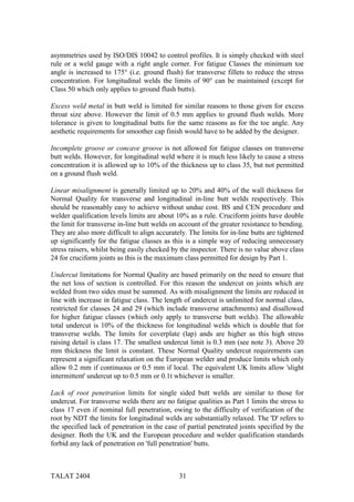
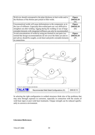
![Improving Welds in Transportation Applications by Shot Peening and TIG
Re-melting
Following an earlier study on the influence of shot peening on welded aluminium
alloys such as 5086, 6082, and 7020, and the general statement of 80% improvement
upon fatigue behaviour due to peening, a more detailed recent study in France has
undertaken the task to define the improvement in fatigue for shot-peened 5086-H111
butt and fillet welds. The fillet welded cruciform joints in 6 mm thickness were
welded (a) without any edge preparation and (b) with a groove preparation. In case
(a) peening effects on a weld with internal defects could be studied. An automatic
MIG process with 5356 filler metal was used.
The shot peening was undertaken with three different kinds of shot/ dia [µm]/ Almen
intensity French Standard: glass/300/F10N-F30N, ceramic/425/F20A-F25A, mild
steel/800/F45A-F50A. Induced residual stresses were recorded by X-ray diffraction.
They reached a value at the surface depending on the shot, 150/120/80 MPa for
glass/ceramic/steel. The maximum stress value was with 200 MPa the same for the
three cases as related to the mechanical properties of the alloy itself. The depth of the
maximum was at 20/80/200 µm and the depth affected by shot peening was
300/600/1000 µm for glass/ceramic/steel.
Specimens were fatigued at R = +0.1 at a frequency of 100 Hz and maxσ = 90 MPa.
The same value was adopted for both butt and fillet welds on the experience that an
one-side butt weld has a lower fatigue strength than a double-side butt weld and
similar to the strength of a fillet weld.
Comparing results at the 90 MPa level for the butt weld it may be stated that shot
peening with glass had a slight improvement upon life, but ceramic or steel improved
life by a factor of 15 over the values for untreated specimens. A maximum
improvement is reached for a depth of ≈ 600 µm, beyond this value no further
improvement is obtained. The greater depth reached with steel shot did not contribute
thus to any further improvement and it must be noted that the shot diameter with 800
µm may have been the cause of detrimental effects, reducing the overall positive
influence of shot peening. For practical applications a diameter of 400 µm is
recommended. Fatigue cracks initiated on the surface, at weld toes or in zones with
undercut. The life enhancement from shot peening is obvious.
Analogous comparisons can be drawn for the fillet welds. Naturally all results for
specimens with a groove preparation were better than those without edge preparation.
At joints with a groove preparation cracks initiated again most probably at weld toes
on the specimen surface. The life improvement was ≈10 times in relation to
respective unpeened specimens and it was greatest for the glass or steel shot and
somewhat lower for the ceramic shot.
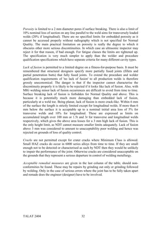
Fillet welds without a groove preparation exhibited a crack initiation in the weld
when unpeened and when shot peened a fracture at half depth (weld root?)
propagating to the outer surface before any crack initiation from the outside could be
TALAT 2404 49](https://image.slidesharecdn.com/talat-lecture-2404-quality-considerations1391/85/TALAT-Lecture-2404-Quality-Considerations-49-320.jpg)
![[1] N.N.: European Recommendations for Aluminium Alloy Structures-Fatigue
Design. ECCS Doc. 68, Brussels 1992
[2] N.N.: BS 8118. Structural Use of Aluminium. Part 1: Design, Part 2:
Workmanship. BSI 1991
[3] Bremen, I.F.C. Smith and W.J. Muster: Erhöhung der Ermüdungsfestigkeit
Geschweißter Verbindungen. Publication ICOM 131, EPFLausanne,
September 1984
[4] Smith, V. Dubois and U. Bremen: Peening Methods for Improvement of Fatigue
Strength. Publication ICOM 230, EPFLausanne, February 1990
[5] Montemarano and M.E. Wells: Improving the Fatigue Performance of Welded
Aluminum Alloys. Welding Journal, June 1980
[6] Albert, S. Bompard, M. Bramat and L. Castex: Shot Peening Effect on Fatigue
Behaviour of Aluminium Welded Joints. In: Proceedings 5th INALCO
1992, ed. D. Kosteas, R. Ondra and F. Ostermann. Munich, April 1992,
pp. 2.1.1 to 20
[7] Polmear: Post-Weld Surface Treatments to Improve Fatigue Properties of
Aluminium Weldments. Australian Welding Research, December 1985,
pp. 64 to 68
TALAT 2404 51](https://image.slidesharecdn.com/talat-lecture-2404-quality-considerations1391/85/TALAT-Lecture-2404-Quality-Considerations-51-320.jpg)

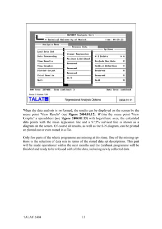
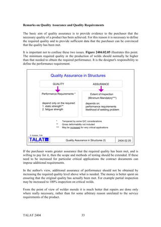
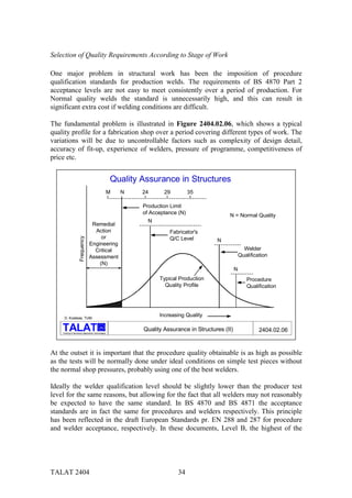
The document outlines advanced quality considerations in fatigue design for aluminium structures, focusing on data management, quality criteria, and methods to improve fatigue performance. It describes the development of the Aluminium Data Bank, which compiles and analyzes fatigue data, detailing its objectives, structure, and the evolution of software used for data management. Additionally, it emphasizes the importance of user-friendly access to material data for effective engineering design and quality assurance.


