Taiyi fiber laser marking machine manual english edition
•
1 like•350 views

Described how to operate this machine and how to set software parameters and equipment maintenance.Taiyi laser copyright

More Related Content
What's hot
What's hot (20)
Similar to Taiyi fiber laser marking machine manual english edition
Similar to Taiyi fiber laser marking machine manual english edition (20)
Recently uploaded
Recently uploaded (7)
Taiyi fiber laser marking machine manual english edition
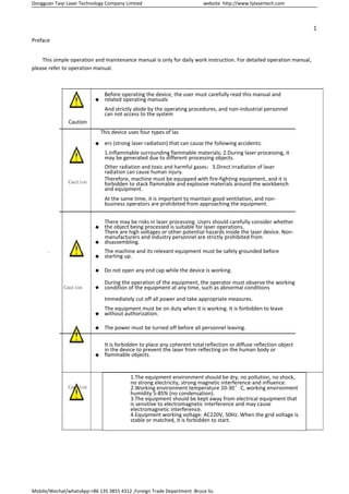
- 1. Dongguan Taiyi Laser Technology Company Limtied website http://www.tylasertech.com Mobile/Wechat/whatsApp:+86 135 3855 4312 ,Foreign Trade Department :Bruce liu 1 Preface This simple operation and maintenance manual is only for daily work instruction. For detailed operation manual, please refer to operation manual. 。 Before operating the device, the user must carefully read this manual and related operating manuals Caution And strictly abide by the operating procedures, and non-industrial personnel can not access to the system This device uses four types of las ers (strong laser radiation) that can cause the following accidents: 1.Inflammable surrounding flammable materials; 2.During laser processing, it may be generated due to different processing objects. Caution Other radiation and toxic and harmful gases;3.Direct irradiation of laser radiation can cause human injury. Therefore, machine must be equipped with fire-fighting equipment, and it is forbidden to stack flammable and explosive materials around the workbench and equipment. At the same time, it is important to maintain good ventilation, and non- business operators are prohibited from approaching the equipment. There may be risks in laser processing. Users should carefully consider whether the object being processed is suitable for laser operations. There are high voltages or other potential hazards inside the laser device. Non- manufacturers and industry personnel are strictly prohibited from disassembling. The machine and its relevant equipment must be safely grounded before starting up. Do not open any end cap while the device is working. Caution During the operation of the equipment, the operator must observe the working condition of the equipment at any time, such as abnormal conditions Immediately cut off all power and take appropriate measures. The equipment must be on duty when it is working. It is forbidden to leave without authorization. The power must be turned off before all personnel leaving. It is forbidden to place any coherent total reflection or diffuse reflection object in the device to prevent the laser from reflecting on the human body or flammable objects. Caution 1.The equipment environment should be dry, no pollution, no shock, no strong electricity, strong magnetic interference and influence. 2.Working environment temperature 10-30°C, working environment humidity 5-85% (no condensation). 3.The equipment should be kept away from electrical equipment that is sensitive to electromagnetic interference and may cause electromagnetic interference. 4.Equipment working voltage: AC220V, 50Hz. When the grid voltage is stable or matched, it is forbidden to start.
- 2. Dongguan Taiyi Laser Technology Company Limtied website http://www.tylasertech.com Mobile/Wechat/whatsApp:+86 135 3855 4312 ,Foreign Trade Department :Bruce liu 2 Contents Chapter one Equipment composition..................................................................................................................... 1 1.1 Hosts................................................................................................................................................................1 Chapter two Operating Equipment...........................................................................................................................2 2.1 Device control panel.................................................................................................................................... 2 2.2 Start the power............................................................................................................................................2 2.3 Start the laser source power...................................................................................................................... 2 2.4 Launch laser marking software.................................................................................................................. 3 2.4.1 File import and open........................................................................................................................4 2.4.2 Perform processing..........................................................................................................................4 Chapter three Device Parameter Settings............................................................................................................... 5 3.1 Laser operating parameter settings................................................................................................................5 3.1.1 Q SWITCH pulsed fiber laser setup.....................................................................................................5 3.1.2 Mopa pulsed fiber laser setup....................................................................................................... 5 3.2 Layer parameter settings............................................................................................................................ 6 3.3 Rotary marking parameter setting with zero return function (optional)....................................................... 8 3.3.1 Segmentation mark ...........................................................................................................................8 3.3.2 Rotation angle marking................................................................................................................... 9 3.3.3 Rotating text mark............................................................................................................................ 10 Chapter 4 Equipment Commissioning....................................................................................................................11 4.1 Focus debugging............................................................................................................................................11 4.1.1 Working distance setting..............................................................................................................11 4.1.2 Software marking range setting....................................................................................................... 12 4.1.3 Focal length adjustment....................................................................................................................12 4.2 Mirror correction........................................................................................................................................13 4.2.1 Preparation before correction.....................................................................................................13 4.2.2 Calibration process........................................................................................................................... 13 4.3 Red light indicator......................................................................................................................................... 14 4.4 Foot switch....................................................................................................................................................14 Chapter five Turn off the device..................................................................................................................15 Chapter six Equipment Maintenance..................................................................................................................... 16 6.1 Host............................................................................................................................................................... 16 6.1.1 Working table....................................................................................................................................16 6.1.2 Optical scanning field lens............................................................................................................16 6.2 Maintenance list
- 3. Dongguan Taiyi Laser Technology Company Limtied website http://www.tylasertech.com Mobile/Wechat/whatsApp:+86 135 3855 4312 ,Foreign Trade Department :Bruce liu 1 Chapter 1 This equipment consists of host, mechanical system, control system, optical system and other components. 1.1 Host Manual Scanning galvanometer and field lens Laser, galvanometer, red light, key switch Master switch
- 4. Dongguan Taiyi Laser Technology Company Limtied website http://www.tylasertech.com Mobile/Wechat/whatsApp:+86 135 3855 4312 ,Foreign Trade Department :Bruce liu 2 Chapter 2 Operating Equipment 2.1 Device control panel 2.2 Start the main power 2.3 Start the laser power From right to left, press the master switch, red switch, galvanometer switch, and laser switch.
- 5. Dongguan Taiyi Laser Technology Company Limtied website http://www.tylasertech.com Mobile/Wechat/whatsApp:+86 135 3855 4312 ,Foreign Trade Department :Bruce liu 3 2.4 Start laser marking software After installation finished it will be displayed on the desktop,Double-click the mouse to start the software. The main interface of the software is as follows:
- 6. Dongguan Taiyi Laser Technology Company Limtied website http://www.tylasertech.com Mobile/Wechat/whatsApp:+86 135 3855 4312 ,Foreign Trade Department :Bruce liu 4 2.4.1 File import and open Ezcad2 supports the import of vector format not bitmap format: Bitmap format: Supports BMP, JPG, PNG, GIF, etc. Vector Format: Supports PLT, AI, DXF, etc. Ezcad2 software supports opening EZD format: 2.4.2 Perform processing Press on the keyboard F2
- 7. Dongguan Taiyi Laser Technology Company Limtied website http://www.tylasertech.com Mobile/Wechat/whatsApp:+86 135 3855 4312 ,Foreign Trade Department :Bruce liu 5 Chapter 3 Device Parameter Settings In order to make better use of the Rainbow series optical fiber marking machine, the highest efficiency of the device is achieved. The device parameter settings in the software will be explained below. 3.1 Laser source parameter settings 3.1.1 Q SWITCH Pulsed fiber laser setup. Open the Ezcad2 Marking Software and click the Parameters (Keyboard F3) button to enter the configuration parameter settings. The laser type in the system is fiber. The laser frequency range is 20~80KHz. Fiber type IPG_YLP is selected and Mo delay is 8ms. 3.1.2 Mopa Pulsed fiber laser setup. Open the Ezcad2 Marking Software and click the Parameters (Keyboard F3) button to enter the configuration parameter settings.
- 8. Dongguan Taiyi Laser Technology Company Limtied website http://www.tylasertech.com Mobile/Wechat/whatsApp:+86 135 3855 4312 ,Foreign Trade Department :Bruce liu 6 The laser type in the system is fiber, and the laser frequency range is 20~1000KHz. Select IPG_YLPM for Fiber type, and enable Mo delay for 8ms. Check the enable pulse width setting 3.2 Layer parameter settings In the Ezcad2 main interface, the laser layer parameters are as follows:
- 9. Dongguan Taiyi Laser Technology Company Limtied website http://www.tylasertech.com Mobile/Wechat/whatsApp:+86 135 3855 4312 ,Foreign Trade Department :Bruce liu Q Switch Laser source settings Mopa Laser source settings The meaning of the parameters:
- 10. Dongguan Taiyi Laser Technology Company Limtied website http://www.tylasertech.com Mobile/Wechat/whatsApp:+86 135 3855 4312 ,Foreign Trade Department :Bruce liu 7 Parameter Setting range Instructions Speed (mm/s) 1~4000 power(%) 1-100 frequency(KHz) 20~80/45-500 Q Switch/ Mopa Opening delay (Microseconds) -50~-200 Off laser delay(Microseconds) 50-200 Close delay(Microseconds) 50-200 Close delay>Off laser delay Corner delay(Microseconds) 1-150 Mopa fiber laser with pulse width modulation. Different pulse widths, frequencies and powers can be selected according to different materials and marking applications. Decrease power frequency refers to: When the set frequency is lower than the deceleration frequency, the actual output power of the laser will be reduced by a certain factor; and if the set frequency is higher than or equal to the deceleration frequency, the output power will not reduce the normal output. For example, using 200ns/45KHz/100% output power is 20W, when using 200nS/23KHz/100%, the actual output power is about 10W; when using 200nS/40KHz/100%, the actual output power is about 17.8W; using 200ns/ The actual output power is about 20W at 46KHz/100%. Q Pulse Width Decrease power frequency
- 11. Dongguan Taiyi Laser Technology Company Limtied website http://www.tylasertech.com Mobile/Wechat/whatsApp:+86 135 3855 4312 ,Foreign Trade Department :Bruce liu 8 3.3 The parameter setting of the rotary marking with the function of returning to origin.(optional) Rotary dial stepping motor Angle adjustment nut 3.3.1 Segmentation marking 2 The segmentation marking 2 in the figure above is based on the dividing size of 0.1mm to segment the graphics. Origin return sensor 2D worktable
- 12. Dongguan Taiyi Laser Technology Company Limtied website http://www.tylasertech.com Mobile/Wechat/whatsApp:+86 135 3855 4312 ,Foreign Trade Department :Bruce liu 9 3.3.2 Marking of rotating angel mark according to the Z direction of graphics. 2, 3, 4 group graphics were processed at 0 degrees, 30 degrees and 60 degrees respectively.
- 13. Dongguan Taiyi Laser Technology Company Limtied website http://www.tylasertech.com Mobile/Wechat/whatsApp:+86 135 3855 4312 ,Foreign Trade Department :Bruce liu 10 3.3.3 Marking of rotating text Mark according to the position of the graphics
- 14. Dongguan Taiyi Laser Technology Company Limtied website http://www.tylasertech.com Mobile/Wechat/whatsApp:+86 135 3855 4312 ,Foreign Trade Department :Bruce liu 11 Chapter 4 Debugging of Equipment 4.1 Focus debugging 4.1.1 Working distance setting Measure the distance from the scanner to the worktable. Fiber Laser Scanner Scanning Area When the marking range is 110mmX110mm , the working distance is 188mm; if the working distance exceeds 188mm, adjust the lifting mechanism of the machine to adjust the working distance. The working distance refers to the distance from the surface of the field lens to the upper surface of the material. Attention This section requires someone trained to operate. In the following debugging process, it is necessary to ensure that the scanner is not working and that the worktable is calibrated by the spirit level before starting debugging. The following debugging procedures need to ensure that the optical path adjustment is accurate before starting debugging. Personnel need to operate outside the laser zone while the equipment is working. When the equipment is debugging, gloves and laser protective glasses must be worn. Reflecting Area Laser Area Worktable Working Distance
- 15. Dongguan Taiyi Laser Technology Company Limtied website http://www.tylasertech.com Mobile/Wechat/whatsApp:+86 135 3855 4312 ,Foreign Trade Department :Bruce liu 12 4.1.2 Marking range setting Click the setting of the Ezcad2 or press F3. Set the area size to 110 mm in the configuration parameter setting. 4.1.3 Accurate focal adjustment Put a 0.2mm-thick metal business card on the worktable, draw a rectangle with a size of 30*30 on the software, and set the filling distance to 0.1mm. Set the processing parameters as shown in the following figure:
- 16. Dongguan Taiyi Laser Technology Company Limtied website http://www.tylasertech.com Mobile/Wechat/whatsApp:+86 135 3855 4312 ,Foreign Trade Department :Bruce liu Click the marking, then up and down marking head (governor on the left side of the machine, lifting button on the right side of the machine, as shown in the figure), look at the brightness of the laser marking in the lifting, when the mark is brightest, this is the best focus position for the marking machine. governor lifting button UP DOWM
- 17. Dongguan Taiyi Laser Technology Company Limtied website http://www.tylasertech.com Mobile/Wechat/whatsApp:+86 135 3855 4312 ,Foreign Trade Department :Bruce liu 13 4.2 Calibrating the scanner 4.2.1 Preparation before calibration After the focal length adjustment is completed, mark a 30mm*30mm square on the metal business card. Then press F1(red light indication),adjust the position of red light so that the red light completely coincides with the square that laser marking. Before adjustment After adjustment 4.2.2 The process of calibration After the red light coincides with the laser, the scanner calibration is started. Draw a 110*110mm square for a red light indication. Use the parameters of scanner 1 and scanner 2 in the configuration parameters to calibrate the scanner. Before adjustment After adjustment
- 18. Dongguan Taiyi Laser Technology Company Limtied website http://www.tylasertech.com Mobile/Wechat/whatsApp:+86 135 3855 4312 ,Foreign Trade Department :Bruce liu 14 4.3 Double red light focusing Firstly, adjust the focus of the marking head, the software sets the focus back to the center of the scanner after marking, so that the coaxial red light is fixed from the position of the oscillating mirror. After adjusting the laser focal length, adjust the red light of the other red light beam to coincide at the focus. When the two red dots are gathered together, it is the right focus. It can help to find the right focus quickly and conveniently according to the products of different thickness. 4.4 Foot pedal
- 19. Dongguan Taiyi Laser Technology Company Limtied website http://www.tylasertech.com Mobile/Wechat/whatsApp:+86 135 3855 4312 ,Foreign Trade Department :Bruce liu 15 Chapter 5 Turn Off the Equipment 1.Turn off the laser power and press the leftmost button; 2.Turn off the computer and display (Please turn off the computer through the windows system); 3. Turn off the general supply and take out the key. Keep the key carefully. All power supply must be cut off before leaving.
- 20. Dongguan Taiyi Laser Technology Company Limtied website http://www.tylasertech.com Mobile/Wechat/whatsApp:+86 135 3855 4312 ,Foreign Trade Department :Bruce liu 16 Chapter 6 Maintenance 6.1 Main equipment 6.1.1 Worktable It is strictly prohibited to place any irrelevant total reflection or slow reflection objects in the device to prevent the laser from reflecting on the human body or flammable materials. It is strictly prohibited to place mirrors, glass and other reflective materials. During the laser processing, do not put your head into the working area. If there is tape on the surface of the material to be processed, the tape needs to be completely eradicated, and then the material is processed to prevent the surface from being uneven. The worktable needs to wipe the dust with a damp cloth every day. It is forbidden to directly use the high-pressure air gun to blow the worktable. 6.1.2 Optical field lens Underneath the scanner, an optical scanning field lens is installed. Its main function is to focus the laser and isolate the dust from the air. Due to the long exposure of the lens to the processing area, the outer surface of the lens needs to be cleaned frequently. Generally, it should be cleaned once a week.
- 21. Dongguan Taiyi Laser Technology Company Limtied website http://www.tylasertech.com Mobile/Wechat/whatsApp:+86 135 3855 4312 ,Foreign Trade Department :Bruce liu 17 6.2 Maintenance list Item Content Cleaning period Optical field lens Use alcohol and lens paper to clean Every week Worktable and inner wall of the machine Wipe with a wet cloth Everyday computer,laser box, Clean by the high pressure air gun Every month Electrical box